
Subscribe to Our Youtube Channel
Related Manuals for Freewing MIG-21 FISHBED


Summary of Contents for Freewing MIG-21 FISHBED
- Page 1 G - 21 F I S H B E D USER MANUAL 1/9 SCALE 80MM EDF JET LENGTH:1730mm WINGSPAN:800mm 0-14 www.sz-freewing.com MADE IN CHINA...
-
Page 2: Table Of Contents
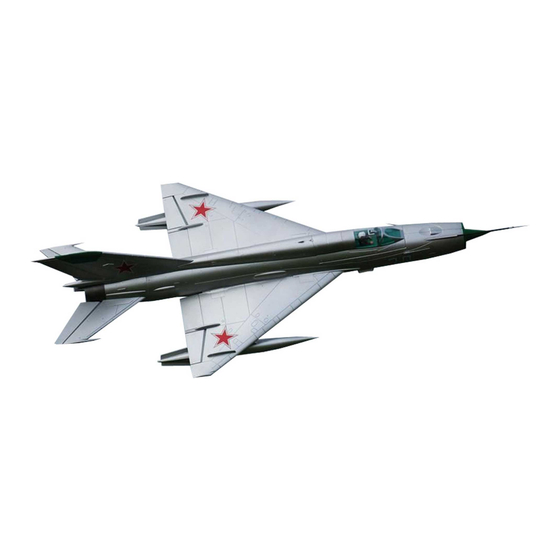
Freewing’s longest model aircraft. Its removable wings, horizontal stabilizer, and vertical stabilizer make transport very easy. Even the nose cone and pitot tube are removable! Freewing has recreated many scale details of the MiG-21 “MF” variant, and the aircraft is powered by an 80mm 12-blade EDF and an all-new 3530-1800KV out- runner motor and 100A ESC. - Page 3 Standard Version Wingloading:123g/dm Motor:3530-1800KV outrunner motor Fan:80mm 12-Blade fans ESC:100A UBEC 5A Servos:9g Digital MG (8pcs) (W/O battery) Weight:2180g Thrust:3000g 比例 1.000 Upgrade Version Wingloading:125g/dm Motor:3658-1820KV inrunner motor Fan:80mm 12-Blade fans 1730mm ESC:100A UBEC 5A (68.1") (8pcs) Servos:9g Digital MG Weight:2215g (W/O battery) The parameters stated here are derived from test results using our...
- Page 4 PNP Assembly Instructions Steel wire use instructions Our tests show that excessively long servo extension lines increase the risk of poor connections that can lead to servo brown outs or failure, causing accidents during flight. Instead, this kit contains a steel wire that can be used to pull the main wing/elevator and rudder servo wires through the airplane to the battery compartment, eliminating the need for extension wires.
- Page 5 PNP Assembly Instructions 3.Use 4 screws to secure the main wing. Screws (PM3x6 4pcs) 4.Use the steel wire to pull the left and right wing connection wires to the battery compartment. Main wing servos wire Landing gear wire 6.Use glue and screw to secure the intake plate. 5.Use plastic cover to close the main wing connection cable trough on the inner wall.
- Page 6 PNP Assembly Instructions Rudder Installation 1.Use the steel wire to pull the rudder servo cable through to the battery compartment. 2. Use 4 screws to secure the rudder. A. Vertical tail B. Tail fuselage C. Servo wire D. Screws (FA3x8 4pcs) Nose cone, pitot tube, wing fence and drop tank pylons Installation Nose cone Antenna...
- Page 7 Servo Installation Instructions Flap and Aileron Servo Installation A - 9g servo B - Main wing pushrod 1.Use a servo tester or radio to center the C - Aileron horn servo. D - Main wing servo trough 2.Use glue to install the servos and control horns to the main wing.
- Page 8 Landing Gear Nose Landing Gear Assembly Assemble and disassemble the nose landing gear according to the following photos. (PM2x4 1pc) Nose wheel Screw Retract controller Nose gear axle Nose gear main supporting rod Nose landing gear set U-shape slant supporting rod E-clip (Ø1.5mm) clip...
-
Page 9: Introduction
Landing Gear Installation Rear Landing Gear Assembly Assemble and disassemble the rear landing gear according to the following photo. Main gear axle Main landing gear set Main wheel (FA3x8 4pcs) Screws Screw (M3x3mm) Step Main landing gear mount Rear gear slant supporting rod (Ø3.5X9.2mm 1pc) E clip (Ø1.5mm 1pc) -
Page 10: Battery Installation
3-Axis Gyro Introduction and Use Use 4 screws to secure the gyro onto the board at the front of the The gyro was factory tested and set up at default sensitivity. You can battery compartment. Make sure the gyro decal is facing the nose cone fine tune it according to your preference and flight conditions. -
Page 11: Servo Introduction
Servo Introduction A servo or reversed servo is defined as follows: When the servo input signal changes from 1000ųs to 2000ųs, if the servo arm rotates clockwise, it's a positive servo. If it rotates counter clockwise, it's a reversed servo. If you choose to use another brand of servo, please refer to the following list to ensure it is the correct size . -
Page 12: Motor Parameters
Power System Assembly Motor spinner Screws 80mm ducted fan metal frame for outrunner motor 3553 - 1800KV motor 90mm 12-blade ducted fan Spinner (PM3×10mm 1pc) Screw ( 3×3mm 2pcs) Screws Refer to the following photo to install power system and ESC. PM3x25mm 2pcs) Screws Ducted fan cover... -
Page 13: Control Direction Test
Control direction test After the build is complete, power up the radio and connect a fully charged battery to the ESC. Use the radio to ensure correct control direction. Aileron Stick Left Stick Right Elevator Stick Back Stick Forward Rudder Stick Left Stick Right Optional Flaps... -
Page 14: Dual Rates
Dual Rates According to our test results, the following rates proved to be a good starting point. Low rates are good for initial flights or less experienced pilots. High Rates will be more sensitive to control inputs After initial flights, adjust the rates to suit your own style. Ailerons Flaps Elevator... - Page 15 前 言 中文版 历史简介 1953年开始设计的MIG-21,是60年代前苏联空军主力制空战斗机。此机是第二次世界大战后,生产数量最多的超音 速喷气式战斗机,总产量超过6000架(不包括中国引进改型的歼7系列战斗机),在全世界,约50个国家和地区使用过该 款战斗机。 模型概述 飞翼1/9比例MIG-21MF,机长1730mm,翼展800mm,这款模型的外形线条及轮廓,完全依据真实飞机按比例缩 小制作,细节的处理,使外形更加逼真。大量使用塑料零件,使我们可以快速、便捷安装主翼、平尾及垂尾。较长的空速 管和机鼻,可重复拆解,防止运输过程造成损坏。MIG-21MF模型,采用12叶80mm金属外框涵道风扇,3553-1720外 转无刷马达,100A ESC。全机采用了8个9g金属数字分别控制垂尾、方向舵、升降舵、副翼和襟翼,新型集线盒的使用, 不仅使设备舱更加整洁,而且能够有效减少内置连接线,降低飞行时接触不良导致事故的风险。更大型号的涡杆控制器和 全金属避震起落架,更加牢固、可靠。 新 的 80mm外 转 动 力 系 统 , 在 高 性 价 比 的 基 础 上 , 给 MIG-21MF模 型 带 来 强 悍 的 动 力 , 最 高 时 速 达 到 160kph/100mph。...
- Page 16 产 品 基 本 参 数 中文版 标 准 版 翼载荷:123g/dm 电机:3530-1800KV外转无刷电机 涵道风扇:80mm 12叶涵道 电调:100A无刷电调 UBEC 5A 舵机:9g数字金属舵机 (8pcs) 重量:2180g (不含电池) 推力:3000g 比例 1.000 升 级 版 翼载荷:125g/dm 电机:3658-1820KV内转无刷电机 涵道风扇:80mm 12叶涵道 电调:100A无刷电调 UBEC 5A 舵机:9g数字金属舵机 (8pcs) 1730mm 重量:2215g (不含电池) (68.1") 推力:3200g 其...
- Page 17 PNP 组装说明 中文版 牵 引 钢 丝 使 用 说 明 通过调查,过多的舵机延长线会加大连接处接触不良的风险,严重时,导致飞行过程,舵机断电而造成飞行事故。由于MIG-21内部线 槽空间大且平直,故此模型的机体内,未使用舵机延长线。如下图所示,包装盒内包含一根牵引钢丝,PNP配置下,我们可以利用这根 牵引钢丝,顺利的将主翼、平尾、垂尾舵机线布置到电池舱内。 组 装 前 准 备 1.打开座舱,松开固定电池托盘的二颗螺丝,取出电池托盘。 2.取下机腹进气栅。 (KA3x10mm 螺丝 4pcs) 电池托盘 进气栅 机 身 组 装 1.使用胶水粘合前、后段机体 注:包装盒内有赠送的EPO胶水,请使 用这支赠送的胶水进行粘合作业。涂 摸胶水应该均匀。胶水均匀涂摸完毕, 不要立即粘合,请等待90秒时间,再 进行粘合,效果最佳! 2.使用牵引钢丝,将平尾舵机线拉入电池舱内。 平尾舵机线 主 翼 组...
- Page 18 PNP 组装说明 中文版 3.用4颗螺丝固定主翼。 螺丝 (PM3x6 4pcs) 4.使用牵引钢丝,分二次将左、右二侧主翼连接线拉入电池舱内。 主翼舵机、起落架连接线 5.使用线槽塑料盖封闭进气道内壁上的主翼连接线线槽。 6.使用胶水和螺丝固定进气栅。 螺丝 (FA3x8mm) 平 尾 、 垂 尾 尾部 机身 螺丝 (KA2.6x8 4pcs) 平 尾 组 装 1.将平尾插入到机身尾部。 2.用2颗螺丝拧紧固定平尾。 3.重复以上步骤安装另一侧平尾。 MIG-21MF FISHBED Item No.:FJ210...
- Page 19 PNP 组装说明 中文版 垂 尾 组 装 使用牵引钢丝,将方向舵机线拉入电池舱内。 2.用4颗螺丝固定垂尾。 垂尾 尾部机身 舵机线 螺丝 (FA3x8 4pcs) 机鼻、空速管、 翼刀 及 副油箱 挂架组装 配件名称及规格参数 机 鼻 天线 空速管零件1 碳纤管 (Ø5x180mm) 空速管零件2 塑料件1(左、右) 塑料件2 翼刀 腹鳍 挂架 副油箱 注意:1.完成以上步骤后,根据集线盒上的内容通道标识,将所有舵机插入到集线盒内。 2. 最后用4颗螺丝固定电池托盘(所有舵机线处于电池托盘下方)。 MIG-21MF FISHBED Item No.:FJ210...
- Page 20 舵机安装说明 中文版 主 翼 舵 机 安 装 舵机 主翼舵机控制钢丝 1.通过舵机测试仪或者遥控器,把 舵面摇臂 舵机摇臂校正到居中位置; 舵机线槽 2.用胶水分别把舵机和舵面摇臂粘 到主翼; 3.将舵机线卡到舵机线槽内,待所 有主翼舵机安装完成,贴上贴纸; 4.钢丝一端穿入到舵机摇臂后,调 节钢丝长度,在保持舵面居中的 情况下,将夹头扣入舵面摇臂内; 5.重复以上4个步骤,安装另外一侧 主翼舵机。 平 尾 舵 机 安 装 舵机 舵面摇臂 1.通过舵机测试仪或者遥控器,把舵 舵机控制钢丝 机摇臂校正到居中位置; 2.如右图所示,使用胶水把舵机和舵 面摇臂粘到平尾; 3.钢丝一端穿入到舵机摇臂后,调 节钢丝长度,在保持舵面居中的 情况下,将夹头扣入舵面摇臂内; 4.重复以上3个步骤,安装另外一侧 平尾舵机。...
- Page 21 起 落 架 组 装 介 绍 中文版 前 起 落 架 组 装 请参考以下图示,组装、更换、维修前起落架 前机轮 螺丝 前起落架收放控制器 (PM2x4 1pcs) 前轮轮轴 前起落架主撑杆 U型斜撑杆 E型扣 前起落架组件 (Ø1.5mm) E型扣 梢钉 螺丝 (PA3x8 4pcs) (Ø2.0pcs) (Ø3.5x9.2mm) 梢钉 L型摇臂 前起落架固定座 (Ø3.5X9.2mm 2pcs) E型扣 前起落架舵机控制钢丝 机米螺丝...
- Page 22 起 落 架 组 装 介 绍 中文版 后 起 落 架 组 装 请参考以下图示,组装、更换、维修后起落架 轮轴 后起落架组件 螺丝 机轮 (FA3x8 4pcs) 步骤 机米螺丝 后起落架固定座 (M3x3mm) 后起落架斜撑杆 梢钉 (Ø3.5X9.2mm 1pcs) E型扣 (Ø1.5mm 1pcs) 后起落架主撑杆A 机米螺丝 (M4x3mm) 弹簧 螺丝 (PM3x4 1pcs) 后起落架主撑杆B 后起落架钢丝...
- Page 23 陀 螺 仪 使 用 说 明 中文版 用四颗螺丝将陀螺仪固定在电池舱最前端的固定板上。安装时, 出厂时,陀螺仪已经通过测试,并设置好默认感度值,您可以 确定陀螺仪贴纸上的LOGO朝机头方向! 根据实际情况,进行小幅度调整。 螺丝 3x8mm 4pcs MIG-21使用E51陀螺仪建议感度值,请参考此图。 陀螺仪 固定板 陀 螺 仪 连 接 示 意 图 1.请正确安放陀螺仪, 2.将平尾、方向及副翼舵机线分别接入陀螺仪输出端; 3.使用3根连接线,将陀螺仪输入端与接收机对应通道连接; 4.如果您的接收机通道数目允许,您可以再使用一根连接线连接陀螺仪与接收机,用来设置陀螺仪(开启/关闭)开关。 5.陀螺仪详细使用方法,请参考《陀螺仪使用说明书》。 遥控器 接收 机 副翼舵机 升降舵机 方向舵机 电 池 安 装 说 明 电池安装在最前方,用魔术带绑紧...
- Page 24 舵 机 使 用 介 绍 中文版 我们的舵机正、反向标准是: 当舵机输入信号从 到 时, 如果舵机摇臂, 顺时针旋转---正向舵机 逆时针旋转---反向舵机 如果您需要选购其它品牌的舵机进行安装, 请参考下面的表格选择正确的舵机 舵机使用位置 序号 正、反向 舵机线长 前轮转向 正向 100mm 左副翼 正向 950mm 右副翼 正向 950mm 左襟翼 正向 800mm 右襟翼 反向 800mm 左平尾 正向 1050mm 右平尾 反向 1050mm 垂尾...
- Page 25 动 力 系 统 的 安 装 中文版 标准版 电机整流罩 螺丝 (PM3x6mm) 80金属外转涵道框 3553-1800 KV外转无刷马达 80mm 12叶风扇叶 整流罩 螺丝 (PM3x10mm) 机米螺丝 (M3x3mm) 按以下图示安装动力组及电调: 螺丝 涵道底盖 PM3x25mm 2pcs) 电调固定木片1 螺丝 (FA3x8mm 2pcs) 电调 腹鳍 电调固定木片2 腹鳍固定座 注意:当电调与电池连接后,禁止用手 螺丝 螺丝 (KA2.6x8mm 1pcs) 触摸电调和涵道,防止意外伤害!测试涵道...
- Page 26 舵 面 测 试 中文版 当您按前面的步骤组装好飞机后,在飞行前,我们需要用一块充饱电的电池,连接到电调。用遥控 器测试每个舵面的工作情况,检查是否正常! 副 翼 副翼摇杆 副翼摇杆 向左运动 向右运动 升降舵 升降摇杆 升降摇杆 向下运动 向上运动 方向舵 方向摇杆 方向摇杆 向左运动 向右运动 襟 翼 襟翼放下 MIG-21MF FISHBED Item No.:FJ210...
- Page 27 大 、 小 舵 参 数 中文版 根据我们的测试经验,我们认为,按以下参数来设置副翼和升降舵的大、小舵,将有助于 飞行。在小舵角的情况下,飞机的可操控性能会好一些,适合初次飞行或者不太熟练的玩 家飞行。而大舵角的设置,可以提高动作灵敏度,使用经验丰富的玩家。您可以根据自身 的情况,来选择其中一种舵量进行飞行! 副 翼 襟 翼 升 降 舵 方 向 舵 副翼 升降舵 方向舵 襟翼 H1/H2 16mm/16mm H1/H2 30mm/30mm H1/H2 20mm/20mm 小舵量 H1 30mm 舵量比率:80% 舵量比率:100% 舵量比率:85% H1/H2 20mm/20mm H1/H2 30mm/30mm H1/H2 24mm/24mm 大舵量...
- Page 28 Dongguan Freewing Electronic Technology Ltd HK Freewing Model International Limited Add.: FeiYi Building,face to Labor Bureau, Fumin Middle Road, Dalang Town, Dongguan City,Guangdong Province, China Web: http://www.sz-freewing.com Email:freewing@sz-freewing.com Tel: 86-769-82669669 Fax:86-769-82033233 东莞市飞翼电子科技有限公司 香 港 飞 翼 模 型 国 际 有 限 公 司...
Need help?
Do you have a question about the MIG-21 FISHBED and is the answer not in the manual?
Questions and answers