Table of Contents
Advertisement
Advertisement
Table of Contents

Related Manuals for Make Noise TEMPI


Summary of Contents for Make Noise TEMPI
- Page 1 v2.7...
-
Page 2: Table Of Contents
TEMPI FCC ------------------------------------------------------------------3 Limited Warranty -------------------------------------------------4 Installation ----------------------------------------------------------5 Overview ---------------------------------------------------------------6 Panel Controls ---------------------------------------------------7 Factory Settings ----------------------------------------------------8 Quick Reference ----------------------------------------------------9 Leading Tempo ------------------------------------------------------11 Human Programming --------------------------------------------12 Machine Programming --------------------------------------------13 Phase Programming ------------------------------------------15 Mute Page ----------------------------------------------------------17 Mod Page ---------------------------------------------------------18 Program Edit ------------------------------------------------------19... -
Page 3: Fcc
This equipment generates, uses, and can radiate radio frequency energy and, if not installed and used in accordance with the instruction manual, may cause harmful interference to radio communications. makenoisemusic.com Make Noise Co., 414 Haywood Road, Asheville, NC 28806... -
Page 4: Limited Warranty
Make Noise to be the fault of the user are not covered by this warranty, and normal service rates will apply. During the warranty period, any defective products will be repaired or replaced, at the option of Make Noise, on a return-to-Make Noise basis with the customer paying the transit cost to Make Noise. -
Page 5: Installation
Eurorack style bus board, minding the polarity so that the RED stripe on the cable is oriented to the NEGATIVE 12 Volt line on both the module and the bus board. On the Make Noise 6U or 3U Busboard, the NEGATIVE 12 Volt line is indicated by the white stripe. -
Page 6: Overview
TEMPI is deep, but all you really need to know: patch a clock to the Leading Tempo Input and tap any Channel Button at a clock rate of your choice. The Channel Button's LEDs ash to indicate the current clock rate, which changes in speed to match your taps. -
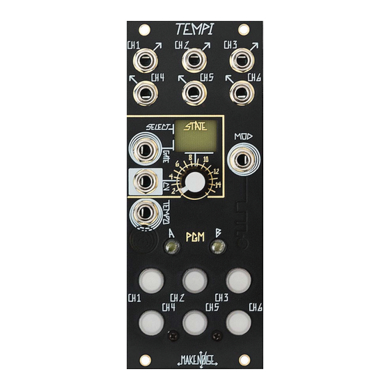
Page 7: Panel Controls
PAN EL ConTRoLS TEMPI Panel Controls 13. PGM_B Button/ LED 1. Channel 1 Output Channel Button-1 / LED 2. Channel 2 Output 15. Channel Button-2 / LED 3. Channel 3 Output 16. Channel Button-3 / LED 4. Channel 4 Output 17. -
Page 8: Factory Settings
When you rst power up a new TEMPI, Bank A will be lled with (16) States representing a selection of classic and new Clock Divider/Multiplier settings. All these settings are user-editable and can be overwritten at will. Here's a short description: STATE 1 All (6) CHannels are “÷1.”... -
Page 9: Quick Reference
QUICK REFERENCE: Human Programming Human Programming of Multiple and Divisions of Leading Tempo If enabled on Clock Edit Page, Tap Button1 to set Leading Tempo Machine Programming Variable Clock Phase Adjustment Multiplier / Divisor [Press] PGM_A + PGM_B = On [Hold] PGM_A + [Press] Channel Button1-6 n times [Hold] CHannel BUTTON1-6: for Variable Clock Divisor Coarse adjustment (1÷n) - Page 10 ( CONT'D ) Bank Edit [Press 2x] PGM_A = Flashing [Press] Button-1 to Select Bank [Press] Button-2 to Store All Banks and current Leading Tempo [Press] Button-3 to Follow the Select and Tempo Busses [Press] Button-4 to Copy selected Bank [Press] Button-5 to Paste over selected Bank [Press] Button-6 to Mutate over selected Bank [Press] PGM_A to Exit Bank Edit...
-
Page 11: Leading Tempo
Also, for DAW Sync, try Run/Stop All (James Cigler mode) described on Page 20. It is possible to tap the Leading Tempo by patching a Gate Output, for example, from the Pressure Points, to TEMPI’s Tempo Input and tapping the desired Tempo on the Pressure Points. -
Page 12: Human Programming
Programming Variable Clocks: Human Programming Human Clock Programming combines Multiplier/Divisor and Phase Settings For HUMAN Programming: into one simple, tactile process. For Human Programming, patch the Leading Tempo (i.e. MULT of the clock patched to Tempo Input or any Channel set to 1:1 using Machine Multiplier or Divisor) so that the timing is audible. -
Page 13: Machine Programming
Variable Clock Output. It is possible to tap Channel Buttons1-6 simultaneously in order to Program several Channels at once. The TEMPI counts the taps and sets this number as the Divisor value for each Channel. If (32) taps are exceeded, the count stays at maximum number of (32) and the counting of subsequent taps is stopped. - Page 14 Machine Programming Multiplier/Divisor: (cont’d) For Variable Clock Multiplier / Divisor Fine adjustment: For Variable Clock Fine decrement (i.e. to make [PRESS] PGM_A for slower), hold the associated Channel Variable Clock Button1-6 and press PGM_A. The State LED Fine decrement ashes Red to indicate a Variable Clock Fine decrement has been made.
-
Page 15: Phase Programming
Machine Programming : Phase To begin Phase Programming, The other way to Machine Program is by making Phase [press] PGM_A and PGM_B adjustments. To enter the Phase Programming Page, press PGM_A and PGM_B at the same time. While in the Phase Page, both PGM_LEDs are on. - Page 16 Machine Programming: Phase (cont’d) While still on the Phase Programming Page: For Fine Phase adjustment: [HOLD] Buttons(s)1-6 For Fine Phase decrement, hold the [press] PGM_A to associated Channel Button(s)1-6 and Fine Phase decrement press PGM_A. The State LED (i.e. lead ahead of Leading TEMPO) ashes red to indicate a Fine Phase decrement has been made.
-
Page 17: Mute Page
Mute To Mute a Channel output, press PGM_A to toggle access the Mute Page. In order to exit the Mute Page, press PGM_A again. The associated PGM_A LED lights to indicate that the Mute page is active. While active, State changes are ignored. To Mute a Channel, now press its associated Channel Button to toggle its Variable Clock Output on/o . -
Page 18: Mod Page
Programming of the Mod Settings in SETTINGS the Program Edit page. The Mod Input a ects the TEMPI according [Press] Button4 for Shift: to the Shift Behavior (causes timing information to move between Mod-enabled Channels at each new Gate) and Run/Stop (causes Blue some or all Channels to Run, Stop, and/or Reset). -
Page 19: Program Edit
Mod Enabled Channel. These changes always occur at the Rising Edge of the signal patched to the Mod Input so that when a Gate High is read, the Mod LED ashes Magenta and the Shift occurs immediately, allowing for an TEMPI Channel patched to the Mod Input to control the Variable Clocks Shifts. - Page 20 Beginning or End. If synchronizing the TEMPI to DAW project, with the sync clock running, include 2 bars of silence at the beginning of composition so that TEMPI is locked into sync when it rst receives the Run signal at the Mod Input.
- Page 21 Progam Edit: Run/Stop (cont’d) While on the Program Edit Page, Button-6 sets the behavior of the Mod Input jack for Shift and Reset behaviors to be Jumbled or Unjumbled. Unjumbled Jumbled Button-6 = O Button-6 = Red Jumbled Button-6 = Red Any Phase O set changes created by Run/Stop messages will be preserved when navigating away from and back to a given State.
-
Page 22: State Edit
0V to 5V. To Reset to State 1, patch a Gate to the State Select CV Input and set the Combo Pot/attenuator so at Gate High, TEMPI goes to the last State you would like to use (e.g. State 8). Next, patch a Clock or Gate to the State Select Gate Input and step through States 1 through 8. - Page 23 State Edit: Copy, Paste, and Mutate State In order to audition and select a State to Copy, rst use the State Select Panel Control to accurately choose the desired State. Note: you may have to remove any modulation source patched to the Select CV Input. When you nd the desired State, hold both PGM_A + PGM_B and press Button-4 to Copy.
-
Page 24: Bank Edit
Bank Edit Settings In order to enter the Bank Edit Programming page, double press PGM_A. The PGM_A LED ashes in order to indicate Bank Edit. To exit the Bank Edit Programming page, double press PGM_A again. Bank Edit [Double Press] PGM_A: [Press] Button-1 to Select Bank [Press] Button-2 to Store All Banks and current Leading Tempo [Press] Button-3 to Follow Select &... - Page 25 Bank Edit Settings (CONT’d) COPY, PASTE, and MUTATE BANKS: While on the Bank Edit Page, Press Button-1 to select the Bank to Copy. When you nd the desired Bank, press Button-4 to Copy. In order to Paste, press Button1 to select the Bank into which you would like to Paste. Keep in mind: you will be overwriting what is Stored in the selected Bank! Lastly, press Button-5 to complete the Paste operation.
-
Page 26: Lead / Follow
Free / Follow While on the Bank Edit Page, press Button-3 to set the TEMPI to Follow the Tempo and Select Busses. The TEMPO LED changes to GREEN in order to indicate Follow. Press BUTTON-3 again to set TEMPI to be Free of the Tempo and Select Busses, indicated by the Blue Tempo LED. -
Page 27: Select And Tempo Busses
The Select Bus and Tempo Bus utilize the often-inactive CV and GATE Busses in the Eurorack system in order to allow remote (i.e. patch-less) control of State Selection and Tempo for TEMPI and other modules designed with this standard in mind. Any number of TEMPI on the same Bus Board can be controlled simultaneously by these signals, simplifying the process of macro-control over complex changes in a patch. -
Page 28: Tips & Tricks
•To Reset to State 1, patch a Gate to the State Select CV Input and set the Combo Pot/attenuator so at Gate High, TEMPI goes to the last State you would like to use (e.g. State 8). Next, patch a Clock or Gate to the State Select Gate Input and step through States 1 through 8. -
Page 29: Patch Ideas
Using TEMPI to drive Rene: Patch from two Channels of TEMPI’s output to Rene’s X-CLK and Y-CLK Inputs. Human Program one of the clocks to be a division of the other. Observe the Rene’s Cartesian behavior. Optionally, try patching the remaining clocks from the TEMPI to the Rene’s X-Mod and Y-Mod inputs and experiment with the various Gate Logic settings on the X-Fun and Y-Fun pages (see Rene Manual, Appendix D ). - Page 30 Gates driving the Leading Tempo change from half-time to 1:1 and back. (Recall: it takes two clock pulses in order for TEMPI to program a new Leading Tempo). To best hear this e ect, use one or more of the TEMPI’s Outputs to Strike a Low Pass Gate like the Optomix or LxD.
Need help?
Do you have a question about the TEMPI and is the answer not in the manual?
Questions and answers