
Related Manuals for Make Noise MMG


Summary of Contents for Make Noise MMG
- Page 2 Malfunction resulting from wrong power supply voltages, backwards power cable connection, abuse of the product or any other causes determined by Make Noise to be the fault of the user are not covered by this warranty, and normal service rates will apply.
-
Page 3: Installation
Installation: The Make Noise MMG is an electronic signal generator requiring 50mA of +/-12V of regulated power and properly formatted distribution receptacle to operate. It is designed to be used within the euro format modular synthesizer system. Go to http://www.doepfer.de/a100_man/a100t_e.htm for the details of this format. - Page 4 Overview: The MMG is a Vactrol based Voltage Controlled Filter and Low Pass Gate using our QMMG core. The MMG bridges the Far East and West Coast synthesis styles by allowing for highly resonant acidic squelch and organic, percussive animations to be programmed simultaneously with a single module.
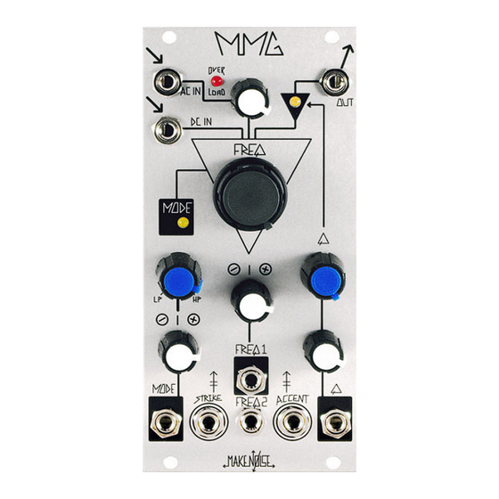
- Page 5 MMG Panel Controls INPUT 1A DC IN: Direct Coupled Input. Expects 10Vpp. 2A AC IN: AC coupled Input. Expects 10Vpp. 3A Over Load Indicator: Lights when inputs exceed ideal levels for circuit. 4A AC IN Drive: Sets input level for AC IN.
- Page 6 5D ACCENT Input: Briefly pushes entire filter circuit to 110% OUTPUT 1E Signal OUT: AC and DC Input signals, as processed by the MMG circuits, is output here. FREQuency 1C STRIKE Input: Briefly opens the filter circuit to 100%. Expects 8 to 10V Gate or clock.
- Page 7 However, the MMG has a steeper filter slope of 12db/ Octave, so it will not sound the same as the typical Low Pass Gate (such as the Make Noise Optomix).
- Page 8 The INPUT Stage: There are two inputs which allows for mixing two signals at the input of the MMG. One input is marked AC IN and the other is marked DC IN. These names reflect how the signal is coupled into the circuit.
- Page 9 The OUTPUT Stage There is one output on the MMG. There is one thing about that single output stage that is not typical though, and that is the inclusion of an Automatic Gain Control circuit. This AGC circuit is not found on the original QMMG.
-
Page 10: Tips And Tricks
TIPs and TRICKS: -To achieve classic Low Pass Gate sounds, use a complex audio signal source such as a Frequency Modulated SINE wave and apply Gate or Clock signal to STRIKE Input. Set FREQ to Full CCW (0%). -At lowest cut-off frequencies the High-Pass filter setting will seem to pass the signal with no change. Conversely, at highest cut-off frequencies the Low Pass filter setting will seem to pass the signal with little change. - Page 11 Calibrating the MMG Requires small flat head screw driver or trimmer tool, Square Wave reference signal, monitors. If available, an oscilloscope and DVM are useful. All trimmers are accessed from the left and right sides of the module. This will require the module to be lifted out of the system for calibration.
- Page 12 (due to clipping in the resonance circuit). Adjust trimmer 3 to taste. At Make Noise we set so first 50% of Q rotation is clean resonance, and second half of Q rotation is dirtier resonance. Using scope observe clipping and amplitude.
Need help?
Do you have a question about the MMG and is the answer not in the manual?
Questions and answers