
Related Manuals for Make Noise DPO


Summary of Contents for Make Noise DPO
- Page 2 Malfunction resulting from wrong power supply voltages, backwards power cable connection, abuse of the product or any other causes determined by Make Noise to be the fault of the user are not covered by this warranty, and normal service rates will apply.
-
Page 3: Installation
Installation: The Make Noise DPO is an electronic signal generator requiring 70mA of +/-12V of regulated power and properly formatted distribution receptacle to operate. It is designed to be used within the euro format modular synthesizer system. Go to http://www.doepfer.de/a100_man/a100t_e.htm for the details of this format. - Page 4 Dynamic FM, Circular FM, Hard Sync and Additive Harmonic synthesis processes are all achieved with internal routing on the DPO. The idea being that the artist will utilize patch cables to expand upon these standard concepts or interrupt them completely by simply patching into the associated modulation destinations.
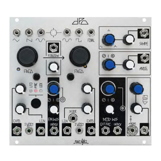
- Page 5 2A 3A 2B 3B 10A 11A 10B 11B VCO A 1A Triangle Waveform OUT: 10Vpp Sawtooth Waveform OUT: 9Vpp Sine Waveform OUT: 10Vpp Coarse Tune panel control: 9.5 octave range 12hz-6khz 1V/ Octave Scale Trimmer (see calibration procedure) Fine Tune panel control: 1.75 octave range Expo Attenuator: uni-polar attenuator for Exponential frequency control input Linear FM Attenuator: uni-polar attenuator for Linear FM input Expo INput: Exponential frequency control input.
- Page 6 VCO Interaction 1. Beat Frequency LED: visual indication of Phase difference between VCOs A & B. 2. FOLLOW CV INput: unipolar control input. Range 0V to 5V. 3. FOLLOW Attenuator: determines how well VCO A will FOLLOW VCO B. With nothing patched to FOLLOW CV IN works as standard panel control.
- Page 7 3D 4D 5D VCO B Timbre Controls and MOD Bus 1A. SHAPE Panel Control: unipolar control that determines the shape of the waveform feeding the FOLDing circuit. Morphs from Sine to Spike to Glitched Triangle. 2A. SHAPE CV Attenuator: unipolar attenuator for SHAPE CV IN. 3A.
- Page 8 Circular FM capabilities. These sounds will get out of hand quickly. The key to controlled FM within the DPO is attenuation since setting the Index to 100% really does push the circuit to its limits. VCO A core behavior With none of the LEDs lighted VCO A operates as a Standard Triangle Core oscillator.
- Page 9 CV (as on the Optomix CV ins), allowing for external control over how VCO A follows VCO B. Follow is useful in maintaining FM or SYNC Ratios while controlling the DPO with a sequencer or keyboard. The lag that occurs when FOLLOW is set to less than 100% will introduce moments of dissonance and noise due to the temporary tracking errors.
- Page 10 MOD BUS and Timbre Shaping Sections: Mod Bus The internal Mod Bus SOURCE is hardwired for VCO A SINE wave, with the power to use any external source by patching to the EXT. SouRCe Input. The internal MOD bus system makes use of the Normaliza- tion Switch found on the mini-jacks, so with nothing patched to the Shape, Angle and Fold CV inputs the associated attenuator sets the final amount of modulation applied to the destination.
- Page 11 The phase reversal and Amplitude Modulation that occurs around the 50% range of the SHAPE parameter value is useful on it’s own (before FOLDing occurs) for subtle and pleasing modulations via LFO. The SHAPE circuit is slow and smooth with a unique response quite unlike the typical balanced modulator or VCA.
- Page 12 SQUARE is the waveform of choice for performing eXternal LOCK patches between multiple DPOs where the chain of command is passed from one DPO down to the next. Like the SAW, the SQUARE shape is also very useful for performing Subtractive synthesis.
- Page 13 NOON. Set Mod Bus panel control to NOON. Patch Gate from sequencer or CV KB to STRIKE INput of DPO. Push button to select LFO behavior at VCO A. Set VCO A FREQ. to around 9 o' Clock and set Follow p to full clockwise (100%).
- Page 14 Requires small flat head screw driver or trimmer tool, tuned reference signal, oscilloscope. NOTE: if you plan to use the DPO with another VCO or Synth in your system (even another DPO), it is a good idea to use that VCO/ Synth for your reference signal, assuming it is calibrated to your satisfaction. The same is true of the quantizer or MIDI to CV interface.
- Page 15 DPO VCO A pitch matches that of the reference (DPO VCO B). 10. Send note C3 to the DPO and adjust the VCO A 1V/ Octave Trimmer (3A) on the DPO so the pitch matches that of the reference.
- Page 16 FM Bus and Fold circuits to operate correctly. See the last step of the VCO B FINAL OUT Calibration for more details. NOTE: Amplitude should not require adjustment in most cases. Expect some small amount of harmonics in the SINE shape. Trim to satisfaction and then go make noise!
- Page 17 Calibrating the VCO B FINAL OUT Trims for FINAL OUT are SHAPE Balance (3) which is accessed through the top side of the module and FOLD Gain (4) which is accessed through the right side of the module. Take care in lifting the module out of case for calibration.
Need help?
Do you have a question about the DPO and is the answer not in the manual?
Questions and answers