Table of Contents
Advertisement
Advertisement
Table of Contents

Related Manuals for Pentair FLECK 7000XTR


Summary of Contents for Pentair FLECK 7000XTR
- Page 1 FLECK 7000XTR SERVICE MANUAL www.pentairaqua.com...
-
Page 2: Table Of Contents
TABLE OF CONTENTS IMPORTANT PLEASE READ: • The information, specifications and illustrations in this JOB SPECIFICATION SHEET ..........3 manual are based on the latest information available at WATER SOFTENER CONTROL VALVE ........4 the time of printing. The manufacturer reserves the right VALVE INSTALLATION AND START-UP PROCEDURES ..4 to make changes at any time without notice. -
Page 3: Job Specification Sheet
JOB SPECIFICATION SHEET 14. CPO Aux Relay Volume:__________(Gallons or M 15. CPO Aux Relay: _ _ : _ _ : _ _ NOTE: Some options may not be available depending on valve model or other options chosen. 16. Flow Meter Size: 1.25-inch Turbine Circle and/or fill in the appropriate data for future reference. -
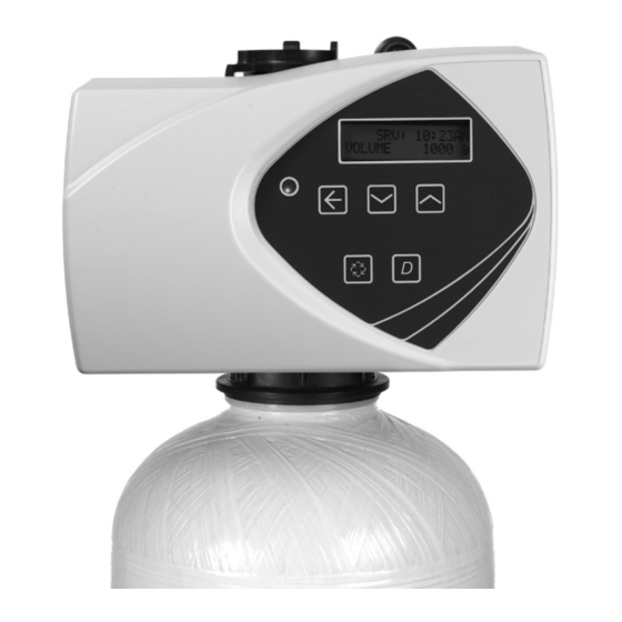
Page 4: Water Softener Control Valve
WATER SOFTENER CONTROL VALVE VALVE INSTALLATION AND START-UP PROCEDURES Water Pressure A minimum of 20 psi (1.3 bar) inlet water pressure is required Installation Instructions for regeneration valve to operate effectively. 1. Place the softener tank where you want to install the unit. Electrical Facilities NOTE: Be sure the tank is level and on a firm, clean base. -
Page 5: Timer Operation
TIMER OPERATION Regeneration • A time initiated control valve regenerates when the number of programmed days has been reached • A flow initiated control valve regenerates when the volume count is zero or is below reserve capacity System Type Regeneration Trigger Time Clock Delayed A) Day override parameter is reached and B) the time of day matches the regeneration... -
Page 6: Master Programming Mode Flow Chart
TIMER OPERATION CONTINUED MASTER PROGRAMMING MODE FLOW CHART Queued Regeneration (RGQ) From the display screen, while the unit is in service, hold down Before entering Master Programming, please CAUTION the Extra Cycle button until “RGQ” displays. The valve will contact your local professional water dealer. regenerate when the set regeneration time has been reached. - Page 7 MASTER PROGRAMMING MODE FLOW CHART CONTINUED FLECK • 7 7000XTR Service Manual...
-
Page 8: Master Programming Mode
MASTER PROGRAMMING MODE 4. Display Format This program step selects the display format. When the Master Programming Mode is entered, parameters • Press the Up or Down buttons to adjust this value. can be set to make the timer function as needed. •... - Page 9 MASTER PROGRAMMING MODE 13. Timed Auxiliary Relay Output Window (Start & End Time Setting) CONTINUED This option setting consists of two displays. The first display sets the turn-on time of the output, referenced to the start 9. Regeneration Day Override of the first regeneration cycle.
-
Page 10: User Programming Mode Flow Chart
USER PROGRAMMING MODE FLOW DIAGNOSTIC PROGRAMMING MODE FLOW CHART CHART NOTE: Depending on current option settings, some displays NOTE: Depending on current option settings, some displays cannot be viewed or set. cannot be viewed or set. Entering User Mode Entering Diagnostic Mode 1. -
Page 11: Diagnostic Programming Mode
DIAGNOSTIC PROGRAMMING MODE 9. Software Version This program step displays the timer’s software program NOTE: Depending on current option settings, some displays version number. cannot be viewed. • Press the Extra Cycle button to exit. Overview Diagnostic Mode NOTE: Diagnostic Programming Mode will stop if the system The current Diagnostic Programming Mode screen will display goes into a regeneration. -
Page 12: Power Head Assembly
POWER HEAD ASSEMBLY 61501-7000XT REV A Item No. Part No. Description Item No. Part No. Description 1 ....1 ..42349 ....Motor, 24V, 2 RPM, 7000 12 ....1 ..12473 ....Screw, Hex Wsh, 10-24 x 5/8 13 ....2 ..11805 ....Scerw, Rd Hd, 4-40 x 5/8 2 ....1 .. -
Page 13: Control Valve Assembly
CONTROL VALVE ASSEMBLY 61500-7000EXP REV C FLECK • 13 7000XTR Service Manual... - Page 14 CONTROL VALVE ASSEMBLY CONTINUED Item No. Qty. Part No. Description Item No. Part No. Description 10 ....1 ..61XXX ....DLFC Assemblies 1 ....1 ..61050 ....Valve Body Assy, 7000, 32 mm Dist DLFC Size/GPM 2 ....1 ..61542-10 ..Piston Assy, 7000, Softener, ..
-
Page 15: Bypass Assembly
BYPASS ASSEMBLY 41118 REV A 41147 REV A Important: To bypass the valve, turn bypass knob on both sides of the valve to bypass position. When returning to service, put the inlet into service before the outlet. Item No. Part No. Description 1 ....1 .. -
Page 16: 2310 Safety Brine Valve
2310 SAFETY BRINE VALVE 42112 REV A Item No. Part No. Description 1 ....1 ..60014 ....Safety Brine Valve Assy, 2310 2 ....1 ..60068-30 ..Float Assy, 2310, w/30-inch 3 ....1 ..60002-34 ..Air Check, #500 16 • FLECK 7000XTR Service Manual... -
Page 17: Troubleshooting
TROUBLESHOOTING Error Display Screen Examples: Timer If an error is detected, an error screen will alternate with the main display screen every few seconds, and the LED light will be red. During an error condition, the unit continues to monitor the flow meter and update the remaining capacity. - Page 18 TROUBLESHOOTING CONTINUED Control Valve The controller MUST be depressurized before WARNING: removing any quick connection clips for servicing. The connector should be pushed toward the control while removing clips. Problem Cause Correction Water conditioner fails to Electrical service to unit has been interrupted Assure permanent electrical service (check fuse, plug, regenerate.
-
Page 19: General Service Hints For Meter Control
GENERAL SERVICE HINTS FOR METER CONTROL Problem Cause Correction Softener delivers hard water Reserve capacity has been exceeded. Check salt dosage requirements and reset reserve capacity to provide additional reserve. Meter is not measuring flow. On Mechanical Meter: Check with meter checker kit. If volume is not registering, check the meter cap and impeller for debris, and ensure they can move freely. -
Page 20: Water Conditioner Flow Diagrams
WATER CONDITIONER FLOW DIAGRAMS Second Backwash Position In Service Position 40988 REV A 41121 REV A 40988 REV A 41121 REV A Backwash Position Rapid Rinse Position 40988 REV A 41121 REV A 40988 REV A 41121 REV A Brine Position Brine Tank Refill Position 40988 REV A 41121 REV A... -
Page 21: Removing The Gear Box Assembly
REMOVING THE GEAR BOX ASSEMBLY 42554 REV A 2. When all the way down, snap the circuit board into place 42554 REV A under the notches on the right. CONNECTING THE CIRCUIT BOARD 40988 REV A 1. Unplug the power source. 2. -
Page 22: Dimensional Drawings
DIMENSIONAL DRAWINGS 61500-7000XTR-LNE REV A METER FLOW DATA TR18753 Softener TR18688 Filter 41140-02 REV A 22 • FLECK 7000XTR Service Manual... -
Page 23: Injector Flow Data
INJECTOR FLOW DATA TR18755 REV B FLECK • 23 7000XTR Service Manual... - Page 24 All Pentair trademarks and logos are owned by Pentair, Inc. or its affiliates. All other registered and unregistered trademarks and logos are the property of their respective owners. Because we are continuously improving our products and services. Pentair reserves the right to change specifications without prior notice.
Need help?
Do you have a question about the FLECK 7000XTR and is the answer not in the manual?
Questions and answers