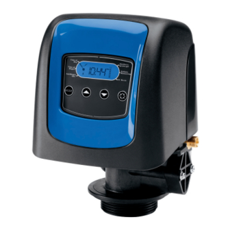
Pentair Fleck 5800 LXT Service Manual
Downflow/upflow control valve
Hide thumbs
Also See for Fleck 5800 LXT:
- Installer manual (96 pages) ,
- User manual (29 pages) ,
- Service manual (20 pages)
Table of Contents
Advertisement
Fleck 5800 LXT & SXT Downflow/Upflow
Service Manual
TABLE OF CONTENTS
1 - VALVE SPECIFICATIONS.................................................2
2 - GENERAL ADVICE ...........................................................3
3 - INSTALLATION INSTRUCTIONS .....................................3
4 - START-UP INSTRUCTIONS LXT .....................................4
5 - TIMER FEATURES LXT ....................................................4
6 - TIMER OPERATION LXT ..................................................5
7 - START-UP INSTRUCTIONS SXT .....................................6
8 - TIMER OPERATION SXT .................................................7
9 - MASTER PROGRAMMING MODE LXT ...........................8
10 - DIAGNOSTIC PROGRAMMING MODE LXT ..................10
11 - MASTER PROGRAMMING MODE CHART SXT ............11
12 - MASTER PROGRAMMING MODE SXT ........................12
13 - USER PROGRAMMING MODE SXT ..............................16
14 - DIAGNOSTIC PROGRAMMING MODE SXT .................17
15 - TROUBLESHOOTING LXT .............................................18
16 - TROUBLESHOOTING SXT ............................................19
17 - POWERHEAD ASSEMBLY LXT .....................................20
18 - POWERHEAD ASSEMBLY SXT .....................................21
UPFLOW .........................................................................22
20 - METER & ACCESSORIES..............................................23
21 - WATER CONDITIONER FLOW DIAGRAMS ..................21
The chart below is for dealer use only. These configurations
are the only available
Available configurations
Electronic Flow Mixing Regeneration
SXT
DF
yes
Time clock
SXT
DF
yes
SXT
DF
yes
SXT
UF
yes
Time clock
SXT
UF
yes
Filter
no
Time clock
LXT
DF
yes
Time clock
LXT
DF
yes
LXT
UF
yes
Time clock
LXT
UF
yes
LXT
Filter
no
Time clock
Injector DLFC BLFC
Start
1
1,5
0,25
ECO
1
1,5
0,25
ECO
0
1,2
0,25
00
1,2
0,25
ECO
00
1,2
0,25
NA
7
NA
1
1,5
0,25
ECO
1
1,5
0,25
0
1,2
0,25
ECO
0
1,2
0,25
NA
7
NA
43359 Rev A
MR12
Advertisement
Table of Contents
Troubleshooting

Related Manuals for Pentair Fleck 5800 LXT


Summary of Contents for Pentair Fleck 5800 LXT
-
Page 1: Table Of Contents
Fleck 5800 LXT & SXT Downflow/Upflow Service Manual TABLE OF CONTENTS The chart below is for dealer use only. These configurations 1 - VALVE SPECIFICATIONS..........2 are the only available 2 - GENERAL ADVICE ............3 3 - INSTALLATION INSTRUCTIONS ........3 Available configurations 4 - START-UP INSTRUCTIONS LXT ........4... -
Page 2: Valve Specifications
Brine line flow control (BLFC) without VOLTAGE 24V/50Hz Valves complying european regulations : Nr. 2004/108/CE, « Electromagnetic compability » Nr. 2006/95/CE, « Low voltage » Nr. D.M. 174/04, Italian regulation NOTES 2 • MR12 Fleck 5800 LXT & SXT Downflow/Upflow... -
Page 3: General Advice
15. Put the valve in brine refill position and let it get back to service position automatically. 16. Now you can add salt to the brine tank, the valve will operate automatically. Fleck 5800 LXT & SXT Downflow/Upflow MR12 • 3... -
Page 4: Start-Up Instructions Lxt
1. Press the Extra Cycle button. The service icon will flash to indicate that a regeneration is queued. 2. To cancel a queued regeneration, press the Extra Cycle button. Regenerating Immediately Press and hold the Extra Cycle button for five seconds. 4 • MR12 Fleck 5800 LXT & SXT Downflow/Upflow... -
Page 5: Timer Operation Lxt
Extra Cycle button. To clear a queued regeneration, press the Extra Cycle button again to cancel. If regeneration occurs for any reason prior to the delayed regeneration time, the manual regeneration request will be cleared. Fleck 5800 LXT & SXT Downflow/Upflow MR12 • 5... -
Page 6: Start-Up Instructions Sxt
• The Flow Indicator flashes when outlet flow is detected. • The Service Icon flashes if a regeneration cycle has been queued. • A Regeneration can be triggered immediately by pressing the Extra Cycle button for five seconds. 6 • MR12 Fleck 5800 LXT & SXT Downflow/Upflow... -
Page 7: Timer Operation Sxt
2. The timer advances to Regeneration Cycle Step #1 (rapid rinse), and begins programmed time count down. 3. Press the Extra Cycle button once to advance valve to Fleck 5800 LXT & SXT Downflow/Upflow MR12 • 7... -
Page 8: Master Programming Mode Lxt
Program icon disappears your changes will not be saved. NOTE: This unit has a day of the week reserve. It calculates a reserve for each day of the week based on the past 4 weeks. 8 • MR12 Fleck 5800 LXT & SXT Downflow/Upflow... - Page 9 Program icon disappears your changes will not be saved. NOTE: This unit has a day of the week reserve. It calculates a reserve for each day of the week based on the past 4 weeks. Fleck 5800 LXT & SXT Downflow/Upflow MR12 • 9...
-
Page 10: Diagnostic Programming Mode Lxt
Displays the average water usage for day 5, in cubic meters. Displays the average water usage for day 6, in cubic meters. Displays the average water usage for day 7, in cubic meters. 10 • MR12 Fleck 5800 LXT & SXT Downflow/Upflow... -
Page 11: Master Programming Mode Chart Sxt
NOTE: Some items may not be shown depending on timer configuration. The timer will discard any changes and exit Master Programming Mode if any button is not pressed for 5 minutes. Fleck 5800 LXT & SXT Downflow/Upflow MR12 • 11... -
Page 12: Sxt
Time of Day. This option setting is identified by "DF" in the upper left hand corner of the screen. Meter (Flow) Delayed There are two possible settings. Meter (Flow) Immediate Time Clock Day of Week 12 • MR12 Fleck 5800 LXT & SXT Downflow/Upflow... - Page 13 "OFF" disables this function. This option setting is identified by "DO" in the upper left hand corner of the screen. Use the Up Safety Factor and Down buttons to adjust the value as needed. Fixed Reserve Capacity Fleck 5800 LXT & SXT Downflow/Upflow MR12 • 13...
- Page 14 Press the Extra Cycle button to accept the current setting and move to the next parameter. Program the last cycle step as LC which forces the valve back to the service position. Figure 26 14 • MR12 Fleck 5800 LXT & SXT Downflow/Upflow...
- Page 15 Use the Up and Down buttons to enter the meter constant in pulses per unit volume. Figure 28 17. End of Master Programming Mode Press the Extra Cycle button to save all settings and exit Master Programming Mode. Fleck 5800 LXT & SXT Downflow/Upflow MR12 • 15...
-
Page 16: User Programming Mode Sxt
5. Press the Extra Cycle button. Use this display to adjust the Fixed Reserve Capacity. This option setting is identified by "RC" or "SF" in the upper left-hand corner of the screen. 16 • MR12 Fleck 5800 LXT & SXT Downflow/Upflow... -
Page 17: Diagnostic Programming Mode Sxt
4. Press the Up button. Use this display to view the Hours in Service since the last regeneration cycle. This option setting is identified by "HR" in the upper left hand corner of the screen. Fleck 5800 LXT & SXT Downflow/Upflow MR12 • 17... -
Page 18: Troubleshooting Lxt
---4 Fail Safe Error Valve has failed to find position in Unplug the unit and plug it back in. If error continues, call technical one minute. support. 18 • MR12 Fleck 5800 LXT & SXT Downflow/Upflow... -
Page 19: Troubleshooting Sxt
If error continues, call technical support. ---4 Fail Safe Error Valve has failed to find position in Unplug the unit and plug it back in. If error continues, call technical one minute. support. Fleck 5800 LXT & SXT Downflow/Upflow MR12 • 19... -
Page 20: Powerhead Assembly Lxt
1 ....1 ..61832-00 ....Cover Assembly, Black/Blue 2 ....1 ..61836....Panel Gear Assembly, Downflow/ Upflow 3 ....1 ..* ......E Timer 4 ....1 ..61835....Motor Assembly *Call your distributor for part number. 20 • MR12 Fleck 5800 LXT & SXT Downflow/Upflow... -
Page 21: Powerhead Assembly Sxt
Item No. Part No. Description 1 ....1 ..61832-00 ....Cover Assembly, Black/Blue 2 ....1 ..61836....Panel Gear Assembly, Downflow/ Upflow 3 ....1 ..61834....Timer Assembly, SXT 4 ....1 ..61835....Motor Assembly Fleck 5800 LXT & SXT Downflow/Upflow MR12 • 21... -
Page 22: 5800 Control Valve Assembly Downflow/Upflow
NOTE: In upflow units, the Injector Plug and Injector Assy are put in the ..60705-06 ....DLFC, Plastic, 0.60 gpm reverse holes. In filter units, both injector holes are plugged with 18276-01. 22 • MR12 Fleck 5800 LXT & SXT Downflow/Upflow... -
Page 23: Meter & Accessories
5 ....1 ..18706-12 ....Yoke 3/4" BSP male plastic 5 ....1 ..18706-10 ....Yoke 1" BSP male plastic 6 ....1 ..13398-10 ....Yoke 1" BSP female brass 7 ....1 ..24689....Yoke 3/4" BSP male brass Fleck 5800 LXT & SXT Downflow/Upflow MR12 • 23... -
Page 24: Water Conditioner Flow Diagrams
21 - WATER CONDITIONER FLOW DIAGRAMS Downflow 1. Service Position 4. Rapid Rinse Position 5. Brine Tank Refill Position 2. Backwash Position 3. Brine/Slow Rinse Position 24 • MR12 Fleck 5800 LXT & SXT Downflow/Upflow... - Page 25 21 - WATER CONDITIONER FLOW DIAGRAMS continued Upflow 1. Service Position 4. Rapid Rinse Position 2. Backwash Position 5. Brine Tank Refill Position 3. Brine/Slow Rinse Position Fleck 5800 LXT & SXT Downflow/Upflow MR12 • 25...
- Page 26 43359 Rev A MR12 26 • MR12 Fleck 5800 LXT & SXT Downflow/Upflow...
Need help?
Do you have a question about the Fleck 5800 LXT and is the answer not in the manual?
Questions and answers
Sveiki. Pentair 5800 lxt. Kai įsijungia praplovimas tai veikia kol pats rankiniu būdu neis jungi. Kokios priežastys? Vožtuvas apynaujis
The Pentair Fleck 5800 LXT may continue backwashing until manually turned off due to the following reasons:
1. Incorrect Backwash Time Setting – If the backwash time is set too long, the unit will continue the process until manually stopped.
2. Faulty Control Valve or Programming Issue – A malfunction in the control valve or an error in programming may prevent the system from advancing to the next cycle.
3. Sensor or Timer Malfunction – If the system's timer or sensors fail, it may not detect when to stop backwashing.
4. Power Interruption or System Reset – A power failure or system reset could cause the unit to get stuck in the backwashing cycle.
5. Mechanical Blockage or Valve Sticking – A physical blockage or mechanical failure in the valve could prevent the cycle from completing normally.
Adjusting the backwash time or checking for mechanical or electrical issues may help resolve the problem.
This answer is automatically generated
@Mr. Anderson
Kaip išvalyti uzsikimsusi vožtuvą pentair 5800 lxt
To clean a clogged valve on a Pentair Fleck 5800 LXT, follow these steps:
1. Disassemble the Valve:
- Remove the gearing system as described in the power head disassembly/replacement section.
- Unscrew and remove the piston and top plate.
2. Inspect and Clean Components:
- Remove the brine valve.
- Check for debris or blockages in the piston, seals, spacers, and brine valve.
- Clean the brine valve if necessary.
3. Replace Parts if Needed:
- If cleaning is insufficient, replace the piston and the seals & spacers cartridge.
- Replace or clean the brine valve.
4. Lubricate Seals:
- Apply only P-80® Emulsion lubricant (water-based) to all seals.
- Do not use petroleum-based lubricants, oils, or silicone grease.
5. Reassemble the Valve:
- Reverse the disassembly steps to rebuild the unit.
Following this procedure ensures proper cleaning and maintenance of the valve.
This answer is automatically generated