Table of Contents
Advertisement
Quick Links
Advertisement
Table of Contents

Related Manuals for Pentair FLECK 3900 NXT


Summary of Contents for Pentair FLECK 3900 NXT
- Page 1 INSTALLER MANUAL FLECK 3900 NXT/NXT2 INDUSTRIAL www.pentairaquaeurope.com...
-
Page 2: Table Of Contents
Installer manual Fleck 3900 NXT/NXT2 - Table of Contents Table of Contents Generalities ..................Scope of the documentation ............... Release management ................. Manufacturer identifier, product ..............Intended use ....................Abbreviations used ..................Norms......................1.6.1 Applicable norms ....................1.6.2 Available certificates................... - Page 3 Installer manual Fleck 3900 NXT/NXT2 - Table of Contents Sizing a softener (single unit) ..............33 4.2.1 Parameters to be considered ................4.2.2 Determining the required volume of resin ............4.2.3 Resin exchange capacity and capacity of the unit ..........
- Page 4 Installer manual Fleck 3900 NXT/NXT2 - Table of Contents 6.1.3 Setting the time of the day .................. 6.1.4 Basic programming mode .................. 6.1.5 Master programming mode................6.1.6 Diagnostic......................6.1.7 Resetting the controller ..................NXT2 Controller................... 88 6.2.1 Display ......................... 6.2.2 Commands ......................
- Page 5 Installer manual Fleck 3900 NXT/NXT2 - Table of Contents 9.3.3 Maintenance instructions ................... 139 Cleaning and maintenance................139 9.4.1 First steps......................139 9.4.2 Power head and/or motor replacement ............. 140 9.4.3 Lower power head motor replacement .............. 144 9.4.4 NXT to NXT2 controller upgrade................. 146 9.4.5...
- Page 6 Installer manual Fleck 3900 NXT/NXT2 - Table of Contents 11.12 Meter cables & meter kits list ..............181 11.13 CE compliance parts list ................182 11.14 Other components list................. 182 Disposal................... 183 6 / 184 Ref. MKT-IM-015 / D - 28.08.2020...
-
Page 7: Generalities
Installer manual Fleck 3900 NXT/NXT2 - Generalities Generalities Scope of the documentation The documentation provides the necessary information for appropriate use of the product. It informs the user to ensure efficient execution of the installation, operation or maintenance procedures. The content of this document is based on the information available at the time of publication. The original version of the document was written in English. -
Page 8: Intended Use
Installer manual Fleck 3900 NXT/NXT2 - Generalities Intended use The device is intended for industry environment use only and it is purpose-built for water treatment. Abbreviations used Assy Assembly BLFC Brine Line Flow Controller Brine Valve Cold Water Down Flow... -
Page 9: Available Certificates
Page 159]. If the problem persists contact your supplier. Copyright and Trademarks All indicated Pentair trademarks and logos are property of Pentair. Third party registered and unregistered trademarks and logos are the property of their respective owners. © 2020 Pentair. All rights reserved. -
Page 10: Limitation Of Liability
Pentair Quality System EMEA products benefit, under specific conditions, from a manufacturer warranty that may be invoked by Pentair’s direct customers. Users should contact the vendor of this product for applicable conditions and in case of a potential warranty claim. -
Page 11: Scan & Service Application
Installer manual Fleck 3900 NXT/NXT2 - Generalities 1.10 Scan & Service application Scan & Service mobile application is the ideal support for the maintenance person in his daily business. A simple scan of an identification (ID) label (1) present on the valve with a smartphone gives an instantaneously access to all updated information related to the product, such as: •... -
Page 12: Safety
Installer manual Fleck 3900 NXT/NXT2 - Safety Safety Safety pictograms definition DANGER This combination of symbol and keyword indicates an imminently hazardous situation that will result in serious or fatal injury if not avoided. WARNING This combination of symbol and keyword indicates a potentially hazardous situation that can result in serious or fatal injury if not avoided. -
Page 13: Serial Label Location
Installer manual Fleck 3900 NXT/NXT2 - Safety Serial label location Model Part number Electrical rating Serial number Production date Production order Mandatory Ensure that the serial label and the safety labels on the device are completely legible and clean ! If necessary, replace them with new labels in the same positions. -
Page 14: Material
Installer manual Fleck 3900 NXT/NXT2 - Safety 2.3.2 Material The following points must be observed to ensure proper operation of the system and the safety of user: • be careful of high voltages present on the transformer (100 – 240 V);... -
Page 15: Description
Installer manual Fleck 3900 NXT/NXT2 - Description Description Technical specifications Design specifications/ratings Valve body Brass Rubber components EP or EPDM Weight (valve with controller) 41.0 kg (max) Recommended operating pressure 1.8 - 8.6 bar Maximum inlet pressure 8.6 bar Hydrostatic test pressure... -
Page 16: Performance Flow Rate Characteristics
Installer manual Fleck 3900 NXT/NXT2 - Description Transformer output voltage 24 VAC for NXT / 24 VDC for NXT2 Motor input voltage until March 2019 24 VAC Motor input voltage April 2019 24 VDC with AC-DC inverter onwards Power consumption 35 W for 1 powerhead / 60 W for 2 powerheads Controller protection rating IP 22... -
Page 17: Outline Drawing
Installer manual Fleck 3900 NXT/NXT2 - Description FLOW RATE VS PRESSURE DROP (single valve) Service Backwash Pressure drop [bar] Outline drawing Ref. MKT-IM-015 / D - 28.08.2020 17 / 184... -
Page 18: Components Description And Location
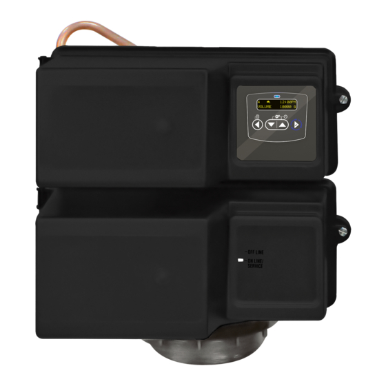
Installer manual Fleck 3900 NXT/NXT2 - Description Components description and location 3.4.1 With NXT controller and AC motor Upper power head Brine line Drain line Outlet Lower power head Injector Inlet 18 / 184 Ref. MKT-IM-015 / D - 28.08.2020... - Page 19 Installer manual Fleck 3900 NXT/NXT2 - Description Camshaft Micro-switches Brine valve AC motor Upper piston NXT controller Lower piston AC motor Micro-switches Camshaft Ref. MKT-IM-015 / D - 28.08.2020 19 / 184...
- Page 20 Installer manual Fleck 3900 NXT/NXT2 - Description Status LED Display Diagnostic button Setting button Shift button Regeneration button 20 / 184 Ref. MKT-IM-015 / D - 28.08.2020...
-
Page 21: With Nxt Controller And Dc Motor
Installer manual Fleck 3900 NXT/NXT2 - Description 3.4.2 With NXT controller and DC motor Info As of April 2019, NXT valves are supplied with 24 VDC motor. This motor is equipped with an AC-DC converter allowing it to be powered with 24 VAC or 24 VDC. Therefore, when used with NXT boards which require 24 VAC power supply and therefore send... - Page 22 Installer manual Fleck 3900 NXT/NXT2 - Description Status LED Display Diagnostic button Setting button Shift button Regeneration button 22 / 184 Ref. MKT-IM-015 / D - 28.08.2020...
- Page 23 Installer manual Fleck 3900 NXT/NXT2 - Description AC to DC converter Camshaft Micro-switches Brine valve DC motor Upper piston NXT controller Lower piston DC motor Micro-switches Camshafts Ref. MKT-IM-015 / D - 28.08.2020 23 / 184...
-
Page 24: With Nxt2 Controller And Dc Motor
Installer manual Fleck 3900 NXT/NXT2 - Description 3.4.3 With NXT2 controller and DC motor AC to DC converter Camshaft Micro-switches Brine valve DC motor Upper piston Outlet NXT2 controller Lower piston DC motor Micro-switches Camshaft 24 / 184 Ref. MKT-IM-015 / D - 28.08.2020... - Page 25 Installer manual Fleck 3900 NXT/NXT2 - Description Upper power head Brine line Drain line Outlet Lower power head Injector Inlet Ref. MKT-IM-015 / D - 28.08.2020 25 / 184...
-
Page 26: System Regeneration Cycle
Installer manual Fleck 3900 NXT/NXT2 - Description System regeneration cycle Info This valve allows to do filtration, down flow and up flow regenerations. 3.5.1 Downflow regeneration cycle (5-cycles operation) Service — normal use Untreated water is directed down through the resin bed and up through the riser tube. The hardness ions attach themselves to the resin and are removed from the raw water being exchanged on the resin beads by sodium ions. - Page 27 Installer manual Fleck 3900 NXT/NXT2 - Description SERVICE NORMAL USE BACKWASH Outlet Inlet Outlet Inlet Drain Valve Valve BRINE DRAW & SLOW RINSE RAPID RINSE Outlet Inlet Outlet Inlet Drain Drain Valve Valve From brine tank BRINE TANK REFILL PAUSE & DELAY...
-
Page 28: Upflow Regeneration Cycle (5-Cycles Operation)
Installer manual Fleck 3900 NXT/NXT2 - Description 3.5.2 Upflow regeneration cycle (5-cycles operation) Service — normal use Untreated water is directed down through the resin bed and up through the riser tube. The hardness ions attach themselves to the resin and are removed from the raw water being exchanged on the resin beads by sodium ions. - Page 29 Installer manual Fleck 3900 NXT/NXT2 - Description PAUSE & DELAY BRINE DRAW & SLOW RINSE Outlet Inlet Outlet Inlet Drain Valve Valve From brine tank BACKWASH RAPID RINSE Outlet Inlet Outlet Inlet Drain Drain Valve Valve SERVICE BRINE REFILL NORMAL USE...
-
Page 30: Filter Cycle (3-Cycles Operation)
Installer manual Fleck 3900 NXT/NXT2 - Description 3.5.3 Filter cycle (3-cycles operation) Service — normal use Untreated water is directed down through the filter media and up through the riser tube. The impurities are retained by the media. The water is filtered as it passes through the media. - Page 31 Installer manual Fleck 3900 NXT/NXT2 - Description SERVICE C1/C2 NORMAL USE BACKWASH Outlet Inlet Outlet Inlet Drain Valve Valve C3/C4 SERVICE RAPID RINSE NORMAL USE Outlet Inlet Outlet Inlet Drain Valve Valve Ref. MKT-IM-015 / D - 28.08.2020 31 / 184...
-
Page 32: Injector Block Position For Df And Uf Configurations
Installer manual Fleck 3900 NXT/NXT2 - Description Injector block position for DF and UF configurations 32 / 184 Ref. MKT-IM-015 / D - 28.08.2020... -
Page 33: System Sizing
Installer manual Fleck 3900 NXT/NXT2 - System sizing System sizing Recommended Injector/DLFC/BLFC-Valve configuration Brine Tank Resin Injector DLFC BLFC syst. Diameter volume [in] Color Color [gpm] DF [gpm] UF [gpm] 3900/ 283 - 424 Green Green 20.0 1800 284 - 425 25.0... -
Page 34: Determining The Required Volume Of Resin
Installer manual Fleck 3900 NXT/NXT2 - System sizing Service velocity Inlet water hardness °f °dH [bed volume per hour] [mg/l as CaCO °TH 8 - 20 >450 >45 >25.2 Caution - material Risk of leakage due to unrespected service velocity ! Failure to respect the service velocity will lead to hardness leakage or even total softener inefficiency. -
Page 35: Resin Exchange Capacity And Capacity Of The Unit
Installer manual Fleck 3900 NXT/NXT2 - System sizing Knowing this required volume of resin, it is possible now to determine the needed tank. Note that at least a third of the total volume of the tank must be kept as free space so that the bed expansion during backwash is sufficient to ensure correct cleaning of the resin. -
Page 36: Valve Configuration
Installer manual Fleck 3900 NXT/NXT2 - System sizing Salt amount Corresponding resin °f.m °dH.m [g/L exchange capacity [per L [per L resin resin resin [g/L ] as CaCO resin 3.97 75.3 7.53 4.21 To calculate the system mass capacity: × C... -
Page 37: Cycle Time Calculation
Installer manual Fleck 3900 NXT/NXT2 - System sizing To determine the backwash flow rate: = Fs with: backwash backwash : backwash flow rate [m backwash : backwash velocity [m/h] backwash S: Tank cross section area [m The DLFC installed on the valve has to limit the backwash flow rate to the above calculated flow rate. - Page 38 Installer manual Fleck 3900 NXT/NXT2 - System sizing To calculate the backwash duration: = (N × BV) / Q with: backwash BVbw DLFC : backwash duration [min] backwash : number of bed volume for backwash BVbw BV: bed volume [L]...
-
Page 39: Salt Amount Definition
Installer manual Fleck 3900 NXT/NXT2 - System sizing Depending on the valve type, the fast rinse flow rate is controlled by the DLFC or it has about the same flow rate as in service. The fast rinse velocity can be the same as the service velocity, and the volume of water to be used for the fast rinse is generally between 1 and 10 BV depending on the salt dosage. -
Page 40: 1800 Injector Flow Rates
Installer manual Fleck 3900 NXT/NXT2 - System sizing 4.4.1 1800 Injector flow rates INJECTOR 5 Total Rinse Draw Inlet pressure [bar] INJECTOR 6 Total Rinse Draw Inlet pressure [bar] INJECTOR 7 Total Rinse Draw Inlet pressure [bar] 40 / 184... - Page 41 Installer manual Fleck 3900 NXT/NXT2 - System sizing INJECTOR 8 Total Rinse Draw Inlet pressure [bar] INJECTOR 9 Total Draw Rinse Rinse Draw Inlet pressure [bar] INJECTOR 10 Total Rinse Draw Inlet pressure [bar] Ref. MKT-IM-015 / D - 28.08.2020...
-
Page 42: Installation
Installer manual Fleck 3900 NXT/NXT2 - Installation Installation CAUTION Risk of injury due to electrical shock or pressurized elements ! It is strictly forbidden for not qualified personal, to accede to system’s internal parts to perform any kind of technical action. -
Page 43: Water
Installer manual Fleck 3900 NXT/NXT2 - Installation • keep the media tank in an upright position. Do not turn on its side, upside down, or drop it. Turning the tank upside down may cause media to enter the valve or might clog the upper screen;... -
Page 44: Integration Constraints
Installer manual Fleck 3900 NXT/NXT2 - Installation • All plastic connections should be hand-tightened. PTFE (plumber’s tape) may be used on connections that do not use an O-ring seal. Do not use pliers or pipe wrenches; • existing plumbing should be in a good shape and free from limescale. In case of doubt, it is preferable to replace it;... -
Page 45: Top-Mounted Valve Installation
Installer manual Fleck 3900 NXT/NXT2 - Installation See chapter Components description and location [ → Page 18] to identify the connections. When pressurized, any composite tank will expand both vertically and circumferential. In order to compensate the vertical expansion, the piping connections to the valve must be flexible enough to avoid overstress on the valve and tank. - Page 46 Installer manual Fleck 3900 NXT/NXT2 - Installation • failure to provide enough vertical compensation may lead to different kinds of damage, either on the valve thread which is connected to the tank, or on the female thread connection of the tank.
-
Page 47: Side-Mounted Valve Installation
Installer manual Fleck 3900 NXT/NXT2 - Installation 5.5.2 Side-mounted valve installation Valid for location having a reduced height. Inlet Inlet shutoff Manual shutoff valve bypass Rubber expansion joint Outlet Fleck meter Tank Outlet shutoff Drain line Support tripod Rubber expansion joint •... -
Page 48: Block Diagram And Configuration Example
Installer manual Fleck 3900 NXT/NXT2 - Installation Block diagram and configuration example Block diagram Pressure gauge Main inlet User’s line Check valve to prevent water harm Filter cartridge By-pass Pressure regulator Meter Suggested options Drain line Brine line Valve Brine tank... - Page 49 Installer manual Fleck 3900 NXT/NXT2 - Installation Valve 3900 NXT Upper distributor A-2742-FU SBV 28182 Side mounted adapter 18926 Tank C-4278-F7 Lower distributor A-2742-FL Air check 18979 Ref. MKT-IM-015 / D - 28.08.2020 49 / 184...
-
Page 50: Regeneration Flows
Installer manual Fleck 3900 NXT/NXT2 - Installation Regeneration flows Mandatory For all multiple tank systems NBP valve version must be used ! Info In this chapter, systems up to four valves are used to describe and illustrate the different multiple valves systems, even if the described system with time NXT2 may control more than four valves. -
Page 51: Single Valve (System 4)
Installer manual Fleck 3900 NXT/NXT2 - Installation 5.7.1 Single valve (System 4) As named, this system works with only one valve. The regen can be initiated upon the treated volume (delayed or immediate), time clock mode or an external remote regen signal or day of week (NXT2 controller only). -
Page 52: Duplex Alternating Immediate System (System 7)
Installer manual Fleck 3900 NXT/NXT2 - Installation During normal operation, the controllers of each valve display the time of day and the volume of water remaining. The remaining volume is the total volume of the system. The remaining volume displayed drops with water consumption to reach zero. When this happens, if no other valve is regenerating, the lead valve starts regeneration while sending out a regeneration lock out signal to all other valves of the system. -
Page 53: Duplex Alternating Delayed System (System 8) (Nxt2 Only)
Installer manual Fleck 3900 NXT/NXT2 - Installation Inlet Outlet Valve Meter Tank Check valve 5.7.5 Duplex alternating delayed system (System 8) (NXT2 only) This system works with 2 valves and a meter. During normal operation, the controller of each valve displays the time of day and the volume of water remaining. -
Page 54: Multiple Valves, System On-Demand (System 14)
Installer manual Fleck 3900 NXT/NXT2 - Installation Inlet Outlet Valve Tank Check valve Service Service Service Stand-By 100% Meter 5.7.7 Multiple valves, system on-demand (System 14) This system type may be used to build systems from 2 to 4 valves for NXT controller, 2 to 8 valves for NXT2. - Page 55 Installer manual Fleck 3900 NXT/NXT2 - Installation Inlet Outlet Valve Tank Check valve First trip Service Stand-By Stand-By point (primary Meter tank) Total flow rate is split between two meters The flow rate demand decreases below the first trip point. The tank returns to standby.
- Page 56 Installer manual Fleck 3900 NXT/NXT2 - Installation Inlet Outlet Valve Tank Check valve Service Service Service Stand-By Meter Total flow rate is split between three meters The third tank returns to standby as demand decreases and returns below the second trip point.
- Page 57 Installer manual Fleck 3900 NXT/NXT2 - Installation Inlet Outlet Valve Check valve Tank 4th in 3rd in 2nd in 1st in standby standby standby standby (Primary Meter valve) 5.7.7.2 System operation in regeneration The primary tank regenerates when its remaining volume becomes zero. The next tank with the least remaining volume becomes the new primary tank.
-
Page 58: Electrical Connections
Installer manual Fleck 3900 NXT/NXT2 - Installation Electrical connections CMN: Common Solenoid valve Flow meter Sw1: Valve homing switch GND: Ground Sw2: Valve step switch HCAM: Valve homing cam Sw3: Lower drive switch (only for 2910 and 3900 valves) LCK:... -
Page 59: Nxt Controller Connections
Installer manual Fleck 3900 NXT/NXT2 - Installation 5.8.1 NXT controller connections Ref. MKT-IM-015 / D - 28.08.2020 59 / 184... -
Page 60: Nxt2 Controller Connections
Installer manual Fleck 3900 NXT/NXT2 - Installation 5.8.2 NXT2 controller connections Caution - material Risk of non-function due to wrong connection ! Do not connect 24V (AC or DC) power supply on the Lower piston switch connector P17. 60 / 184... -
Page 61: Nxt Controller Connections For Multiple Valves
Installer manual Fleck 3900 NXT/NXT2 - Installation 5.8.3 NXT controller connections for multiple valves 2 controllers NXT Duplex system 5, 6, 7, 9 & 14 3 controllers NXT Triplex system 5, 6, 9 & 14 4 controllers NXT Quadriplex system 5, 6, 9 & 14... -
Page 62: Nxt2 Controller Connections For Multiple Valves
Installer manual Fleck 3900 NXT/NXT2 - Installation 5.8.4 NXT2 controller connections for multiple valves Mandatory Use CAT5 (with RJ45 connector) or better twisted pair cables with a maximum length of 30 meters ! 2 controllers NXT2 Duplex system 5, 6, 7, 8, 9 & 14 3 controllers NXT2 Triplex system 5, 6, 9 &... -
Page 63: Bypassing
Installer manual Fleck 3900 NXT/NXT2 - Installation Bypassing A bypass valve system should be installed on all water conditioning systems. Bypass valves isolate the softener from the water system and allow unconditioned water to be used. Service or routine maintenance procedures may also require that the system is bypassed. -
Page 64: Overflow Line Connection
Installer manual Fleck 3900 NXT/NXT2 - Installation Mandatory Waste connections or the drain outlet shall be designed and constructed to provide connection to the sanitary waste system through an air-gap of 2 pipe diameters or 100.6 mm (4"), whichever is larger. -
Page 65: Brine Line Connection
Installer manual Fleck 3900 NXT/NXT2 - Installation Overflow fitting Drain tubing Secure hose in place Air gap Drain Caution - material Risk of flooding due to lack of floor drain ! Floor drain is always recommended to avoid flooding in case of overflow. -
Page 66: Programming
Installer manual Fleck 3900 NXT/NXT2 - Programming Programming NXT controller 6.1.1 Display 1. System type • 4: single valve; • 5:Multiple valves, parallel interlock system, 2 to 4 valves; • 6: Multiple valves, parallel series regeneration system, 2 to 4 valves; • 7: duplex alternating immediate system, 2 valves;... -
Page 67: Commands
Installer manual Fleck 3900 NXT/NXT2 - Programming 6.1.2 Commands Info At any time, press D to return to the home screen without saving. Menus are displayed in a defined and incremental order. If none of the buttons are pushed for 5 minutes in the Programming mode, or if there is a power failure, the controller returns to Service mode without saving. - Page 68 Installer manual Fleck 3900 NXT/NXT2 - Programming Parameter Options Definition Note FEED WATER 1 to 1’999 Milligram CaCO This screen will only display on the HARDNESS lead unit for system type 6. For all other system types, it will display for all units.
- Page 69 Installer manual Fleck 3900 NXT/NXT2 - Programming Mandatory For a timeclock valve, this value must be set ! Info For metered valves, calendar override parameter would trigger a regeneration only if the volumetric control did not start a regeneration before calendar override period elapsed.
- Page 70 Installer manual Fleck 3900 NXT/NXT2 - Programming 6.1.5.1 Master programming mode chart Parameter Options Definition Note LANGUAGE ENGLISH English (default) FRANCAIS French DEUTSCH German ITALIANO Italian ESPANOL Spanish SYSTEM TYPE Single unit (default) 1 unit. Parallel interlock 2 to 4 units. Parallel series...
- Page 71 Installer manual Fleck 3900 NXT/NXT2 - Programming Parameter Options Definition Note REMOTE SIGNAL OFF to 99 OFF (default) This screen will not be displayed for START minutes system type 14. This screen will only display on the lead (#1) unit for system types 6 & 7.
- Page 72 Installer manual Fleck 3900 NXT/NXT2 - Programming Parameter Options Definition Note REGENERATION 00:00:00 Hour Regeneration time will not appear TIME to 23:59:59 02:00 AM (default) unless regeneration day override is on or vale is programmed as time clock or meter delayed.
- Page 73 Installer manual Fleck 3900 NXT/NXT2 - Programming Parameter Options Definition Note CPO AUX RELAY 1 to 9’999 Only displayed if chemical pump is VOLUME enabled in previous screen. Activate the relay output during a CPO AUX RELAY 00:00:00 Hour service based upon the volume of TIME to 02:00:00...
- Page 74 Installer manual Fleck 3900 NXT/NXT2 - Programming 6.1.5.4 System type Select the system in which the valve(s) operate(s). Options: • 4 (default): single valve; • 5: multiple valves, parallel interlock system; • 6: multiple valves, parallel series regeneration system; • 7: duplex alternating immediate system;...
- Page 75 Installer manual Fleck 3900 NXT/NXT2 - Programming 6.1.5.6 System size Set the number of valves to be connected (2 to 4 valves) in the system. Info Only visible in multiple valve systems and only present on the master #1 valve. Options: •...
- Page 76 Installer manual Fleck 3900 NXT/NXT2 - Programming 1. Set valve type at 3900 with 2. Press to validate the selection and advance to the next parameter. 6.1.5.9 Regenerant flow Set the direction of flow during the brine draw cycle. Info The availability depends on the valve type programmed in the previous step.
- Page 77 Installer manual Fleck 3900 NXT/NXT2 - Programming 6.1.5.11 Display format Set the system unit to be used. Options: • US GALLONS (default): volume in gallons, time display 2 x 12 hours, hardness in grains; • EU-METRIC-LITRES: volume in litre, time display 24 hours and hardness depends on the...
- Page 78 Installer manual Fleck 3900 NXT/NXT2 - Programming 6.1.5.14 Feed water hardness Info Only displayed if valve is programmed as volumetric. This screen will only display on the lead (#1) unit for system type 6. For all other system type, it will display for all units.
- Page 79 Installer manual Fleck 3900 NXT/NXT2 - Programming 1. Set the trip point 2 flow rate with ð Can be adjusted from trip point 1+1 to 3998 l/min. 2. Press to validate the selection and advance to the next parameter. 3. Set the trip point 2 delay with ð...
- Page 80 Installer manual Fleck 3900 NXT/NXT2 - Programming 1. Adjust the number of days with Without calendar forcing. 2. Press to validate the selection and advance to the next parameter. ð Can be adjusted from: Forcing every 3 days. 1 to 99 days for timeclock regeneration;...
- Page 81 Installer manual Fleck 3900 NXT/NXT2 - Programming 1. Adjust the cycle time with 1. Backwash: 10 min (default). 2. Press to validate the selection and advance to the next parameter. 3. Repeat for each cycle. 2. Draw/Slow rinse: 1 h 00 min (default). 3. Fast rinse: 10 min (default).
- Page 82 Installer manual Fleck 3900 NXT/NXT2 - Programming 1. Activate the relay with Disabled. 2. Press to validate the selection and advance to the next parameter. 3. Set the relay activation time with Relay enabled at the beginning of regeneration. 4. Press to validate the selection and advance to the next parameter.
- Page 83 Installer manual Fleck 3900 NXT/NXT2 - Programming 1. Activate the relay with Disabled. 2. Press to validate the selection and advance to the next parameter. 3. Set the relay activating volume with Relay enabled every 20 litre. 4. Press to validate the selection and advance to the next parameter.
- Page 84 Installer manual Fleck 3900 NXT/NXT2 - Programming 1. Set the maximum flow rate with Example: 290 L/min. 2. Press to validate the selection and advance to the next parameter. 3. Set the number of litres per pulse(s) with Example: 1 litre for 1 pulse.
- Page 85 Installer manual Fleck 3900 NXT/NXT2 - Programming 6.1.6.3 Peak flow rate Info The controller registers the highest flow rate since the last regeneration. 6.1.6.4 Totalizer Info The controller registers the total volume of treated water that passes through the meter since start-up (or last hard reset).
- Page 86 Installer manual Fleck 3900 NXT/NXT2 - Programming 6.1.6.7 Volume remaining Info Shows the volume remaining for the valve where controller is installed, excepted for system 6 where it shows the volume remaining of the complete system. This parameter is adjustable, allowing adjustment of the volume remaining after any servicing of the system.
- Page 87 Installer manual Fleck 3900 NXT/NXT2 - Programming 6.1.7 Resetting the controller Mandatory Once you have completed this operation, check all programming steps ! Info There are two options to reset: partial and hard reset. Partial reset will set all the parameters to default values, except flow meter totalizer volume in diagnostic mode.
- Page 88 Installer manual Fleck 3900 NXT/NXT2 - Programming NXT2 Controller Info All information of this chapter correspond to software version 1.0.1387. 6.2.1 Display 1. System type • 4: Single valve; • 5: Multiple valves, parallel interlock system, 2 to 8 valves; • 6: Multiple valves, parallel series regeneration system, 2 to 8 valves;...
- Page 89 Installer manual Fleck 3900 NXT/NXT2 - Programming 3. Valve status • Initializing: after a power failure or a change in the programming, the controllers initializes for approximately 30 seconds; • Lock windows: the controller is inside the lockout windows; • Lock remote: the controller is acquiring the lockout remote signal;...
- Page 90 Installer manual Fleck 3900 NXT/NXT2 - Programming 6.2.2 Commands 6.2.2.1 Menu commands Info At all menus, press to return to previous screen without saving. Menus are displayed in a defined and incremental order. Editable digit is marked by two triangles (Cursor).
- Page 91 Installer manual Fleck 3900 NXT/NXT2 - Programming 6.2.3 Time of day menu Mandatory In multiple valve systems, set the time of day on the lead valve (#1) ! The time of day will be automatically updated on the other valves in the system within 10 seconds.
- Page 92 Installer manual Fleck 3900 NXT/NXT2 - Programming 6.2.4 Basic programming mode 6.2.4.1 Basic programming mode chart Parameter Options Definition Note DAY OVERRIDE / OFF to 99 This screen will not be displayed if day TIME DRIVEN of week regeneration has been selected.
- Page 93 Installer manual Fleck 3900 NXT/NXT2 - Programming Info For metered valves, day override parameter would trigger a regeneration, only if the volumetric control did not start a regeneration before calendar override period elapsed. Each volumetric regeneration happening reset the calendar override delay.
- Page 94 Installer manual Fleck 3900 NXT/NXT2 - Programming Info This parameter is visible only in meter immediate/delayed mode 1. Adjust the volume with and . 2. Press to validate the selection and advance to the next parameter. 6.2.4.6 Push settings This parameter allows to push and copy settings from the one unit to all other connected units.
- Page 95 Installer manual Fleck 3900 NXT/NXT2 - Programming Parameter Options Definition Note ASSISTANCE 12 characters maximum. NAME 1 ASSISTANCE NAME 2 ASSISTANCE 14 characters maximum. PHONE SYSTEM Single unit (default) 1 unit. Parallel interlock 2 to 8 units. Parallel series regeneration Alternating immediate 2 units. Alternating delayed Parallel with standby 2 to 8 units.
- Page 96 Installer manual Fleck 3900 NXT/NXT2 - Programming Parameter Options Definition Note REGEN. FLOW DOWN FLOW Down flow softener (default) UP FLOW Up flow softener Do not use for 2510, 2750 and 2850 valve types. FILTER Filter REGEN. TYPE TIME CLOCK Time clock System 4 and 6 only.
- Page 97 Installer manual Fleck 3900 NXT/NXT2 - Programming Parameter Options Definition Note RESERVE WEEKLY (default) This screen will only display when RESERVE regeneration type selected is softener meter delayed. VARIABLE RESERVE FIXED% FIXED VOLUME FIXED% 0 to 50 This screen will only display when...
- Page 98 Installer manual Fleck 3900 NXT/NXT2 - Programming Parameter Options Definition Note DAY OVERRIDE / OFF to 99 This screen will not be displayed if TIME DRIVEN day of week regeneration has been selected. Days between regenerations only for metered regeneration types.
- Page 99 Installer manual Fleck 3900 NXT/NXT2 - Programming Parameter Options Definition Note METER TYPE GENERIC Default flow meter type is based on the valve type; 0.75" PADDLE (default for 2510) This screen will only display when 0.75" TURBINE regeneration type selected is 1.0"...
- Page 100 Installer manual Fleck 3900 NXT/NXT2 - Programming Parameter Options Definition Note AUX. 1: CYCLE Service position Only displayed if “Cycle based” is BASED chosen for auxiliary 1; Backwash position Activate or de-activate for each Draw and slow rinse position ( = deactivated; position = activated).
- Page 101 Installer manual Fleck 3900 NXT/NXT2 - Programming Parameter Options Definition Note AUXILIARY 2 STANDBY Activates relay from beginning of regeneration and during standby phase. (default) ALARM BASED Any alarm or error detected by the controller will start signal output from Auxiliary relay#2.
- Page 102 Installer manual Fleck 3900 NXT/NXT2 - Programming Parameter Options Definition Note AUX. 2: VOLUME 0 to MAX Litre Only displayed if “volume based” is BASED – chosen for auxiliary 1; VOLUME - L Volume range depend on capacity; Even if maximum theoretical programmable value is 999999 the controller will take the unit capacity as maximum volume.
- Page 103 Installer manual Fleck 3900 NXT/NXT2 - Programming 6.2.5.4 Language Select the displayed language. Options: • English (default); • French; • German; • Italian; • Spanish; • Dutch; • Portuguese. 1. Select the language with 2. Press to validate the selection and advance to the next parameter.
- Page 104 Installer manual Fleck 3900 NXT/NXT2 - Programming 1. Edit assistance phone using and ; ð Each character can be chose from 0 to 9 or stay empty; 2. Press to validate the selection and advance to the next parameter. 6.2.5.7 System type Select the system in which the valve(s) operate(s).
- Page 105 Installer manual Fleck 3900 NXT/NXT2 - Programming Info Only visible in system 14, and on master valve, identified by on the controller screen. Depending on the number of tanks used in the system, there might up to 7 trip point to set up (for 8 tanks systems).
- Page 106 Installer manual Fleck 3900 NXT/NXT2 - Programming • down flow (default); • up flow (do not use for 2510, 2750 and 2850 valve types); • filter. 1. Select regeneration flow with 2. Press to validate the selection and advance to the next parameter.
- Page 107 Installer manual Fleck 3900 NXT/NXT2 - Programming 6.2.5.14 Volume override/ Volumetric Set the volume of water between 2 cleaning cycles. Info Available only for filter metered systems. 1. Set the volume override with and ; ð Can be adjusted from 0 to 9’999’999 litres;...
- Page 108 Installer manual Fleck 3900 NXT/NXT2 - Programming Info This screen is displayed only for metered systems. Based upon the system capacity, reserve and inlet water hardness, the controller calculates the volume of water that the system can treat between 2 regenerations.
- Page 109 Installer manual Fleck 3900 NXT/NXT2 - Programming Options: • weekly reserve (default); • variable reserve; • fixed%; • fixed volume. 1. Select reserve type with 2. Press to validate the selection and advance to the next parameter. Fixed% Set the percentage of the total system capacity used to calculate the safety reserve capacity.
- Page 110 Installer manual Fleck 3900 NXT/NXT2 - Programming 6.2.5.19 Remote regeneration Select the regeneration type for remotely started regeneration (external dry contact input, see chapter NXT2 controller connections [ → Page 60]). Info This mode can be combined with the other methods of regeneration The remotely started regenerations overrule the other regeneration type once the signal is acquired.
- Page 111 Installer manual Fleck 3900 NXT/NXT2 - Programming • Tuesday; • Wednesday; • Thursday; • Friday; • Saturday. 1. Select the days for regeneration with and ; ð Multi-selection is possible; ð Not selected days are marked by and selected days are marked by 2.
- Page 112 Installer manual Fleck 3900 NXT/NXT2 - Programming 1. Adjust the time of regeneration with 2. Can be adjusted from: 00:00 to 23:59HR; 3. Press to validate the selection and advance to the next parameter. 6.2.5.24 Lock window Set Lock Window: Enable lock windows then select the desired Lock Start time and Lock End time.
- Page 113 Installer manual Fleck 3900 NXT/NXT2 - Programming Info Lock Window #2 settings are accessible only if lock windows #1 is on. 1. Enable lock window with Lock window #2 activated. 2. Press to validate the selection and advance to the next parameter. 3. Set lock start time with Lock window #2 starts at...
- Page 114 Installer manual Fleck 3900 NXT/NXT2 - Programming 1. Adjust the cycle time with 1. Backwash: 10 min (default). ð Can be adjusted from: 0 to 240 minutes; 2. Press to validate the selection and advance to the next parameter; 2. Draw: 60 min (default).
- Page 115 Installer manual Fleck 3900 NXT/NXT2 - Programming 1. Select the meter type with 2. Press to validate the selection and advance to the next parameter. Generic meter Set the generic meter settings. Info Only visible if "generic" was selected as meter type in the previous step.
- Page 116 Installer manual Fleck 3900 NXT/NXT2 - Programming 1. Set continuous flow on with Continuous flow detect activated. 2. Press to validate the selection and advance to the next parameter; 3. Adjust flow rate with and ; Continuous flow detect - 4.
- Page 117 Installer manual Fleck 3900 NXT/NXT2 - Programming 1. Choose the options of relay with Activated during selected cycle step. ð Unselected cycle are marked by ð Activated cycles are marked with a ð Multi-selection is possible; 2. Press to validate the selection and advance to the next parameter.
- Page 118 Installer manual Fleck 3900 NXT/NXT2 - Programming 1. Set the relay Start time #2 with Activated 12 minutes after the regeneration started. 2. Can be adjusted from: end time #1 +1 to the total regeneration duration minus 1 minute; TIME BASED - START TIME #2.
- Page 119 Installer manual Fleck 3900 NXT/NXT2 - Programming Info Available only for multi-valves systems. The ability to transmit settings from one unit to all other connected units. After push settings are complete, you may still make unique changes to individual units.
- Page 120 Installer manual Fleck 3900 NXT/NXT2 - Programming 1. Select the lock setting option with 2. Press to validate the selection. 6.2.5.32 Parameters saving Info When the last parameter is set and the button pressed (after lock settings), the controller updates the database based on the new programming.
- Page 121 Installer manual Fleck 3900 NXT/NXT2 - Programming 6.2.6.4 Totalizer Info The controller registers the total volume of treated water that passes through the meter since start-up (or last hard reset). 1. To reset, press and hold the buttons for 5 seconds until the display shows zero.
- Page 122 Installer manual Fleck 3900 NXT/NXT2 - Programming 6.2.6.9 Software version Info Shows the version of the software loaded in the controller. Mandatory In case of use of multiple valves system, verify the controller’s software compatibility ! 6.2.6.10 Number of regeneration Info Shows number of regeneration since installation.
- Page 123 Installer manual Fleck 3900 NXT/NXT2 - Programming 6.2.6.14 Sunday average daily usage Info Shows average water consumption on Sunday. 6.2.6.15 Sunday- daily usage Info Shows water consumption for the last 20 Sunday. 6.2.6.16 Monday average daily usage Info Shows average water consumption on Monday.
- Page 124 Installer manual Fleck 3900 NXT/NXT2 - Programming 6.2.6.19 Tuesday- daily usage Info Shows water consumption for the last 20 Tuesday. 6.2.6.20 Wednesday average daily usage Info Shows average water consumption on Wednesday. 6.2.6.21 Wednesday- daily usage Info Shows water consumption for the last 20 Wednesday.
- Page 125 Installer manual Fleck 3900 NXT/NXT2 - Programming 6.2.6.24 Friday average daily usage Info Shows average water consumption on Friday. 6.2.6.25 Friday- daily usage Info Shows water consumption for the last 20 Friday. 6.2.6.26 Saturday average daily usage Info Shows average water consumption on Saturday.
- Page 126 Installer manual Fleck 3900 NXT/NXT2 - Programming Info There are two options to reset: reset to factory defaults or reset to Non-Factory Defaults. Reset to factory defaults will set all the parameters to factory default values. Reset to non-factory defaults will set all the parameters to previously saved default values.
- Page 127 Installer manual Fleck 3900 NXT/NXT2 - Commissioning Commissioning Info This chapter is available for standard regeneration flows. Contact your supplier if the actual regeneration is not standard and if you need assistance. Water filling, draining and waterproofness inspection 7.1.1 Activating a single valve system (System 4) 1.
- Page 128 Installer manual Fleck 3900 NXT/NXT2 - Commissioning 12. With the brine tank completely refilled and full of salt, adjust the safety brine valve in the brine well. Make sure the overflow elbow is installed above the float level and the discharge point.
- Page 129 Installer manual Fleck 3900 NXT/NXT2 - Commissioning Depending on the conditions of use, the softener type, the type of ion exchanger and the disinfectant available, a choice can be made among the following methods. 7.2.2 Sodium or calcium hypochlorite These materials are satisfactory for use with polystyrene resins, synthetic gel zeolite, greensand and bentonites.
- Page 130 Installer manual Fleck 3900 NXT/NXT2 - Operation Operation Display 8.1.1 NXT controller 8.1.1.1 During service • Single valve in service in timeclock mode: • single valve in service in volume immediate or delayed mode: • lead valve in regeneration queued in interlock system: •...
- Page 131 Installer manual Fleck 3900 NXT/NXT2 - Operation • single valve in service in volume immediate or delayed mode: • lead valve in regeneration queued in interlock system: • window lock activated in serial regeneration system: • remote lock activated in serial regeneration system: 8.1.2.2...
- Page 132 Installer manual Fleck 3900 NXT/NXT2 - Operation • cycle step #4, time remaining 2 hours 40 min: Once in position: • the timer advance to regeneration cycle step #5: During transition to cycle: • cycle step #5, time remaining 15 min: Once in position: 8.1.3 LED status Blue the unit is in service and no errors detected;...
- Page 133 Installer manual Fleck 3900 NXT/NXT2 - Operation ð For NXT2: The blue LED and the symbol on the valve state flash. Info To cancel: press (for NXT) or (for NXT2) again. For NXT: The blue LED stop flashing and the letters SRV take place on the valve status.
- Page 134 Installer manual Fleck 3900 NXT/NXT2 - Maintenance Maintenance Mandatory Cleaning, maintenance and service operation shall take place at regular intervals and must be done by qualified personnel only in order to guarantee the proper functioning of the complete system. Report maintenance done in the Maintenance chapter of the User Guide document.
- Page 135 Installer manual Fleck 3900 NXT/NXT2 - Maintenance 9.1.3 Regeneration test 9.1.3.1 Valve used for softening 1. Check condition of brine tank and any associated equipment. 2. Check salt level in brine tank. 3. Initiate regeneration test. ð Check brine draw during brine draw stage.
- Page 136 Installer manual Fleck 3900 NXT/NXT2 - Maintenance Recommended maintenance plan 9.2.1 Valve used for softening Items 1 year 2 year 3 year 4 year 5 year Injector & filter Clean Clean Clean Clean Clean/ replace if necessary BLFC*** Clean Clean...
- Page 137 Installer manual Fleck 3900 NXT/NXT2 - Maintenance Items 1 year 2 year 3 year 4 year 5 year Valve Check Check Check Check Check watertightness Valve to piping Check Check Check Check Check watertightness * Wear parts - durability strongly affected by raw water quality and regeneration frequency.
- Page 138 Installer manual Fleck 3900 NXT/NXT2 - Maintenance 9.2.2 Valve used for filtration Items 1 year 2 year 3 year 4 year 5 year DLFC*** Clean Clean Clean Clean Clean/ replace if necessary Bypass (if Clean Clean Clean Clean Clean/replace present,...
- Page 139 Installer manual Fleck 3900 NXT/NXT2 - Maintenance Recommendations 9.3.1 Use original spare parts Caution - material Risk of damage due to use of non-genuine spare parts ! To ensure correct operation and safety of the device, only use original spare parts and accessories recommended by the manufacturer.
- Page 140 Installer manual Fleck 3900 NXT/NXT2 - Maintenance 9.4.2 Power head and/or motor replacement 9.4.2.1 Valve with NXT controller Info As the DC motor is equipped with an AC to DC converter, AC and DC motors can be used with the NXT controller.
- Page 141 Installer manual Fleck 3900 NXT/NXT2 - Maintenance AC motor DC motor Ref. MKT-IM-015 / D - 28.08.2020 141 / 184...
- Page 142 Installer manual Fleck 3900 NXT/NXT2 - Maintenance 9.4.2.2 Valve with NXT2 controller Caution - material Risk of damage due to AC motor use ! Use only DC motor with NXT2 controller. 1. Using a flat screwdriver, unscrew (1) and open the cover (2).
- Page 143 Installer manual Fleck 3900 NXT/NXT2 - Maintenance DC motor Ref. MKT-IM-015 / D - 28.08.2020 143 / 184...
- Page 144 Installer manual Fleck 3900 NXT/NXT2 - Maintenance 9.4.3 Lower power head motor replacement Caution - material Risk of damage due to AC motor use ! Use only DC motor with NXT2 controller. Info As the DC motor is equipped with a AC to DC converter, AC and DC motors can be used with the NXT controller.
- Page 145 Installer manual Fleck 3900 NXT/NXT2 - Maintenance AC motor DC motor Ref. MKT-IM-015 / D - 28.08.2020 145 / 184...
- Page 146 Installer manual Fleck 3900 NXT/NXT2 - Maintenance 9.4.4 NXT to NXT2 controller upgrade Mandatory As NXT2 controller functions only with DC motors, in case of NXT to NXT2 controller upgrade, the AC motor must be changed for a DC motor ! 1.
- Page 147 Installer manual Fleck 3900 NXT/NXT2 - Maintenance AC motor DC motor Ref. MKT-IM-015 / D - 28.08.2020 147 / 184...
- Page 148 Installer manual Fleck 3900 NXT/NXT2 - Maintenance 9.4.5 NXT2 controller replacement 1. Using a flat screwdriver, unscrew (1) and open the cover (2). 2. Press on the clips (3) and remove the controller (4). 3. Disconnect the controller (4). 4. Connect the new NXT2 controller (5), see NXT2 controller connections [ Page 60].
- Page 149 Installer manual Fleck 3900 NXT/NXT2 - Maintenance 9.4.6 Upper piston and/or seal and spacer kit replacement 1. Using a flat screwdriver, unscrew (1) and open the cover (2). 2. Using pliers, remove the clip (6) and the connecting pin (7). 3. Using a 32 mm wrench, unscrew (3).
- Page 150 Installer manual Fleck 3900 NXT/NXT2 - Maintenance Item Part number Description Packaging quantity 12682 Puller 2” 12683 Stuffer 2” 150 / 184 Ref. MKT-IM-015 / D - 28.08.2020...
- Page 151 Installer manual Fleck 3900 NXT/NXT2 - Maintenance 9.4.7 Lower piston and/or seal and spacer kit replacement 1. Using a flat screwdriver, unscrew (1) and open the cover (2). 2. Using pliers, remove the clip (5) and the connecting pin (6). 3. Using a 10 mm wrench, unscrew (3)
- Page 152 Installer manual Fleck 3900 NXT/NXT2 - Maintenance 152 / 184 Ref. MKT-IM-015 / D - 28.08.2020...
- Page 153 Installer manual Fleck 3900 NXT/NXT2 - Maintenance 9.4.8 Micro-switches replacement 1. Using a flat screwdriver, unscrew (1) and open the cover (2). 2. Using a Phillips screwdriver, unscrew (3) and extract the protection plates (4) and the micro- switches (5). 3. Reverse above procedure steps to rebuild.
- Page 154 Installer manual Fleck 3900 NXT/NXT2 - Maintenance 9.4.9 Cams replacement 1. Using a flat screwdriver, unscrew (1) and open the cover (2). 2. Remove the micro-switches (3), see Micro-switches replacement [ Page 153]. → 3. Disconnect the motor (4). 4. For NXT2 controller, open the controller (8) by pulling it. And for NXT controller, open the controller (8) unscrewing (7).
- Page 155 Installer manual Fleck 3900 NXT/NXT2 - Maintenance 9.4.10 Injector throat and washer cleaning 1. Using a 4 mm Allen wrench, unscrew (1). 2. Using a 24 mm wrench, remove the tube (10). 3. Using a 4 mm Allen wrench, unscrew (11) and remove the connector (9), the o-ring (8) and the injector nozzle (7).
- Page 156 Installer manual Fleck 3900 NXT/NXT2 - Maintenance 9.4.11 BLFC cleaning 1. Using a 34 mm wrench, remove the flow control housing (1) from the valve. 2. Using pliers, remove the retaining ring (6), the flow control retainer (5), the washer holder (3) and the washer (4).
- Page 157 Installer manual Fleck 3900 NXT/NXT2 - Maintenance 9.4.12 DLFC cleaning 1. Using a 5 mm Allen wrench, unscrew (1) and remove the housing (2). 2. Remove the cover plate (4) and the seat (6). 3. Remove the washers (5) from the seat (6).
- Page 158 Installer manual Fleck 3900 NXT/NXT2 - Maintenance 9.4.13 Valve on tank assembly 1. Lubricate the seals with approved silicone grease. 2. Spin the valve (1) onto the tank (2), ensuring the threads are not cross-threaded. 3. Rotate the valve (1) clockwise and freely, without using force until it comes to a stop.
- Page 159 Installer manual Fleck 3900 NXT/NXT2 - Troubleshooting Troubleshooting 10.1 Error detection Info It can take up to 30 seconds before an error can be detected and displayed. Mandatory All the errors must be displayed on each controller before they can be corrected ! •...
- Page 160 Installer manual Fleck 3900 NXT/NXT2 - Troubleshooting Problem Cause Solution Hard water By-pass valve is open. Close by-pass valve. No salt is in brine tank. Add salt to brine tank and maintain salt level above water level. Injector screen plugged.
- Page 161 Installer manual Fleck 3900 NXT/NXT2 - Troubleshooting Problem Cause Solution Excessive water in brine Plugged drain line flow control. Clean flow control. tank Plugged injector system. Clean injector and screen. Controller is not cycling. Replace controller. Foreign material in brine valve.
- Page 162 Installer manual Fleck 3900 NXT/NXT2 - Troubleshooting • system size: ex. programmed for 4 units, but there are only 2 units; • units of measure do not correspond between the different valves of the system; • wrong type of valve programmed.
- Page 163 Installer manual Fleck 3900 NXT/NXT2 - Troubleshooting • the motor is on but no encoder pulses are detected or CAM Switches change state within a given duration; – Verify microswitch wiring and that microswitches are working properly. • motor current exceeds thresholds;...
- Page 164 Installer manual Fleck 3900 NXT/NXT2 - Spare parts and options Spare parts and options 11.1 Valve parts list Item Part number Description Packaging quantity 60106-00 Piston assy 3150/3900 Upper DF 60106-10-US Piston assy 3150/3900 Upper UF 18022 S&S kit 2930/3150/3900 Upper 28339 S&S Kit 3150/3900 Upper HW...
- Page 165 Installer manual Fleck 3900 NXT/NXT2 - Spare parts and options Item Part number Description Packaging quantity 19677SP Screw 16387 VB plug ½” NPT 3150/3900 25580-20 DLFC 2in BSP - 2in BSP assy 20 GPM 3150/3900 25580-25 DLFC 2in BSP - 2in BSP assy 25 GPM 3150/3900...
- Page 166 Installer manual Fleck 3900 NXT/NXT2 - Spare parts and options 11.2 Power head parts list Item Part number Description Packaging quantity 26637 Cover assy 3150/3900 upper grey 26259 Transformer 24 VAC 105 VA (for 3900) 17967 Liquid tight 25353 Guide cable & cable assy 3900/9500...
- Page 167 Installer manual Fleck 3900 NXT/NXT2 - Spare parts and options Item Part number Description Packaging quantity 10872SP Screw motor mounting 17797 Bracket switch mounting 29212 Drive motor assy 3150/3900 24VAC/DC-50/60Hz 16494-04 Cam assy 3150/3900 upper UF grey 16494-05 Cam assy 3150/3900 upper DF black...
- Page 168 Installer manual Fleck 3900 NXT/NXT2 - Spare parts and options 11.3 Lower power head parts list Item Part number Description Packaging quantity 11080SP Screw Flat Head 11898SP Clip 3150/3900 18726-50SP Spacer indicator 19315 Indicator off line/on line 3900 11774SP Retaining ring...
- Page 169 Installer manual Fleck 3900 NXT/NXT2 - Spare parts and options Item Part number Description Packaging quantity 16086 Bracket motor 3900 40943 Harness 3200NT lower shown 11.4 1800 injector parts list Item Part number Description Packaging quantity 18702 Fitting, tube ½” NPT 5/8”...
- Page 170 Installer manual Fleck 3900 NXT/NXT2 - Spare parts and options Item Part number Description Packaging quantity 19677SP Screw 16341-01 Inj cover 1800 15246-01SP O-ring - 560CD 15128-04SP Injector nozzle 4 Green 15128-05SP Injector nozzle 5 Red 15128-06SP Injector nozzle 6 White...
- Page 171 Installer manual Fleck 3900 NXT/NXT2 - Spare parts and options Item Part number Description Packaging quantity 28388-1.5 BLFC assy 1” 1800 1.5 gpm 28388-2 BLFC assy 1” 1800 2 gpm 28388-3 BLFC assy 1” 1800 3 gpm 28388-3.5 BLFC assy 1” 1800 3.5 gpm 28388-5 BLFC assy 1”...
- Page 172 Installer manual Fleck 3900 NXT/NXT2 - Spare parts and options Item Part number Description Packaging quantity Plate, DLFC cover 11.7 Safety brine valves list Item Part number Description Packaging quantity 25453 SBV 2350 – without air check 28182 Union PVC female 1" to be glued - male 1" BSP 11.8...
- Page 173 Installer manual Fleck 3900 NXT/NXT2 - Spare parts and options Item Part number Description Packaging quantity A-TF30-025 Distribution system assy, tanks 30" A-TF36-025 Distribution system assy, tanks 36" A-3100-11C Adapter A-PIPE-90 Riser tube 1850 mm AB-GC8-30 Reducing bush ATD-H80-00 A-TH02-268 Lateral 268 mm, tanks 30"...
- Page 174 Installer manual Fleck 3900 NXT/NXT2 - Spare parts and options Item Part number Description Packaging quantity A-TH02-423 Lateral 423 mm, tanks 48" AD-H80-00 Hub cap 11.8.3 Flanged 6", tanks 42" - 63", TM & SM, bottom distribution, DN100 connections Item...
- Page 175 Installer manual Fleck 3900 NXT/NXT2 - Spare parts and options Item Part number Description Packaging quantity A-TH02-516 Lateral 516 mm, slots 0.2 mm, tanks 55" A-TH05-516 Lateral 516 mm, slots 0.5 mm, tanks 55" A-TH02-578 Lateral 578 mm, slots 0.2 mm, tanks 63"...
- Page 176 Installer manual Fleck 3900 NXT/NXT2 - Spare parts and options Item Part number Description Packaging quantity A-2548-FU Distribution system assy, DN80, slots 0.5 mm, tanks 48" A-2755-FU Distribution system assy, DN80, slots 0.2 mm,tanks 55" A-2555-FU Distribution system assy, DN80, slots 0.5 mm,tanks 55"...
- Page 177 Installer manual Fleck 3900 NXT/NXT2 - Spare parts and options Item Part number Description Packaging quantity A-2742-FL Distribution system assy, DN80, slots 0.2 mm, tanks 42" A-2542-FL Distribution system assy, DN80, slots 0.5 mm, tanks 42" A-2748-FL Distribution system assy, DN80, slots 0.2 mm, tanks 48"...
- Page 178 Installer manual Fleck 3900 NXT/NXT2 - Spare parts and options 11.9 Tank adapters parts list 11.9.1 Flanged 6", tanks adapter, TM Item Part number Description Packaging quantity 18925 Tank adapt assy 3900 TM flanged 6” 25175SP Screw THM 8X65 16345-01SP...
- Page 179 Installer manual Fleck 3900 NXT/NXT2 - Spare parts and options 11.9.2 Threaded 6", tanks adapter, TM Item Part number Description Packaging quantity 18041 Tank adapt assy 3900 TM threaded 6” 21408SP Tank adapt screw 3900 16345-01SP O-ring Flange segment BU16800 O-ring Tank adapt 3900 TM threaded 6"...
- Page 180 Installer manual Fleck 3900 NXT/NXT2 - Spare parts and options 11.9.3 SM adapter Item Part number Description Packaging quantity 18926 Tank adapt assy 3900 SM 21408SP Tank adapt screw 3900 16345-01SP O-ring BU16800 O-ring Flange segment Side mount adapter 11.10...
- Page 181 Installer manual Fleck 3900 NXT/NXT2 - Spare parts and options 11.11 Meters parts list Item Part number Description Packaging quantity 29080 Meter assy SS 3” BSP Mechanical 240m3 / Electronic 61936 Meter Cover 1 to 3in for SS Mech.Elect. 62078-01 Service Kit, 3”...
- Page 182 Installer manual Fleck 3900 NXT/NXT2 - Spare parts and options 11.13 CE compliance parts list Item Part number Description Packaging quantity 16258 Flow disperser 3” ex 16980 11.14 Other components list Item Part number Description Packaging quantity BU61564-10 Mixing assy 1" industrial...
- Page 183 This will help to reduce the impact on the environment, health, safety and help to promote recycling. Pentair do not collect used product for recycling. Contact your local recycling center for more information.
- Page 184 All indicated Pentair trademarks and logos are property of Pentair. Third party registered and unregistered trademarks and logos are the property of their respective owners. © 2020 Pentair. All rights reserved.
Need help?
Do you have a question about the FLECK 3900 NXT and is the answer not in the manual?
Questions and answers