
Related Manuals for Pentair FLECK 5812 XTR2


Summary of Contents for Pentair FLECK 5812 XTR2
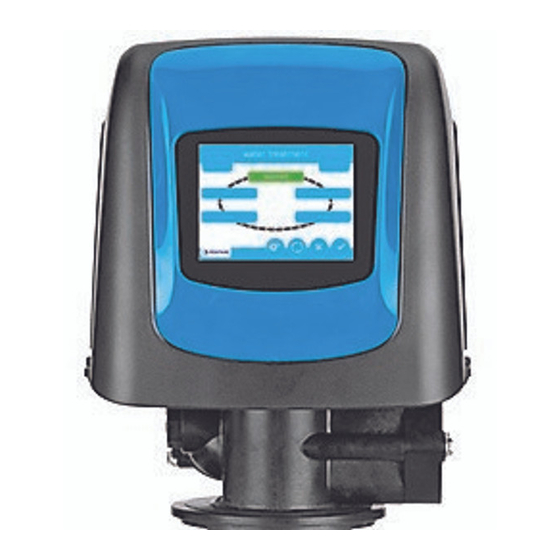
- Page 1 FLECK 5810 & 5812 XTR2 WATER SOFTENER OR FILTER CONTROL VALVE SERVICE MANUAL 5810 5812...
-
Page 2: Job Specification Sheet
TABLE OF CONTENTS IMPORTANT PLEASE READ: JOB SPECIFICATION SHEET 1. Meter Size: OPERATING PARAMETERS 2. System Type: 3. Cycle Settings: 4. Drain Line Flow Control:_____________________________ gpm 5. Brine Line Flow Control: ____________________________ gpm 6. Injector Size#: ________________________________________ Component CALIFORNIA PROPOSITION 65 WARNING This product contains chemicals known to the WARNING: State of California to cause cancer or birth... -
Page 3: Installation
INSTALLATION Water Pressure Electrical Facilities Existing Plumbing Location of System and Drain If grid plate is used, cut air check height just below CAUTION the grid plate. This is critical on 6", 7", 8" and 9" tanks. The brine refill water must come above the grid plate and make contact with the salt. - Page 4 TOUCHSCREEN CONTROL FEATURES Assistance Features of the XTR2 Touchscreen Control USB Connect Buttons and Symbols NOTE: Not all buttons appear on all screens. Regeneration Cycle Wheel Screen Navigation Arrows NOTE: Settings on previous screen are not saved unless is pressed. Settings Arrows NOTE: On metered units, the "Treatment"...
-
Page 5: Screen Features
TOUCHSCREEN CONTROL FEATURES • Day and Time continued Screen Features Regeneration Home Screen Next Scheduled Regeneration Regeneration Day and Time Current Cycle Step Return to Home Screen Regeneration Cycle Wheel Vacation Diagnostics Regeneration Assistance Settings at regen. time at regen. time Day and Time NOTE: If no button is pushed for five minutes, the screen will... -
Page 6: User Assistance
TOUCHSCREEN CONTROL FEATURES User Assistance continued Settings Assistance Settings Home NOTE: The Assistance screen is also displayed automatically Brightness Master Settings when the system reaches the programmed assistance interval. See TOUCHSCREEN CONTROL QUICK START. Master Settings day override regen time Improperly adjusting master settings may cause CAUTION the system to operate incorrectly. -
Page 7: Format Screen
TOUCHSCREEN CONTROL FEATURES continued 1201 • remote regen: MASTER SETTINGS PROGRAMMING Improperly adjusting master settings may cause CAUTION the system to operate incorrectly. Before entering master settings please contact your professional water dealer. NOTE: If a regeneration is scheduled to occur while in Master Settings, the scheduled regeneration will be cancelled. - Page 8 TOUCHSCREEN CONTROL QUICK START NOTE: Steps 3 and 4 are optional and are not required to start the system. All control settings may be changed after the unit is in service. NOTE: Press on any Quick Start screen to reset the screen back to its default settings.
- Page 9 TOUCHSCREEN CONTROL QUICK START continued Regeneration Next Scheduled Regeneration Day and Time Current Cycle Step Regeneration Cycle Wheel Vacation Diagnostics Regeneration Assistance Settings NOTE: Do not use granulated or rock salt. Day and Time Day and Time Year Month Day of Week Hour AM/PM/HR Minute...
- Page 10 INSTALLATION continued Typical Residential System Plumbing Bath Tub Lavatory Toilet Kitchen Outside Outside Faucet Faucet Hot Water Grounding Soft Water Outlet Strap Hard Water Bypass Drain Line Water Heater Brine Tank Over ow Drain (Optional) Laundry Tubs Pump Meter Softener Floor Drain FLECK...
-
Page 11: System Disinfection
START-UP INSTRUCTIONS/ SYSTEM DISINFECTION FLUSHING & CONDITIONING Disinfection of Water Softeners Sodium or Calcium Hypochlorite Application 5.25% Sodium Hypochlorite NOTE: Do not use granulated or rock salt. Calcium Hypochlorite FLECK... - Page 12 MASTER SETTINGS PROGRAMMING Valve Screen continued • language valve • units • hardness units NOTE: Degree hardness units are converted to ppm upon input. Degree inputs may be rounded up or down to the nearest ppm equivalent. USB Connection for Field Programming •...
- Page 13 MASTER SETTINGS PROGRAMMING • regen flow continued • downflow • downflow 2X backwash • custom upflow / downflow / filter • variable refill Filter Immediate Relay Output Screen relay Filter Delayed NOTE: If Filter Immediate or Filter Delayed are selected, Regenerant Flow selections are limited to Filter and Upflow Filter.
- Page 14 MASTER SETTINGS PROGRAMMING Remote Regen Screen continued Meter Screen remote regen meter • remote regen duration: • meter type • generic • plumbing leak detect Settings Review FLECK...
- Page 15 MASTER SETTINGS PROGRAMMING continued Non-Factory Settings Error Log Reset Reset 1201 Home NOTE: If a regeneration occurs while in the Diagnostic screen, the unit will return to the main screen. Parameter Description Diagnostics Diagnostics NOTE: Only Peak Flow and Totalizer can be changed - they can be reset to zero.
- Page 16 MASTER SETTINGS REFERENCE CHART Before entering Master Settings, please contact your local professional water dealer. CAUTION Screen Name Parameters Values Notes NOTE: Some items may not be shown depending on control configuration. The control will discard any changes and exit Master Settings if any button is not pressed for five minutes. FLECK...
-
Page 17: Master Reset
MASTER RESET If power fails during a regeneration cycle, the CAUTION valve will remain in its current position until power is restored. The valve system should include all required safety components to prevent overflows resulting from a power failure during regeneration. Remote Lockout factory non-factory... -
Page 18: Troubleshooting
TROUBLESHOOTING Problem Cause Correction Error Alerts NOTE: An Error Alert appears on the Home screen if an error condition is detected. Press the Error Alert button to view the error message. NOTE: Most error alerts are cleared at regeneration. If the error persists following a regeneration attempt the appropriate reset and recovery procedure below or contact technical support. - Page 19 5810 CONTROL VALVE ASSEMBLY Item No. Part No. Description NOTE: Above part numbers DO NOT include the following parts. Cover Bezel Distributor Adapter Bypass Assembly Connector Assembly Power Supply Flow Washer DLFC See 5810/5812 accessories page for options. 5812 CONTROL VALVE ASSEMBLY Item No.
- Page 20 5810 CONTROL VALVE ASSEMBLY Item No. Part No. Description NOTE: Install injector in hole "DF" and plug in hole "UF" for downflow units. In upflow units the injector plug and injector assembly are installed in reverse holes. In filter units, both injector holes are plugged with 61959.
- Page 21 5812 CONTROL VALVE ASSEMBLY Item No. Part No. Description **See NOTE below. NOTE: Install injector in hole "DF" and plug in hole "UF" for downflow units. In upflow units the plug and injector are installed in reverse holes. In filter units, both injector holes are plugged with 61959.
- Page 22 5810/5812 VALVE ACCESSORIES DLFC - 5810 ONLY Covers Bezels DLFC - 5812 ONLY Adapter Kits Bypasses Connector Assemblies Connector Elbow Power Supplies Washers FLECK...
- Page 23 5810/5812 VALVE ASSEMBLIES BLFC Injector Assemblies Injector Caps Powerheads Timers Meters Meter Cables FLECK...
-
Page 24: Safety Brine Valve
SAFETY BRINE VALVE 42112 Rev A Item No. Part No. Description FLECK... -
Page 25: Water Conditioner Flow Diagrams
WATER CONDITIONER FLOW DIAGRAMS 5810 Upflow FLECK... - Page 26 WATER CONDITIONER FLOW DIAGRAMS continued 5810 Downflow FLECK...
- Page 27 WATER CONDITIONER FLOW DIAGRAMS 5812 Upflow FLECK...
- Page 28 WATER CONDITIONER FLOW DIAGRAMS continued 5812 Downflow FLECK...
- Page 29 5810 DIMENSIONAL DRAWINGS 71.50 2.815 287.4 11.32 5.75 47.8 1.88 29.6 1.17 140.1 120.3 5.52 4.74 122.4 4.82 91.4 3.60 182.9 7.20 FLECK...
- Page 30 5812 DIMENSIONAL DRAWINGS 5812 2.5" BASE 71.50 2.815 12.0 171.2 6.74 5.51 65.4 2.57 29.6 1.17 91.4 140.08 120.3 3.60 5.515 4.74 182.9 7.20 5812 4" BASE 71.50 2.815 12.0 170.31 6.71 140.1 5.52 65.5 2.58 36.8 1.45 91.4 3.60 140.1 120.3 5.51...
-
Page 31: Wiring Diagram
WIRING DIAGRAM LOCK REMOTE LOCK START START TANK SENSOR OPTIONAL MOTOR PHOTO REMOTE SIGNAL START INTERRUPTER OPTIONAL HOME 1 SWITCH (N.O.) INTERLOCK FUTURE USE SWITCH (N.O.) MOTOR CLOSED CLOSED CONTACT CONTACT INITIATES SIGNAL PREVENTS REGENERATION FLOW REGENERATION IF ENABLED IF ENABLED CHLORINE GENERATOR (INTERNATIONAL... -
Page 32: Injector Flow Data
INJECTOR FLOW DATA TR18755 REV B FLECK... - Page 33 FLECK...
- Page 34 FLECK...
- Page 35 FLECK...
- Page 36 For a detailed list of where Pentair trademarks are registered, please visit waterpurification.pentair.com/brands. Pentair trademarks and logos are owned by Pentair plc or its affiliates. Third party registered and unregistered trademarks and logos are the property of their respective owners.
Need help?
Do you have a question about the FLECK 5812 XTR2 and is the answer not in the manual?
Questions and answers