Table of Contents
Advertisement
Quick Links
Download this manual
See also:
User Manual
Advertisement
Table of Contents

Subscribe to Our Youtube Channel
Related Manuals for Rohde & Schwarz RTP Series


Summary of Contents for Rohde & Schwarz RTP Series
-
Page 1: Getting Started
® R&S High-Performance Oscilloscope Getting Started (=Uñ^2) 1337994602... - Page 2 ® This manual describes the following R&S RTP models with firmware version 4.60 and higher: ● R&S ® RTP044 (1320.5007K04) ● R&S ® RTP064 (1320.5007K06) ● R&S ® RTP084 (1320.5007K08) ● R&S ® RTP134 (1320.5007K13) ● R&S ® RTP164 (1320.5007K16) ©...
-
Page 3: Table Of Contents
® Contents R&S Contents 1 Safety Information..............5 2 Preface..................7 2.1 Key Features..................7 2.2 Documentation Overview..............7 3 Preparing for Use..............11 3.1 Unpacking and Checking the Instrument......... 11 3.2 Positioning the Instrument..............12 3.3 Starting the Instrument..............14 3.4 Connecting External Devices............16 4 Instrument Tour.............. - Page 4 ® Contents R&S 5.11 Getting Information and Help............66 6 Setting Up the Instrument...........69 6.1 Performing a Self-alignment.............. 69 6.2 Setting the Display Language............70 7 Contacting Customer Support........... 71 Index..................72 Getting Started 1337.9946.02 ─ 05...
-
Page 5: Safety Information
® Safety Information R&S Safety Information The R&S RTP oscilloscope is designed for measurements on circuits that are only indirectly connected to the mains or not connected at all. It is not rated for any measurement category. The instrument is rated for pollution degree 2 - for indoor, dry location use where only non-conductive pollution occurs. - Page 6 ® Safety Information R&S Risk of instrument damage due to inappropriate operating conditions An unsuitable operating site or test setup can damage the instrument and connected devices. Before switching on the instrument, observe the infor- mation on appropriate operating conditions provided in the data sheet. In particular, ensure the following: ●...
-
Page 7: Preface
® Preface R&S Documentation Overview Preface Key Features The R&S RTP high-performance oscilloscopes combine superior signal integrity with fastest acquisition rate. It combines multiple instrument capabilities for time- correlated debugging in one box. Outstanding key features are: Real-time signal integrity ●... - Page 8 ® Preface R&S Documentation Overview 2.2.1 Manuals and Instrument Help You find the manuals on the product page at: www.rohde-schwarz.com/manual/rtp Getting started manual Introduces the R&S RTP and describes how to set up and start working with the instrument, and describes basic operations. A printed English version is included in the delivery.
- Page 9 ® Preface R&S Documentation Overview – R&S RT-ZF2 Ethernet Compliance Test Fixture Set – R&S RT-ZF3 Frequency Converter Board (100BASE-T1) – R&S RT-ZF4 10BASE-Te Test Fixture – R&S RT-ZF5 Ethernet Probing Fixture – R&S RT-ZF6 Frequency Converter Board (1000BASE-T1) – R&S RT-ZF7 Automotive Ethernet T&D Fixture –...
- Page 10 ® Preface R&S Documentation Overview See www.rohde-schwarz.com/firmware/rtp. 2.2.4 Application notes, Application cards, Videos These documents deal with special applications or background information on particular topics. www.rohde-schwarz.com/application/rtp Oscilloscopes Application Vid- eos - Media Center Getting Started 1337.9946.02 ─ 05...
-
Page 11: Preparing For Use
® Preparing for Use R&S Unpacking and Checking the Instrument Preparing for Use This section describes the basic steps to be taken when setting up the R&S RTP for the first time. Observe the information on appropriate operating conditions provided in the data sheet and the general information given in "Risk of instrument damage due to inappropriate operating conditions"... -
Page 12: Positioning The Instrument
® Preparing for Use R&S Positioning the Instrument Positioning the Instrument The instrument is designed for use under laboratory conditions. It can be used in standalone operation on a bench top or can be installed in a rack. 3.2.1 Bench Top Operation For standalone operation, place the instrument on a horizontal bench with even, flat surface. - Page 13 ® Preparing for Use R&S Positioning the Instrument Risk of injury when stacking instruments A stack of instruments can tilt over and cause injury if not stacked correctly. Furthermore, the instruments at the bottom of the stack can be damaged due to the load imposed by the instruments on top.
-
Page 14: Starting The Instrument
® Preparing for Use R&S Starting the Instrument Risk of instrument damage due to insufficient airflow in a rack If you mount several instruments in a rack, you need an efficient ventilation concept to ensure that the instruments do not overheat. Insufficient airflow for a longer period can disturb the operation and even cause damage. - Page 15 ® Preparing for Use R&S Starting the Instrument Before you start measurements, be sure to comply with the warm-up phase specified in the data sheet. If you leave the main power switch on, the instrument is in standby mode. To dis- connect from power supply, power off the instrument.
-
Page 16: Connecting External Devices
® Preparing for Use R&S Connecting External Devices To shut down the instrument ► Press the [Power] key on the front panel. All current settings are saved, and the software shuts down. The [Power] key turns orange. The standby power supplies only the power switch circuits. Now it is safe to power off the instrument. - Page 17 ® Preparing for Use R&S Connecting External Devices The following USB devices can be useful, for example: ● USB flash drives to save screenshots and measurement results, and for easy installation of firmware applications ● Keyboard and/or mouse to simplify the operation and the entry of data, com- ments, filenames, etc.
- Page 18 ® Preparing for Use R&S Connecting External Devices To configure the keyboard properties: 1. Tap the "Find" icon (magnifier) on the Windows taskbar. 2. Type keybord. 3. Select "Edit language and keyboard options". Connecting a mouse The mouse is detected automatically when it is connected. To configure the mouse properties: 1.
- Page 19 ® Preparing for Use R&S Connecting External Devices After connecting an additional monitor or projector to the instrument, configure it for usage. The relevant settings are Windows settings but you can configure the displays directly in the instrument setup. 1. Check the input type of the monitor or projector. Make sure to select the cor- rect cable.
-
Page 20: Instrument Tour
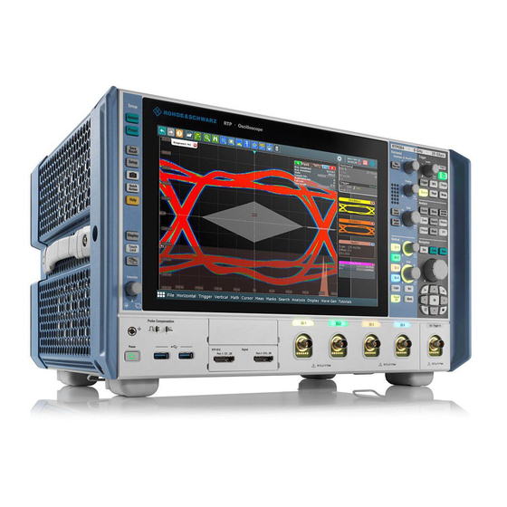
® Instrument Tour R&S Front Panel Instrument Tour This chapter describes the front and rear panels of the instrument including all function keys and connectors, and also the touchscreen with its control elements. Front Panel Figure 4-1 shows the front panel of the R&S RTP. The function keys are grouped in functional blocks to the left and the right of the touchscreen. - Page 21 ® Instrument Tour R&S Front Panel 5 = Analysis keys 6 = Navigation controls 7 = External trigger input 8 = Vertical controls 9 = Input channels 10 = Two option slots for R&S RTP-B1 (MSO) or R&S RTP-B1E (for R&S RT-ZVC) , R&S RTP- B6 (waveform generator), R&S RTP-B7 (pulse source) 11 = USB connectors 12 = Connectors for probe compensation and grounding...
- Page 22 ® Instrument Tour R&S Front Panel Probe Compensation Probe compensation terminal to support adjustment of passive probes to the oscilloscope channel. Protective earth conductor for grounding the instrument. Square wave signal for probe compensation, 1 kHz and 1 V Ground connector for probes. Two USB type A connectors that comply with standard USB 3.0.
-
Page 23: Rear Panel
® Instrument Tour R&S Rear Panel Pulse source option R&S RTP-B7 The pulse source outputs a symmetrical differential pulse signal. For detailed specifications, refer to the data sheet. The option can be installed in one of option slots at the front panel. The module has four connectors. - Page 24 ® Instrument Tour R&S Rear Panel 1 = AC power supply connector and main power switch 2 = USB device connector, type B 3 = USB connectors, type A 4 = LAN connector 5 = DVI-D connector for external monitor 6 = DisplayPort connector 7 = GPIB connector 8 = Exchangeable solid state disk (SSD, option R&S RTP-B18)
- Page 25 ® Instrument Tour R&S Rear Panel DisplayPort DisplayPort connector for an external monitor or projector. It supports DisplayPort version 1.1a. DVI-D Digital connector for an external monitor or projector. The monitor shows the com- plete content of the instrument's screen. GBIP Connector with GBIP interface.
-
Page 26: Keys And Controls
® Instrument Tour R&S Keys and Controls DDI 40G Optional digital data interface for input and output of digital data. Option slot Slot to install one of the options R&S RTP-B1 (MSO) or R&S RTP-B1E (for R&S RT-ZVC) if both slots at the front panel are used for other options. To install the option, the R&S RTP-B21 slot adapter is required. - Page 27 ® Instrument Tour R&S Keys and Controls [Save Recall] Opens and closes the "File" dialog box, where you can: ● Save instrument settings (user settings) ● Load instrument settings which were saved before ● Save waveform data and measurement results ●...
-
Page 28: Horizontal Controls
® Instrument Tour R&S Keys and Controls [Intensity] Adjusts the intensity of the waveforms on the screen, or the background transpar- ency of dialog boxes, or the transparency of result boxes. If a dialog box is open, turning the knob changes the transparency of dialog boxes. If a result box is open, the transparency of result boxes is changed. - Page 29 ® Instrument Tour R&S Keys and Controls [Acquisition] Opens and closes the "Acquisition" tab in the "Horizontal" dialog box, where you can define the acquisition processing (acquisition mode and waveform arith- metic). [Resolution / Record Length] The rotary knob changes the resolution or the record length. Press the knob to toggle the setting.
-
Page 30: Vertical Controls
® Instrument Tour R&S Keys and Controls 4.3.4 Vertical Controls The keys and knobs in the Vertical functional block select a signal and adjust the vertical scale and position of the selected signal. [Ch <n>] Turns on, selects, and configures a channel. If the channel is active, the key lights up in the corresponding channel color . -
Page 31: Trigger Controls
® Instrument Tour R&S Keys and Controls [Math] Opens the "Math" dialog box, where you can configure the calculation of mathe- matical waveforms using various mathematic operations on other waveforms. Press the key repeatedly to switch the math waveform. If a math waveform is selected, the vertical rotary knobs are illuminated in brown (default color), the brightness of the color depends on the selected waveform. - Page 32 ® Instrument Tour R&S Keys and Controls [Trigger] Opens and closes the "Trigger" dialog box, where you can: ● Select a trigger type and configure it. ● Set general trigger parameters and control the acquisition run. ● Qualify the trigger event with logic patterns. ●...
- Page 33 ® Instrument Tour R&S Keys and Controls [Mode] Toggles the trigger mode between Auto and Normal. The current setting is shown on the trigger label. [Run Stop] Starts and stops the continuous acquisition. A green light indicates a running acquisition. A red light shows that acquisition is stopped. [Single] Starts a defined number of acquisitions.
- Page 34 ® Instrument Tour R&S Keys and Controls ● Define style and labels of the cursors ● Connect the cursor to the waveform and couple the cursors [Meas] Starts the default automatic measurement for the active waveform and opens the "Measurement" result box. If you press the [Meas] key while a measurement is enabled, the "Measurements"...
- Page 35 ® Instrument Tour R&S Keys and Controls You can: ● Configure masks and masks segments ● Define mask test parameters ● Configure actions triggered by mask violation ● Configure the mask display [History] The sample memory contains several stored acquisitions before the current one, which is shown in the display.
- Page 36 ® Instrument Tour R&S Keys and Controls Navigation rotary knob The navigation knob has various functions: ● In numeric entry fields: turn to increase or decrease the value. ● In tables: press to activate the edit mode, turn clockwise to increase the value or turn counterclockwise to decrease it, and press to enter the value and move to the next cell.
- Page 37 ® Instrument Tour R&S Keys and Controls ● In dialog boxes with only horizontal tabs, the key switches the horizontal tabs. ● In dialog boxes with horizontal and vertical tabs, the key switches the tabthat has the focus. ● In a table or diagram, the key moves the focus in the same way as the [▶] key. Up arrow [▲], Down arrow [▼] The up and down arrow keys have the following effects: ●...
-
Page 38: Operating The Instrument
® Operating the Instrument R&S Means of Manual Interaction Operating the Instrument There are three ways to operate the R&S RTP. Manual operation Use the touchscreen, keys and rotary knobs, or an optional mouse and/or key- board. The principles of manual operation are explained in this section. Remote control Create programs to automatize repeating settings, tests, and measurements. -
Page 39: Touchscreen Display
® Operating the Instrument R&S Touchscreen Display Using the touchscreen is the direct interaction way. Use your finger to place waveforms on the screen, mark areas for zoom and histograms, set parame- ters in dialog boxes, enter data, and much more. The control elements and actions on the screen are based on common concepts, and you will easily become familiar with the user interface. - Page 40 ® Operating the Instrument R&S Touchscreen Display Figure 5-1: Display information 1 = Diagram 2 = Grid 3 = Sidebar with horizontal and trigger label (3a), signal icon with waveform settings (3b) and signal icon with minimized live waveform (3c) 4 = Trigger level 5 = Trigger position 6 = Reference point (distance from trigger position to reference point = horizontal position)
- Page 41 ® Operating the Instrument R&S Touchscreen Display To arrange the diagrams on the screen, the Rohde & Schwarz SmartGrid function helps you to find the target place simply and quickly. For details, see Chapter 5.5, "Rohde & Schwarz SmartGrid", on page 49. You can also adjust the diagram size by dragging the diagram border.
- Page 42 ® Operating the Instrument R&S Touchscreen Display Figure 5-1, the signal icons Ch1Wfm1 and Ch2Wfm1 show the main settings, and the waveforms are displayed in diagrams. All other waveforms are minimized and shown in the signal icon. Figure 5-3: Signal label on the sidebar 1 = Vertical scale 2 = Vertical position 3 = Coupling and Termination...
- Page 43 ® Operating the Instrument R&S Touchscreen Display Zoom diagram and zoom area (7, 8) Zoomed waveforms are shown in separate zoom diagrams, in addition to the waveform diagrams. On the original waveform diagram, a rectangle indicates the zoomed section of the waveform - this is the zoom area. You can modify the zoom area by dragging the rectangle as a whole, and by dragging its edges.
- Page 44 ® Operating the Instrument R&S Touchscreen Display Figure 5-4: Control elements on the touchscreen 1 = Toolbar 2 = Sidebar, see "Sidebar (3)" on page 41 3 = Menu bar 4 = Dialog box 5 = Tab in a dialog box 6 = Result box 7 = Input box Toolbar (1)
-
Page 45: App Cockpit
® Operating the Instrument R&S App Cockpit Result box (6) If you perform manual or automatic measurements, mask testing, or a search, the result box shows the results of the action. Similar to waveform diagrams, you can minimize the result box to a result icon on the sidebar, and display results in a separate diagram on the screen. -
Page 46: Working With Waveforms
® Operating the Instrument R&S Working with Waveforms Working with Waveforms The R&S RTP can create and display several types of waveforms: ● Channel waveforms: Up to three waveforms per input channel can be shown. For a four-channel instrument, 12 channel waveforms are available. ●... - Page 47 ® Operating the Instrument R&S Working with Waveforms Waveform handling The R&S RTP can show and analyze many waveforms. To handle this multitude while keeping track of it, the R&S RTP provides intelligent support: ● The color system helps to distinguish the waveforms. The color of the vertical rotary knobs indicates the signal that is focused (selected).
- Page 48 ® Operating the Instrument R&S Working with Waveforms To switch a waveform on A channel waveform is activated as soon as you connect the probe. You can switch it on and off according to your needs. ► Choose one of the following ways: ●...
-
Page 49: Rohde & Schwarz Smartgrid
® Operating the Instrument R&S Rohde & Schwarz SmartGrid ● To switch off a minimized waveform, tap the "Close" icon in the upper right corner of the minimized signal view. ● Disable "Show channel" in the "Vertical" > "Channels" tab. ●... -
Page 50: Toolbar
® Operating the Instrument R&S Toolbar The Rohde & Schwarz SmartGrid appears and a blue area shows where the waveform will be placed. 2. Drop the waveform in the target area. The waveform appears in an existing or in a new diagram, and it is selected for further actions. - Page 51 ® Operating the Instrument R&S Toolbar 5.6.1 Using the Toolbar Using the toolbar is easy and straightforward. Some of the toolbar functions are one-click actions. These actions are performed immediately when you tap the icon. Other toolbar functions are analyzing functions. These actions are interactive actions.
- Page 52 ® Operating the Instrument R&S Toolbar 5.6.2 Configuring the Toolbar You can configure the contents of the toolbar so that only the required functions are displayed. Furthermore, date and time can be hidden. The toolbar configura- tion is part of the user preferences. It is retained when you switch off and on the instrument, and you can save it in the user preferences and user-defined preset.
- Page 53 ® Operating the Instrument R&S Toolbar One-click actions Interactive actions Undo Zoom Redo Search Show Help Cursor Graphical Recall (load saveset) Masktest Save Settings Histogram Save Screenshot Measurement Create Report Quick meas Clear all Autoset and Preset Delete Run / Stop and Run Single Label Find Trigger Level Update Ref Waveform...
- Page 54 ® Operating the Instrument R&S Toolbar One-click actions Interactive actions Spectrogram (option R&S RTP-K37) Zone trigger (option R&S RTP-K19) You can configure the content of the toolbar and hide the date/time display, Chapter 5.6.2, "Configuring the Toolbar", on page 52. The following list describes at first the default toolbar functions and then the addi- tional functions.
- Page 55 ® Operating the Instrument R&S Toolbar Tap the icon and drag a rectangle on the diagram to mark the zoom area. An additional zoom diagram appears. You can use the tool also repeatedly on the zoom diagram to get a more detailed view. Touch and hold the zoom area to open the "Zoom"...
- Page 56 ® Operating the Instrument R&S Toolbar Tap the diagram where you want to set the cursors, or draw a rectangle in the dia- gram to position the cursor lines. The resulting cursor lines measure the selected waveform. The results appear in the "Cursor Results" box. You can adjust the cur- sor source, type and position in the result box.
- Page 57 ® Operating the Instrument R&S Toolbar Transforms a waveform to the frequency spectrum by fast Fourier trans- form (FFT). The FFT trace is shown in a new diagram. Tap the icon and adjust the settings in the sidebar. Tap diagram with the wave- form to be transformed.
- Page 58 ® Operating the Instrument R&S Toolbar Run / Stop and Run Single Starts and stops the continuous acquisition, or starts a defined number of acquisition cycles. The icons have the same functionality as the corre- sponding keys on the front panel. They are useful when you control the instru- ment remotely.
-
Page 59: Displaying Results
® Operating the Instrument R&S Displaying Results Tap the icon. Select the source in the sidebar, or tap diagram with the waveform to be transformed. The diagrams are created from the selected waveform. Zone trigger (option R&S RTP-K19) Defines a zone trigger, which combines the trigger condition with the inter- section or non-intersection of one or more zones or masks. - Page 60 ® Operating the Instrument R&S Displaying Results 1 = Floating result box 2 = Table in a tab on the left or right 3 = Table in a tab above or below 4 = New tab To open the corresponding setup dialog box 1.
-
Page 61: Using Dialog Boxes
® Operating the Instrument R&S Using Dialog Boxes To adjust the font size in result boxes 1. Press the [Setup] key. 2. Select the "Screen" tab. 3. Set the "Result dialog font size". Using Dialog Boxes All functionality is provided in dialog boxes as known from computer programs. You can control the instrument intuitively with the touchscreen. - Page 62 ® Operating the Instrument R&S Using Dialog Boxes ● Tap the horizontal or trigger label to open the "Horizontal" or "Trigger" dia- log box, respectively. To minimize a dialog box If you want to change only one setting during analysis, and you need to change it often, you can display a small box that only contains the required setting.
-
Page 63: Entering Data
® Operating the Instrument R&S Entering Data c) Press the [▲] and [▼] keys to navigate to the required option in the list. d) Press the [☑] key to select the marked option. Entering Data Most important parameters have their own rotary knobs on the front panel. When you turn a knob, the input box appears the lower right corner of the screen, show- ing the parameter name and current value. - Page 64 ® Operating the Instrument R&S Entering Data 2. Enter the numeric value using the following methods: ● To use the default value, tap "Reset" (if available). ● To use the minimum or maximum value, tap "Min" or "Max", respectively. ● To increase the displayed value in fixed steps, tap "Inc". To decrease the value in fixed steps, tap "Dec".
-
Page 65: Messages
® Operating the Instrument R&S Messages 2. Enter the text as you would on a normal keyboard. ● To enter a series of capital characters, tap "Caps". To enter one capital character, tap "Shift". ● To use the currently defined value, tap "Cur". This is the value that was used before the keyboard was displayed. -
Page 66: Getting Information And Help
® Operating the Instrument R&S Getting Information and Help ► To open and close the message box, tap the "Info" button. If no messages are available, the "Info" button is hidden. Important messages are indicated by a red "Info" button. These messages cannot be deleted, they remain until the problem is solved. - Page 67 ® Operating the Instrument R&S Getting Information and Help Note: The tooltip icon disables automatically when you tap a parameter. To show another tooltip, tap the tooltip icon again. To open general help ► Press the yellow [Help] button on the left side of the screen. If a dialog box is open, the help topic for the current tab is shown.
- Page 68 ® Operating the Instrument R&S Getting Information and Help The entries containing these characters are displayed. 4. Double-tap the suitable index entry. The "View" tab with the corresponding help topic is displayed. To search topics for a text string 1. Switch to the "Search" tab. 2.
-
Page 69: Setting Up The Instrument
® Setting Up the Instrument R&S Performing a Self-alignment Setting Up the Instrument Basic setup procedures for the instrument are the following: ● Performing a Self-alignment................69 ● Setting the Display Language................. 70 Performing a Self-alignment The self-alignment aligns the data from several input channels vertically and hori- zontally to synchronize the timebases, amplitudes and positions. -
Page 70: Setting The Display Language
® Setting Up the Instrument R&S Setting the Display Language Setting the Display Language You can change the language in which the dialog boxes, result boxes and other screen information is displayed. A reboot of the instrument is not necessary. 1. -
Page 71: Contacting Customer Support
® Contacting Customer Support R&S Contacting Customer Support Technical support – where and when you need it For quick, expert help with any Rohde & Schwarz equipment, contact one of our Customer Support Centers. A team of highly qualified engineers provides tele- phone support and works with you to find a solution to your query on any aspect of the operation, programming or applications of Rohde &... -
Page 72: Index
® Index R&S Index Display elements Diagram ..........39 Acquisition Input box ..........43 Key ............29 Menu bar ..........43 Single, multiple ........33 Result box ........... 43 Start ............ 33 Sidebar ..........39 Stop ............ 33 Toolbar ..........43 Active waveform ........47 DisplayPort ........ - Page 73 ® Index R&S Position ..........29 Numeric data entry ........63 Reference point ........29 OCXO ............25 Input box ..........43 Offset Intensity key ..........28 Channel ..........31 Intensity of display elements ....28 OK key .............36 On/Off key ..........26 Open source acknowledgment ....
- Page 74 ® Index R&S Reference waveforms ....... 30, 46 Switch off Release notes ........... 9 Waveform ..........48 Remote control ........38 Switch on Find command using help ....66 Waveform ..........48 Remote Desktop ........38 Remote operation ........38 Res Rec Len key ........28 Temperature Resolution Changes ..........
- Page 75 ® Index R&S Undo Key ............36 Toolbar ..........54 Unlock touchscreen ......... 27 Cable ..........22 Connecting ..........16 Connector ........... 22 Device ..........24 USB flash drive ........17 User manual ..........8 Vertical Controls ..........30 Position / Offset ........31 VNC ............
Need help?
Do you have a question about the RTP Series and is the answer not in the manual?
Questions and answers