Table of Contents
Advertisement
Quick Links
Advertisement
Table of Contents

Related Manuals for Neousys Technology Nuvo-5501 Series


Summary of Contents for Neousys Technology Nuvo-5501 Series
- Page 1 Neousys Technology Inc. Nuvo-5501 Series User Manual Revision 1.1...
-
Page 2: Table Of Contents
1.1.1 Nuvo-5501 ......................11 1.1.2 Nuvo-5501-DIO ....................13 Dimension ......................... 15 1.2.1 Top View of Nuvo-5501 Series ................15 1.2.2 Front View of Nuvo-5501 Series ............... 15 1.2.3 Back View of Nuvo-5501 Series ................ 16 1.2.4 Side View of Nuvo-5501 Series ................ 16 System Overview Nuvo-5501 Packing List ................... - Page 3 Table of Contents 3.8.1 Installing Wall-Mounting Bracket ............... 59 3.8.2 Installing DIN-Rail Mounting Kit (Optional) ............61 BIOS Settings COM1 & COM2 Configuration .................. 63 Power On After Power Failure Option ..............64 Power & Performance (CPU SKU Power Configuration) ........65 Wake on LAN Option ....................
-
Page 4: Legal Information
For questions in regards to hardware/ software compatibility, customers should contact Neousys Technology Inc. sales representative or technical support. To the extent permitted by applicable laws, Neousys Technology Inc. shall NOT be responsible for any interoperability or compatibility issues that may arise when (1) products, software, or options not certified and supported;... -
Page 5: Contact Information
3384 Commercial Avenue, Northbrook, IL 60062, USA (Illinois, USA) Tel: +1-847-656-3298 Email, Website China Neousys Technology China Co., Ltd. Room 429 /431, Building 32, Guiping Road 680, Shanghai, 200233, China Tel: +86-2161155366 Email, Website Declaration of Conformity This equipment has been tested and found to comply with the limits for a Class A digital device, pursuant to part 15 of the FCC Rules. -
Page 6: Copyright Notice
This manual is intended to be used as an informative guide only and is subject to change without prior notice. It does not represent commitment from Neousys Technology Inc. Neousys Technology Inc. shall not be liable for any direct, indirect, special, incidental, or consequential damages arising from the use of the product or documentation, nor for any infringement on third party rights. -
Page 7: Safety Precautions
Safety Precautions Safety Precautions Read these instructions carefully before you install, operate, or transport the system. Install the system or DIN rail associated with, at a sturdy location. Install the power socket outlet near the system where it is easily accessible. ... -
Page 8: Service And Maintenance
Service and Maintenance/ ESD Precautions Service and Maintenance ONLY qualified personnel should service the system Shutdown the system, disconnect the power cord and all other connections before servicing the system When replacing/ installing additional components (expansion card, memory module, etc.), insert them as gently as possible while assuring proper connector engagement ESD Precautions... -
Page 9: About This Manual
About This Manual About This Manual This guide introduces Neousys Nuvo-5501 system. It is a compact fanless embedded controller with Intel® 6th-Gen Core i7/ i5/ i3 processor. The guide also demonstrates the system’s basic installation procedures. Revision History Version Date Description Apr. -
Page 10: Introduction
Nuvo-5501 Series Introduction Nuvo-5501 series features compact fanless embedded controllers for the cost and ® space conscious. Based on Intel Skylake platform, it is designed to provide cutting-edge performance and reliable operation in extreme environment. Its LGA 1151 socket offers users the flexibility to select a 35W CPU from 6 -Gen Intel®... -
Page 11: Product Specifications
Nuvo-5501 Series Product Specifications 1.1.1 Nuvo-5501 System Core Supports following CPUs Intel® Core i7-6700TE (8M Cache, 2.4/ 3.4 GHz, 35W TDP) Intel® Core i5-6500TE (6M Cache, 2.3/ 3.3 GHz, 35W TDP) Processor Intel® Core i3-6100TE (4M Cache, 2.7 GHz, 35W TDP) Intel®... - Page 12 CE/FCC Class A, according to EN 55032 & EN 55024 * The 100% CPU loading is applied using Passmark® BurnInTest 8.1. For detail testing criteria, please contact Neousys Technology. ** For sub-zero operating temperature, a wide temperature HDD drive or Solid State Disk...
-
Page 13: Nuvo-5501-Dio
Nuvo-5501 Series 1.1.2 Nuvo-5501-DIO System Core Supports following CPUs Intel® Core i7-6700TE (8M Cache, 2.4/ 3.4 GHz, 35W TDP) Intel® Core i5-6500TE (6M Cache, 2.3/ 3.3 GHz, 35W TDP) Processor Intel® Core i3-6100TE (4M Cache, 2.7 GHz, 35W TDP) Intel® Pentium® G4400TE (3M Cache, 2.4 GHz, 35W TDP) Intel®... - Page 14 CE/FCC Class A, according to EN 55032 & EN 55024 * The 100% CPU loading is applied using Passmark® BurnInTest 8.1. For detail testing criteria, please contact Neousys Technology. ** For sub-zero operating temperature, a wide temperature HDD drive or Solid State Disk...
-
Page 15: Dimension
Nuvo-5501 Series Dimension 1.2.1 Top View of Nuvo-5501 Series NOTE All measurements are in millimeters (mm). 1.2.2 Front View of Nuvo-5501 Series NOTE All measurements are in millimeters (mm). -
Page 16: Back View Of Nuvo-5501 Series
Nuvo-5501 Series 1.2.3 Back View of Nuvo-5501 Series DIO port is applicable to the highlighted area in blue for Nuvo-5501-DIO system. 1.2.4 Side View of Nuvo-5501 Series NOTE All measurements are in millimeters (mm). -
Page 17: System Overview
Upon receiving and unpacking your Nuvo-5501, please check immediately if the package contains all the items listed in the following table. If any item(s) are missing or damaged, please contact your local dealer or Neousys Technology. Nuvo-5501 Packing List System... -
Page 18: Front Panel I/O
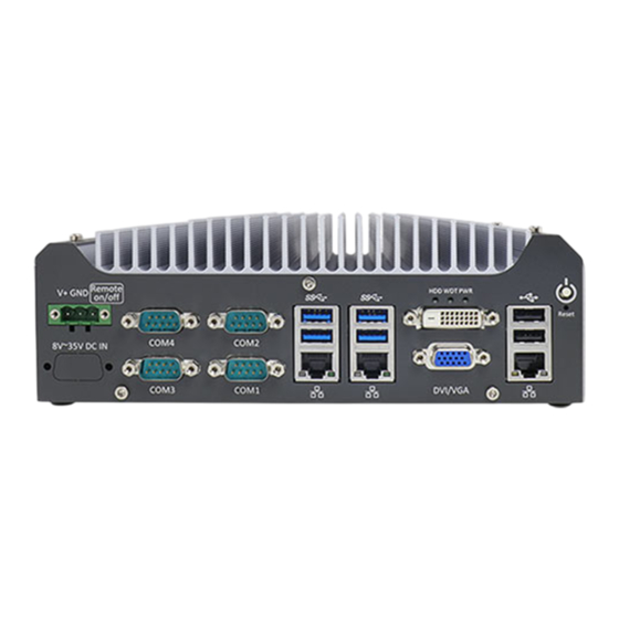
Nuvo-5501 Series Front Panel I/O The Nuvo-5501 I/O panel features three gigabit Ethernet ports, four USB3.0 ports, two USB2.0 ports, one VGA connector, one DVI-D connector and four serial ports. Item Description Power button Use this button to turn on or shutdown the system. -
Page 19: Power Button
Nuvo-5501 Series 2.2.1 Power Button The power button is a non-latched switch for ATX mode on/off operation. Press to turn on the system, PWR LED should light up and to turn off, you can either issue a shutdown command in the OS, or just press the power button. In case of system halts, you can press and hold the power button for 5 seconds to force-shutdown the system. -
Page 20: Usb 2.0 Ports
2.2.3 USB 2.0 Ports In addition to USB 3.0, Nuvo-5501 Series provides two USB 2.0 ports on the front panel. They are implemented by native xHCI (eXtensible Host Controller Interface) controller in H110 chipset and are compatible with USB 2.0, USB 1.1 and USB 1.0 devices. -
Page 21: Gigabit Ethernet
Nuvo-5501 Series 2.2.4 Gigabit Ethernet The system offers 3 GbE ports on its I/O panel. The GbE ports are marked in blue/ ® ® and are implemented with Intel I219-LM/ Intel I210-IT controllers, respectively. Each port has one dedicated PCI Express link for maximum performance. When an... -
Page 22: Vga Port
Nuvo-5501 series has dual display outputs on its front panel for connecting different displays according to your system configuration. VGA connector is the most popular way for connecting a display. The VGA output on Nuvo-5501 series supports up to 1920 x 1200 resolution. To support multiple display outputs and achieve best DVI output resolution in Windows, you need to install corresponding graphics driver. -
Page 23: Dvi-D Port
Nuvo-5501 Series 2.2.6 DVI-D Port The system has one DVI-D connector on its I/O panel to support independent display output. DVI transmits graphics data in digital format and therefore can deliver better image quality at high resolutions. The DVI connector can output DVI or other digital signals via an adapter or dedicated cable up to 1920 x 1200 resolution. -
Page 24: System Status Led Indicators
Nuvo-5501 Series 2.2.7 System Status LED Indicators There are three LED indicators on the I/O panel: PWR, WDT and HDD. The descriptions of these three LED are listed in the following table. Indicator Color Description Green Power indicator, lighted-up when system is on. -
Page 25: Com Port
Nuvo-5501 Series 2.2.9 COM Port The system provides four COM ports for communicating with external devices. These COM ports are implemented using industrial-grade ITE8786 Super IO chip (-40 to 85°C) and provide up to 115200 bps baud rate. COM1 and COM2 are software-configurable RS-232/422/485 ports. COM3 and COM4 are standard 9-wire RS-232 ports. -
Page 26: 2.2.10 3-Pin Terminal Block For Dc Input
Nuvo-5501 Series 2.2.10 3-Pin Terminal Block for DC Input The system allows DC power input from 8 to 35V via a 3-pin pluggable terminal block, which is ideal for field usage where DC power is provided. The screw clamping mechanism of the terminal block offers utmost reliability when wiring DC power. -
Page 27: Rear Panel Dio Port (Nuvo-5501-Dio Only)
Nuvo-5501 Series Rear Panel DIO Port (Nuvo-5501-DIO Only) The digital input (DI) and digital output (DO) function provides eight isolated DI and eight isolated DO on the back panel of Nuvo-5501 via DB25 female connector. Pin Definition Pin # Signal... -
Page 28: Internal I/O Functions
Nuvo-5501 Series Internal I/O Functions In addition to I/O connectors on the front panel, the system also provides internal on-board connectors, such as remote on/off control, LED status output, internal USB 2.0 ports and etc. In this section, we’ll illustrate these internal I/O functions. - Page 29 Nuvo-5501 Series Pin# Definition Description WDT_LED- [Output] Watchdog timer indicator, flashing when watchdog timer is started. WDT_LED+ Un-used pin HDD- [Output] Hard drive indicator, flashing when SATA hard drive is active. HDD+ Power_LED- [Output]System power indicator, on if system is turned on, off if system is turned off.
-
Page 30: Single Dram So-Dimm Slot
Nuvo-5501 Series 2.4.2 Single DRAM SO-DIMM Slot 2.4.3 mSATA Slot Nuvo-5501 provides an mSATA port to accommodate mSATA flash disk module. mSATA is a solid-state disk with all the advantages of solid state disk technology such as lower power consumption and is extremely reliable for harsh environments... - Page 31 Nuvo-5501 Series mSATA Socket Definition Pin # Signal (mSATA) Pin # Signal (mSATA) +3.3Vaux +1.5V Mechanical key PERST# SATA Rxp +3.3Vaux SATA Rxn +1.5V SATA Txn SATA Txp USB D- USB D+ +3.3Vaux +3.3Vaux +1.5V +3.3Vaux...
-
Page 32: Mini-Pcie Slot
Nuvo-5501 Series 2.4.4 mini-PCIe Slot Nuvo-5501 series provides a mini-PCIe socket compliant with mini-PCIe specification rev. 1.2. There are plenty of off-the-shelf mini-PCIe modules with versatile capabilities. By installing a mini-PCIe module, your system can have expanded features such as WIFI, GPS, CAN bus, analog frame grabber, etc. - Page 33 Nuvo-5501 Series mini-PCIe slot definition Pin # Signal Pin # Signal WAKE# +3.3Vaux COEX1 COEX2 +1.5V CLKREQ# UIM PWR UIM DATA REFCLK- UIM CLK REFCLK+ UIM RESET UIM VPP Mechanical Key Reserved* (UIM C8) Reserved* (UIM C4) W DISABLE# PERST# PERn0 +3.3Vaux...
-
Page 34: 2242 And Sim Card Slot
Nuvo-5501 Series 2.4.5 M.2 2242 and SIM Card Slot The system has a M.2 2242 (indicated in blue) slot that works in cooperation with a SIM slot (indicated in red). By installing a M.2 module, you can install a 3G/ 4G module with a SIM card for internet access via your service provider’s 3G/ 4G... - Page 35 Nuvo-5501 Series M.2 Slot Pin Definition Pin # Signal Pin # Signal P3V3 P3V3 USB D+ USB D- UIM RST UIM CLK UIM DATA UIM PWR PLTRST PLTRST P3V3 P3V3 P3V3...
-
Page 36: Sata Port
2.4.6 SATA Port Nuvo-5501 series provides two SATA ports which support Gen3, 6 Gb/s SATA signals. Each SATA port is composed of a 7-pin SATA connector (indicated in blue) and a 4-pin power connector (indicated in red). A dedicated cable is shipped with the... -
Page 37: Internal Usb Port
Nuvo-5501 Series 2.4.7 Internal USB Port Nuvo-5501 series provides one additional USB port internally on the PCBA. It supports standard USB 2.0 signals. You can utilize this USB port to connect a USB protection dongle inside the chassis of Nuvo-5501 controller. -
Page 38: System Installation
Nuvo-5501 Series System Installation Before disassembling the system enclosure and installing components and modules, please make sure you have done the following: It is recommended that only qualified service personnel should install and service this product to avoid injury or damage to the system. - Page 39 Nuvo-5501 Series Unscrew the four(4) screws shown on top of the enclosure. Unscrew the three (3) screws (indicated in blue) to remove the rear panel. Unscrew the four (4) screws at the bottom of the system holding the four rubber...
- Page 40 Nuvo-5501 Series Gently lift and remove the bottom panel. For Nuvo-5501-DIO, you must disconnect the DIO connection cable to the motherboard before you can remove the enclosure completely.
-
Page 41: Cpu Installation
Nuvo-5501 Series CPU Installation DO NOT remove the CPU from its container / tray before it is ready to be installed. With the enclosure panels removed, to access the CPU socket, please do the following: i. If you are installing a CPU for the first time, remove the four (4) screws indicated in blue. - Page 42 Nuvo-5501 Series motherboard. DO NOT touch the pins in the LGA socket! Remove the CPU from its container/ tray. Match the two notches on the side to the protrusions in the socket, gently lower the CPU into the socket. Locate the CPU retention bracket from the accessory box. Place the retention...
- Page 43 Nuvo-5501 Series Turn the motherboard around and secure the bracket by tightening two M3 P-head screws. Hold CPU bracket firmly and turn Secure two M3 P-head screws the motherboard around Remove all thermal pads’ protective films on the heatsink.
- Page 44 Nuvo-5501 Series With the five motherboard standoffs aligned, gently lower the motherboard onto the heatsink. Secure the four (4) M3 P-head motherboard screws (indicated in blue) and from the accessory box, five (5) M3 spring screws (indicated in red). Gradually tighten the five screws in the following order for even pressure.
-
Page 45: Ddr4 So-Dimm Installation
Nuvo-5501 Series 11. If you need to install other components, please refer to respective sections. DDR4 SO-DIMM Installation There is a single memory SO-DIMM slot on the motherboard that supports up to 16GB DDR4-2133. Please follow the procedures below to replace or install the memory modules. -
Page 46: Installing M.2 Module
Nuvo-5501 Series 6. If you need to install other components, please refer to respective sections. Installing M.2 Module The system has a M.2 slot (indicated in blue) coupled with SIM socket (indicated in red) for installing 3G/ 4G module. For installation, please refer to the following instructions. - Page 47 Nuvo-5501 Series Before installing the M.2 module, you need to insert the SIM card. Slide the SIM slot towards the outside of the motherboard and lift the SIM card holder. Insert the SIM card (pins facing up), and slide it towards the left to lock the SIM card in-place.
- Page 48 Nuvo-5501 Series Insert the M.2 module on a 45 degree angle into the M.2 slot. Secure the M.2 module. Clip on the IPEZ-to-SMA cable to the module (please refer to the module’s user manual on antennae cable connection)
- Page 49 Nuvo-5501 Series Secure the antenna to the enclosure panel. Reinstall the system enclosure, panel and attach the external antenna. If you need to install other components, please refer to respective sections.
-
Page 50: Installing Mini-Pcie Module
Nuvo-5501 Series Installing mini-PCIe Module The system has one mini-PCIe slot. To install a mini-PCIe module, please refer to the following instructions. Please refer to the section “Disassembling the System”, you may not need to completely dismantle the system to gain access to the mini-PCIe slot. - Page 51 Nuvo-5501 Series Gently press down and secure the module with two M2.5 P-head screws Clip on the IPEZ-to-SMA cable to the module and secure the antenna to the side panel. Please refer to the module’s manual for clip-on connection.
- Page 52 Nuvo-5501 Series Secure antenna to side panel Antenna installation Secure on side panel Reinstall the system enclosure, panel and external antenna. If you need to install other components, please refer to respective sections.
-
Page 53: Installing 2.5" Hdd/ Ssd Or 3.5" Hdd To Sata Port
Nuvo-5501 Series Installing 2.5” HDD/ SSD or 3.5” HDD to SATA Port The system has two SATA ports, but only one HDD or SSD can be installed in the system. Please refer to the following instructions on how to install 2.5” SATA HDD/SSD or a 3.5”... - Page 54 Nuvo-5501 Series Connect 2.5” HDD/ SSD to the system with SATA cable. Reinstall the system enclosure and panel when done. If you need to install other components, please refer to respective sections.
-
Page 55: Installing 3.5" Hdd
Nuvo-5501 Series 3.6.2 Installing 3.5” HDD Please refer to the section “Disassembling the System” to gain access to SATA port. Secure 3.5” HDD on the chassis with 4 M3 flat-head screws. Connect 3.5” HDD to the motherboard with SATA (indicated in blue) and power (indicated in red) cable. -
Page 56: Installing The System Enclosure
Nuvo-5501 Series Installing the System Enclosure To reinstall the system enclosure, please follow the steps below: For Nuvo-5501-DIO systems, connect the DIO cable onto the motherboard DIO connector (indicated in blue). With the heatsink upside-down, gently lower the enclosure. - Page 57 Nuvo-5501 Series Place the four rubber stand and secure the four (4) screws at the bottom of the system panel. Secure the three (3) screws on the rear panel. Turn the system around with the heatsink on top, secure the four(4) screws at...
- Page 58 Nuvo-5501 Series Secure the three(3) screws on the IP panel to complete the enclosure installation procedure.
-
Page 59: Mounting Nuvo-5501 Series
Mounting Nuvo-5501 Series Neousys provides versatile mounting methods for Nuvo-5501 series systems. You can use wall-mounting brackets shipped with Nuvo-5501 series to mount it on the wall. Neousys also offers optional DIN-rail mounting kit to mount it on a DIN-rail. To mount your Nuvo-5501 controller, please refer to the instructions listed below. - Page 60 Nuvo-5501 Series...
-
Page 61: Installing Din-Rail Mounting Kit (Optional)
Nuvo-5501 Series 3.8.2 Installing DIN-Rail Mounting Kit (Optional) The kit includes a bracket and a DIN-rail mounting clip. You should fix the clip to the bracket using four M4 flat-head screws first, and then fix the bracket assembly to the Nuvo-5501 controller with another four M4 screws. -
Page 62: Bios Settings
Nuvo-5501 Series BIOS Settings The system is shipped with factory-default BIOS settings meticulously programmed for optimum performance and compatibility. In this section, we’ll illustrate some of BIOS settings you may need to modify. Please always make sure you understand the effect of change before you proceed with any modification. If you are unsure of the function you are changing, it is recommended to change one setting at a time to see its effect(s). -
Page 63: Com1 & Com2 Configuration
Nuvo-5501 Series COM1 & COM2 Configuration There are a total of four COM ports implemented on Nuvo-5501 series. The system’s COM1 and COM2 support RS-232 (full-duplex), RS-422 (full-duplex) and RS-485 (half-duplex) mode, while COM3 and COM4 support RS-232 mode only. You can set the COM1/ COM2 operating mode via BIOS settings. -
Page 64: Power On After Power Failure Option
Nuvo-5501 Series For RS-422/485 communication, the “RS-422/485 Termination” option determines whether to enable/disable internal termination of RS-422/485 transceiver according to your wiring configuration (e.g. with or without external termination). To set COM port operating mode: 1. When system boots up, press F2 to enter BIOS setup utility. -
Page 65: Power & Performance (Cpu Sku Power Configuration)
Nuvo-5501 Series Value Description S0 – Power On System is powered on when DC power is supplied. S5 – Power Off System is kept in off state when DC power is supplied. To set “Power On after Power Failure” option: 1. -
Page 66: Wake On Lan Option
Nuvo-5501 Series Configuration) The system supports various 6 -Gen Skylake LGA1151 CPUs. A unique feature, “SKU Power Config” is implemented in BIOS to allow users to specify user-defined SKU power limit. Although the system is designed to have best thermal performance with CPUs of 35W TDP, you can install a 65W CPU and limit its SKU power (to35W) to obtain more computing power. -
Page 67: Boot Menu
Nuvo-5501 Series Ethernet connection. To utilize Wake-on-LAN function, you have to enable this option first in BIOS settings. Please refer to “Powering On Using Wake-on-LAN” to set up the system. To enable/disable “Wake on LAN” option: 1. When system boots up, press F2 to enter BIOS setup utility. -
Page 68: Boot Type (Legacy/ Uefi)
Nuvo-5501 Series setting bootable device components (boot media) and method. Or, you may press F12 upon system start up and select a device you wish boot from. 4.5.1 Boot Type (Legacy/ UEFI) The system supports both Legacy and Unified Extensible Firmware Interface (UEFI) boot modes. - Page 69 Nuvo-5501 Series It is recommended that: If you need greater than 2TB disk partition, you shall choose UEFI boot mode and install operating system accordingly. Choose Legacy boot mode if the installed HDD/ SSD capacities are under 2TB To configure Boot Type: When system boots up, press F2 to enter BIOS setup utility.
-
Page 70: Add Boot Options
Nuvo-5501 Series 4.5.2 Add Boot Options The Add Boot Options dedicates the boot sequence order of a newly added device (eg. USB flash drive). The setting allows you to set the newly added device to boot first or as the last device on the list. -
Page 71: Watchdog Timer For Booting
Nuvo-5501 Series 4.5.3 Watchdog Timer for Booting The Watchdog timer setting in the BIOS ensures a successful system boot by specifying a timeout value. If the Watchdog timer is not stopped and expires, the BIOS will issues a reset command to initiate another boot process. There are two options in BIOS menu, “Automatically after POST”... - Page 72 Nuvo-5501 Series Once you give a timeout value, the [WDT Stop Option] option appears. You can select “Automatically after POST” or “Manually after Entering OS”. Press F10 to “Exit Saving Changes.
-
Page 73: Legacy/ Uefi Boot Device
Nuvo-5501 Series 4.5.4 Legacy/ UEFI Boot Device When you wish to set a designated boot device, you may set it as the first device to boot in Legacy or UEFI Boot Device setting. Or if you wish to manually select a boot device, you may do so by pressing F12 when the system boots up. -
Page 74: Os Support And Driver Installation
Nuvo-5501 Series OS Support and Driver Installation Operating System Compatibility The system supports most operating system developed for Intel® x86 architecture. The following list contains operating systems that have been tested by Neousys Technology. */ x Microsoft Window 7 (x86 ... -
Page 75: Xhci Driver Support In Microsoft Os
Nuvo-5501 Series xHCI Driver Support in Microsoft OS Intel Skylake platform supports USB 2.0 and USB 3.0 connectivity through its xHCI controller. For Windows 8/ 8.1 and Windows10, xHCI controller is natively supported and therefore no issue is anticipated. To install Windows 8/ 8.1/ 10, please follow the recommended installation procedure by Microsoft. -
Page 76: Create Windows 7 Usb Installation Flash Drive And Patching Xhci Driver
Nuvo-5501 Series Create Windows 7 USB Installation Flash Drive and Patching xHCI Driver Please refer to the following procedures to create an installation flash drive to aid in smooth installation of Windows 7. 5.4.1 Step1 – Create .ISO File from Windows 7 DVD The first step is to create a .iso file from the Windows 7 DVD. -
Page 77: Step 2 - Create Usb Flash Drive Installer From .Iso
Nuvo-5501 Series 5.4.2 Step 2 – Create USB Flash Drive Installer from .ISO The next step is to create a bootable USB flash drive using the .iso file created in step 1. Here we use Microsoft Windows USB/DVD Download Tool to create the USB flash drive (https://www.microsoft.com/en-us/download/windows-usb-dvd-download-tool). - Page 78 Nuvo-5501 Series...
-
Page 79: Step 3 - Create Folder And Copy Files For Patching Process
Nuvo-5501 Series 5.4.3 Step 3 – Create Folder and Copy Files for Patching Process In this step, we need to create a working folder on your local drive and copy necessary files to it. Please follow the steps below. 1. Create a temporary working folder on your local drive. Here we use D:\WIM as an example. - Page 80 Nuvo-5501 Series Before executing the batch file, please make sure folders specified in the batch file are identical to your working folders. SET IMAGE_PATH=D:\WIM SET DRIVER_PATH=D:\WIM\x86 SET DRIVER_PATH=D:\WIM\x64 Right click on the batch file, select “Run as administrator” and click on “Yes” to continue.
-
Page 81: Step 5 - Install Windows 7 Using Usb Flash Drive Installer
Nuvo-5501 Series This will automatically patch both install.wim and boot.wim to include xHCI drivers. The patch process may take a few minutes to complete. Once the patch process has finished, please copy the patched “install.wim” and “boot.wim” files from your local drive to the USB flash drives’ \sources folder. A prompt may appear asking if you want to overwrite existing files, please click “Yes”... -
Page 82: Install Drivers Automatically
Nuvo-5501 Series NOTE If the following warning message appears “Setup was unable to create a new system partition or locate an existing system partition”, please unplug and re-plug the USB flash drive, click ‘Refresh’ and try again. Install Drivers Automatically The system comes with a “Drivers &... -
Page 83: Install Drivers Manually
Nuvo-5501 Series Insert the “Drivers & Utilities” DVD into a USB DVD-drive connect to your system. A setup utility launches and the following dialog appears. Click on “Automatic Driver Installation” and the setup utility will automatically detect your Windows operating system and install all necessary drivers. The installation process takes about 6~8 minutes depending on your Windows version. -
Page 84: Windows 7 (X64)
Nuvo-5501 Series Chipset driver (x:\Driver_Pool\Chipset_10_Series\Win_ALL\SetupChipset.exe) Graphics driver (x:\Driver_Pool\Graphics_6th_i7\Win_7_32\Setup.exe) Audio driver (x:\Driver_Pool\Audio_ALC262\Win_ALL_32\Setup.exe) LAN driver (x:\Driver_Pool\GbE_I210_I350\Win_ALL_32\APPS\PROSETDX\Win32\DxSet up.exe) ME driver (x:\Driver_Pool\ME_10_Series\Win_ALL_AMT\SetupME.exe) 5.6.2 Windows 7 (x64) The recommended driver installation sequence is Chipset driver (x:\Driver_Pool\Chipset_10_Series\Win_ALL\SetupChipset.exe) Graphics driver (x:\Driver_Pool\Graphics_6th_i7\Win_7_8_10_64\Setup.exe) Audio driver (x:\Driver_Pool\Audio_ALC262\Win_ALL_64\Setup.exe) LAN driver (x:\Driver_Pool\GbE_I210_I350\Win_ALL_64\APPS\PROSETDX\Winx64\DxS etup.exe) -
Page 85: Windows 7/ 8/ 10 (X64)
Nuvo-5501 Series x:\Driver_Pool\WDT_DIO\XP_Win7_8_32\WDT_DIO_Setup_v2.2.7.exe 5.7.2 Windows 7/ 8/ 10 (x64) Please execute the driver setup program in the following directory. x:\Driver_Pool\WDT_DIO\Win7_8_64\WDT_DIO_Setup_v2.2.7(x64).exe 5.7.3 Windows 7/ 8/ 10 (WOW64) Please execute the driver setup program in the following directory. x:\Driver_Pool\WDT_DIO\Win7_8_WOW64\WDT_DIO_Setup_v2.2.7(wow64).exe... -
Page 86: Appendix A Using Wdt & Dio
Nuvo-5501 Series Appendix A Using WDT & DIO Watchdog Timer The watchdog timer (WDT) function ensures reliable system operation. The WDT is a hardware mechanism to reset the system if the watchdog timer expires. Users can start the WDT and keep resetting the timer to make sure the system or program is running. - Page 87 Nuvo-5501 Series To setup WDT & DIO Library, please follow instructions below. 1. Execute WDT_DIO_Setup.2.2.7.exe. and the following dialog appears. 2. Click “Next >” and specify the directory of installing related files. The default directory is C:\Neousys\WDT_DIO. 3. Once the installation has finished, a dialog will appear to prompt you to reboot the...
- Page 88 Nuvo-5501 Series 4. When programming your WDT or DIO program, the related files are located in Header File: \Include Library File: \Lib Function \Manual Reference: Sample Code: \Sample\ WDT_Demo (Demo for Watchdog Timer) \Sample\ DIO_Demo (Demo for Polling I/O )
-
Page 89: Wdt Functions
Nuvo-5501 Series WDT Functions InitWDT BOOL InitWDT(void); Syntax Description: Initialize the WDT function. You should always invoke InitWDT() before set or start watchdog timer. None Parameter Return Value TRUE: Successfully initialized FALSE: Failed to initialize BOOL bRet = InitWDT() Usage... -
Page 90: Startwdt
Nuvo-5501 Series StartWDT Syntax BOOL StartWDT(void); Description Starts WDT countdown. Once started, the WDT LED indicator will begin blinking. If ResetWDT() or StopWDT is not invoked before WDT countdowns to 0, the WDT expires and the system resets. Parameter None... -
Page 91: Dio Functions
Nuvo-5501 Series DIO Functions InitDIO Syntax BOOL InitDIO(void); Initialize the DIO function. You should always invoke InitDIO() Description before write/read any DIO port/channel. Parameter None Return Value Returns TRUE if initialization successes, FALSE if initialization failed. Usage BOOL bRet = InitWDT() -
Page 92: Dowriteline
Nuvo-5501 Series DOWriteLine Syntax void DOWriteLine(BYTE ch, BOOL value); Write a single channel of isolated digital output. Description Parameter BYTE value specifies the DO channel to be written. Ch should be a value of 0 ~ 7. value BOOL value (TRUE or FALSE) specifies the status of DO channel.
Need help?
Do you have a question about the Nuvo-5501 Series and is the answer not in the manual?
Questions and answers