
Related Manuals for Neousys Technology NRU Series


Summary of Contents for Neousys Technology NRU Series
- Page 1 | 866-412-6278 | info@coastipc.com Neousys Technology Inc. NRU Series User Manual Revision 1.0...
-
Page 2: Table Of Contents
Restricted Access Location ....................8 About This Manual ......................... 9 Introduction NRU-110V Specifications ..................11 NRU-120S Specifications ..................12 Dimension of NRU Series ..................13 1.3.1 Front Panel View ....................13 1.3.2 Side Panel Views ....................13 1.3.3 Rear Panel View .................... - Page 3 Table of Content Powering On the System ..................55 3.5.1 Powering On Using the Power Button ............... 55 Ignition Power Control Principles of Ignition Power Control ............... 56 Additional Features of Ignition Power Control ........... 58 4.1.1 4.1.2 Wiring Ignition Signal ..................59 4.1.3 Operation Modes of Ignition Power Control ............
-
Page 4: Legal Information
Legal Information Legal Information All Neousys Technology Inc. products shall be subject to the latest Standard Warranty Policy Neousys Technology Inc. may modify, update or upgrade the software, firmware or any accompanying user documentation without any prior notice. Neousys Technology Inc. will provide access to these new software, firmware or documentation releases from download sections of our website or through our service partners. -
Page 5: Contact Information
3384 Commercial Avenue, Northbrook, IL 60062, USA (Illinois, USA) Tel: +1-847-656-3298 Email, Website China Neousys Technology China Co., Ltd. Room 612, Building 32, Guiping Road 680, Shanghai Tel: +86-2161155366 Email, Website Declaration of Conformity This equipment has been tested and found to comply with the limits for a Class A digital device, pursuant to part 15 of the FCC Rules. -
Page 6: Copyright Notice
Neousys, the Neousys logo, Expansion Cassette, MezIO Patents and registered patents and trademarks of Neousys Technology, Inc. Trademarks Windows is a registered trademark of Microsoft Corporation. AMD, Ryzen™ are registered trademarks of Advanced Micro Devices, Inc All other names, brands, products or services are trademarks or registered trademarks of their respective owners. -
Page 7: Safety Precautions
This product is intended to be supplied by a Listed Power Adapter or DC power source, rated 24Vdc, 16A, Tma 60 degree C and 5000m altitude during operation. If further assistance is required, please contact Neousys Technology If the system is not going to be used for a long time, disconnect it from mains... -
Page 8: Service And Maintenance
Service and Maintenance/ ESD Precautions Service and Maintenance ONLY qualified personnel should service the system Shutdown the system, disconnect the power cord and all other connections before servicing the system When replacing/ installing additional components (expansion card, memory module, etc.), insert them as gently as possible while assuring proper connector engagement ESD Precautions... -
Page 9: About This Manual
NRU Series About This Manual This manual introduces and demonstrates installation procedures of Neousys NRU series systems featuring NVIDIA Jetson AGX Xavier platform. The manual also demonstrates the system’s general installation procedures. Revision History Version Date Description Jan. 2021 Initial release... -
Page 10: Introduction
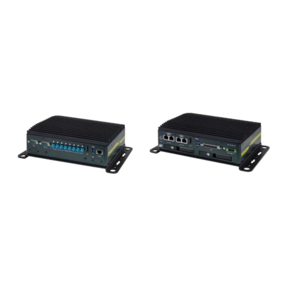
Neousys NRU series is an efficient fanless Edge AI inference platform that can deliver an equivalent of 120W GPU performances in under 30W of power consumption. NRU series can be tasked to perform video recording/ transcoding or real-time inference at the edge. It is ideal for... -
Page 11: Nru-110V Specifications
NRU Series NRU-110V Specifications System Core ™ Processor Supporting NVIDIA® Jetson AGX Xavier System-on-Module, comprising NVIDIA® Volta GPU and Carmel CPU On board 32GB LPDDR4x @ 2133 MHz on SoM Memory eMMC 32GB eMMC 5.1 on SoM I/O Interface ®... -
Page 12: Nru-120S Specifications
NRU Series NRU-120S Specifications System Core ™ Processor Supporting NVIDIA® Jetson AGX Xavier system-on-module, comprising of NVIDIA® Volta GPU and Carmel CPU Onboard 32GB LPDDR4x @ 2133 MHz Memory eMMC 32GB eMMC 5.1 on module I/O Interface PoE+ 4x IEEE 802.3at (25.5W) Gigabit PoE+ ports by Intel® I350 1x isolated CAN 2.0 port... -
Page 13: Dimension Of Nru Series
NRU Series Dimension of NRU Series NOTE All measurements are in millimeters (mm). The NRU-110V and NRU-120S share the same dimensions. 1.3.1 Front Panel View 1.3.2 Side Panel Views Left Right... -
Page 14: Rear Panel View
NRU Series 1.3.3 Rear Panel View 1.3.4 Bottom View... -
Page 15: Anti-Vibration Mount Dimensions
NRU Series 1.3.5 Anti-vibration Mount Dimensions... -
Page 16: System Overview
NRU Series System Overview Upon receiving and unpacking your NRU series systems, please check immediately if the package contains all the items listed in the following table. If any item(s) are missing or damaged, please contact your local dealer or Neousys Technology. -
Page 17: Nru Series Front Panel
NRU Series NRU Series Front Panel The front panel of NRU series feature rich I/O ports, it has four PoE+ Gigabit Ethernet ports, two USB 3.1 Gen1 ports, one DisplayPort, one digital I/O (1x GPS PPS input, 3-CH isolated DI and 4-CH isolated DO), ignition control switch and 3-pin terminal block for DC input. - Page 18 NRU Series isolated DI and 4-CH isolated DO Ignition control The switch allows for the configuration of ignition switch power on/ off delay by adjusting switch position. 3-pin terminal Compatible with DC power input from 8~35V, the block (DC/ terminal block is also used for ignition signal ignition control) input.
-
Page 19: Power Button
NRU Series 2.3.1 Power Button The power button is a non-latched switch for ATX mode on/off operation. Press to turn on the system, PWR LED should light up and to turn off, you can either issue a shutdown command in the OS, or just press the power button. In case of system halts, you can press and hold the power button for 5 seconds to force-shutdown the system. -
Page 20: Ieee 802.3At Power Over Ethernet Port (Nru-120S Only)
PoE+ ports will reduce from 100W to 68W. To increase the stability of NRU series, we have design an over current protection of 16A. In other words, if you expect to max out the power supply from PoE+ ports, please supply NRU... -
Page 21: System Status Led
NRU Series 2.3.4 System Status LED There are four LED indicators on the front panel: PWR, HDD and IGN. The descriptions of these four LEDs are listed in the following table. Indicat Color Description Green Power indicator, lid when system is on... -
Page 22: Displayport
NRU Series 2.3.5 DisplayPort The system has a DisplayPort (DP) output which is a digital display interface that mainly connect video source and carry audio to a display device. When connecting a DP, it can deliver up to 4K UHD (3840 x 2160 @ 30Hz) in resolution. -
Page 23: Hdd/ Ssd Hot-Swappable Tray (Nru-120S Only)
NRU Series 2.3.6 2.5” HDD/ SSD Hot-swappable Tray (NRU-120S Only) The system supports two external 2.5” HDD/ SSD via hot-swappable trays. Designed for easy access, the HDD trays are secured by a lock (indicated in red) and together. There is a disk connector insertion orientation (indicated in green) to avoid damaging the connectors during installation. -
Page 24: Dio Port
NRU Series 2.3.9 DIO Port The system provides 1x GPS PPS input, 3-CH isolated DI and 4-CH isolated DO output channels. The DO is followed by open-drain design, i.e., the output voltage is decided by the external power source. And we recommended to design the external power source between 5V to 24V. - Page 25 NRU Series unconnected DIO Script Sample In the following sample bash script, you can see how to access the DIO in Linux. # DIO GPIO Pin DO0=320 DO1=321 DO2=322 DO3=323 DI1=325 DI2=331 DI3=326 function exposeDI() { ## Expose DI to User Space echo $1 >/sys/class/gpio/export 2>/dev/null...
- Page 26 NRU Series exposeDI $DI3 ### Initial DO exposeDO $DO0 exposeDO $DO1 exposeDO $DO2 exposeDO $DO3 ### Set DO1 = 1 setDO $DO1 1 ### Set DO1 = 0 setDO $DO1 0 ### Save DI1 Value to DI_VALUE DI_VALUE=$(getDI $DI1)
-
Page 27: 2.3.10 Ignition Control Switch
NRU Series 2.3.10 Ignition Control Switch The ignition power control switch features multiple modes for pre and post ignition settings. Please refer to the section Ignition Power Control for details. 2.3.11 3-pin Terminal Block for DC and Ignition Control The system allows an 8 to 35V DC power input from via a 3-pin pluggable terminal block. -
Page 28: Nru Series Rear Panel
NRU Series NRU Series Rear Panel The rear panel of NRU systems feature a CAN bus, RS-232, DisplayPort, USB2.0 and a reserved micro-USB OTG port. The camera and 10GbE ports are only available on NRU-110V systems only. For demonstration purposes, NRU-110V will be used for most illustrations. - Page 29 NRU Series port only.. 10GbE 10GBASE-T 10G Ethernet port by Intel® X550-AT Ethernet controller. Available on NRU-110V only port...
-
Page 30: Can Bus Port
NRU Series 2.4.1 CAN bus Port CAN bus is a robust industrial bus with a pair of differential signals and is commonly used in various industrial and in-vehicles applications. The system is equipped with a CAN bus DB9 port that is compatible with both industrial and in-vehicle applications. The CAN bus port supports CAN2.0A and CAN2.0B up to 1Mbps. -
Page 31: Rs-232 Port
NRU Series 2.4.2 RS-232 Port The system has a RS-232 COM port for communicating with external devices. The port can be located on the rear panel via 9-pin D-Sub male connectors. RS-232 Port Reserved Reserved Reserved Reserved... -
Page 32: Camera Ports (Nru-110V Only)
NRU Series 2.4.3 Camera Ports (NRU-110V Only) The NRU-110V system features eight FAKRA Z male camera connection ports that support automotive camera sensors. Coupled with the unique onboard trigger system, it can simultaneously capture images from eight GMSL cameras within millisecond channel-to-channel skew. -
Page 33: Displayport
NRU Series 2.4.4 DisplayPort The system has a DisplayPort (DP) output which is a digital display interface that mainly connect video source and carry audio to a display device. Please use cable length within 1.8 meters when connecting a DP, the port can deliver up to 4K UHD (3840 x 2160 @ 30Hz) in resolution. -
Page 34: 10Gbe Ethernet Port (Nru-110V Only)
NRU Series 2.4.6 10GbE Ethernet Port (NRU-110V Only) Utilizing Intel’s X550-AT2 controller, the RJ45 10GBAST-T connector offers up to 10Gb bandwidth throughput over a maximum distance of 100 meters using Cat 6a or 55 meters using Cat 6 cables. It is ideal as a camera hub to deliver real-time image or video to other computers. -
Page 35: Internal I/O
NRU Series Internal I/O The system’s internal I/O connectors consist of an M.2 slot for NVMe SSD, mini PCIe slot and corresponding SIM slot. 2.5.1 M.2 2280 (M Key) Slot for NVMe SSD The system has an M.2 2280 slot (M key PCIe Gen3 x2) to install an NVMe SSD for the ultimate disk read/ write performance. - Page 36 NRU Series M.2 (M Key) Slot Pin Definition Pin # Signal Pin # Signal +3V3 +3V3 DAS/DSS_N +3V3 +3V3 +3V3 +3V3 PERN1 PERP1 PETN1 PETP1 PERn0 + PERp0 - PETn0 - PETp0 + PERST_N REFCLKN REFCLKP Mechanical Key SUSCLK PEDET...
-
Page 37: Mini-Pcie & Sim Slot
NRU Series 2.5.2 mini-PCIe & SIM Slot This mini-PCIe socket works (indicated in blue) in cooperation with the SIM slot (indicated in red). By installing a mini-PCIe module, you can add additional features to your system such as WIFI, GPS, CAN bus, analog frame grabber, etc. - Page 38 NRU Series mini-PCIe Pin Definition Pin # Signal Pin # Signal WAKE# +3.3Vaux COEX1 COEX2 +1.5V CLKREQ# UIM_PWR UIM_DATA REFCLK- UIM_CLK REFCLK+ UIM_RESET UIM_VPP Mechanical Key Reserved* (UIM_C8) Reserved* (UIM_C4) W_DISABLE# PERST# PERn0 +3.3Vaux PERp0 +1.5V SMB_CLK PETn0 SMB_DATA PETp0...
-
Page 39: System Installation
NRU Series System Installation Before disassembling the system enclosure and installing components and modules, please make sure you have done the following: It is recommended that only qualified service personnel should install and service this product to avoid injury or damage to the system. -
Page 40: Disassembling The System Enclosure
NRU Series Disassembling the System Enclosure To install internal components such as M.2 SSD or mini-PCIe module, you need to disassemble the system enclosure. Please refer to the following procedure: 1. Turn the system upside-down and remove the six screws indicated. - Page 41 NRU Series 3. With the system remaining upside-down, remove the two screws indicated on the front panel. 4. Remove the eight screws (4 per side) indicated on both sides of the system.
- Page 42 NRU Series 5. Remove the two screws indicated on the rear panel. 6. Remove the two screws indicated.
- Page 43 NRU Series 7. Gently pull apart the enclosure.
-
Page 44: Installing Internal Components
NRU Series Installing Internal Components 3.2.1 mini-PCIe and SIM Card Installation There is one mini-PCIe and a SIM card slot on the main board. Please follow the procedures for installation. Disassembling the system enclosure. 2. Locate the mini-PCIe slot indicated in blue and the SIM card slot indicated in... - Page 45 NRU Series 3. To install, insert the gold finger end of the mini-PCIe card on a 45 degree angle into the slot, gently push the other end of the mini-PCIe onto the motherboard and secure it with two screws. 45 degree angle insert Secure the card with a screw 4.
-
Page 46: 2880 M Key Nvme Ssd Installation
NRU Series 3.2.2 M.2 2880 M Key NVMe SSD Installation There is one M.2 2280 M Key slot (PCIe Gen3 x2) for you to install an NVMe SSD. Please follow the procedures below to install the M.2 module. Disassemble the system enclosure. - Page 47 NRU Series 3. Insert the NVMe SSD into the slot on a 45° angle. 4. Gently push it towards the motherboard and secure the NVMe SSD with the supplied screw.
- Page 48 NRU Series 5. Once the NVMe SSD has been secured, reinstall the internal panel by securing the screws on both sides. Reinstall the enclosure when done.
-
Page 49: Installing The System Enclosure
NRU Series Installing the System Enclosure To reinstall the system enclosure, with system upside-down (the heatsink fins at the bottom). Merge the front and rear panel enclosures together while making sure the connection ports meet the front and rear openings. - Page 50 NRU Series Secure the two screws that hold the front and rear enclosure panels together. Secure the two screws indicated on the front panel. 4. Secure the two screws indicated on the rear panel.
- Page 51 NRU Series 5. Secure the eight screws (4 per side) indicated on both sides of the system. 6. Gently slide the bottom panel into place.
- Page 52 NRU Series 7. Secure the bottom panel with six screws (four screws secure the four rubber stands).
-
Page 53: Anti-Vibration Mount Installation
NRU Series Anti-vibration Mount Installation The system comes with an anti-vibration mount. To install the anti-vibration mount, please remove the four rubber stands at the bottom of the enclosure. - Page 54 NRU Series To install, secure the anti-vibration mount to the bottom of the system enclosure using the provided M4 screws (indicated in red) and sleeves (indicated in blue). Make sure you secure the system on a flat surface. The illustration shows...
-
Page 55: Powering On The System
NRU Series Powering On the System 3.5.1 Powering On Using the Power Button This is the simplest way to turn on your system. The power button on the side panel is a non-latched switch and behaves as the ATX-mode on/off control. With DC power connected, pushing the power button will turn on the system and the PWR LED indicator will light up. -
Page 56: Ignition Power Control
NRU Series Ignition Power Control The ignition power control module for in-vehicle applications is an MCU-based implementation that monitors the ignition signal and reacts to turn on/off the system according to predefined on/off delay. Its built-in algorithm supports other features such as ultra-low power standby, battery-low protection, system hard-off, etc. - Page 57 NRU Series Once power-off delay expired, another PWRBTN# pulse is issued to perform a soft-off for the system (ex. a normal shutdown process for Windows system). 10. The system is completely shut down. 11. As MCU detects system is off, it turns off the standby power for the system,...
-
Page 58: Additional Features Of Ignition Power Control
NRU Series 4.1.1 Additional Features of Ignition Power Control In addition to the typical timing correlation, the ignition power control module offers additional features to provide additional reliability for in-vehicle applications. Low battery detection The ignition power control module continuously monitors the voltage of DC input when the system is operational. -
Page 59: Wiring Ignition Signal
NRU Series 4.1.2 Wiring Ignition Signal To have ignition power control for in-vehicle usage, you need to supply IGN signal to the system. The IGN input is located on the 3-pin pluggable terminal block (shared with DC power input). For in-vehicle ignition control wiring, please do the following: 1. -
Page 60: Operation Modes Of Ignition Power Control
NRU Series 4.1.3 Operation Modes of Ignition Power Control You can use the rotary switch to configure the operation mode. The system offers 16 (0~15) operation modes with different power-on/power-off delay configurations. Ignition rotary switch location on the front panel Ignition rotary switch ... - Page 61 NRU Series Mode 3 ~ Mode 12 Mode 3 ~ Mode 12 have various power-on delay and power-off delay. Each mode supports a hard-off timeout of 10 minutes. Mode Power-on Delay Power-off Delay Hard-off Timeout 10 seconds 10 seconds...
-
Page 62: Reflashing The Nru System
NRU Series Reflashing the NRU System NRU series is shipped with JetPack 4.4 installed as a turnkey solution. If you are familiar and experienced with the platform, you can skip this section and start your development. This section will show you how to reflash the NRU series with either NVIDIA's official JetPack 4.4 or from the pre-built system image by Neousys. -
Page 63: Prerequisites
• 1x NRU system with NVIDIA Jetson Xavier 32GB Module • 1x NRU Series barebone and power supply Prepare Host Machine for Reflash Process Install Ubuntu 18.04.02 LTS [link]. Create a bootable USB stick and finish the Ubuntu 18.04.02 setup process [link]. -
Page 64: Prepare Target Machine For Reflash Process
NRU Series Prepare Target Machine for Reflash Process To reflash your NRU system, please refer to the following steps: Make sure you set the ignition switch to mode 0. Connect the 3-pin terminal plug. Connect the USB cable between the host and target machine. - Page 65 NRU Series Boot the target machine (NRU) in recovery mode: Make sure the NRU system is off. Press the hold the force recovery button C. Press the power button D. 5 seconds later, release the force recovery button Confirm NRU is in recovery mode using lsusb on your host machine.
-
Page 66: Reflashing The Nru System
To beginning reflashing the NRU system, enter the following command in the terminal to update the package list on the host machine: sudo apt-get update We will flash a NRU series by SDK Manager once to finish necessary settings on Host Machine. After this session, you will get a flash.sh command-line tool. - Page 67 NRU Series If the "Detected" is not shown under the Jetson AGX Xavier, you may need to refer to the previous step to put your NRU system into Recovery Mode. JetPack 4.4 (NOT JetPack 4.4 DP)
- Page 68 NRU Series At STEP 02, click on the Jetson OS, and the "I accept the terms ..." in the bottom of SDK Manager and press continue. The flash process may take a while and when complete, you will find a signed "flash.sh"...
-
Page 69: Reflash Neousys' Pre-Built System Image
NRU Series Reflash Neousys’ Pre-built System Image Flash via this method if you wish to reset your NRU system to the original factory settings. Download .dtb and .img files from NRU FTP. Boot your NRU system into recovery mode (click here for details) .dtb... -
Page 70: Reflash Nru System Using Nvidia's Sdk Manager
After the GUI process, you will find your NRU without display output signal. This is because the official NVIDIA dtb doesn't 100% fit the hardware design of NRU series. • Device Tree - It helps the Xavier module understand the hardware design. -
Page 71: Backup Your File System Image
NRU Series Backup Your File System Image As an edge AI platform, if you have made yourself a stable NRU development environment. We would recommend you to make your own File System Image as your backup. By following steps, you can create your own System Image on your Host machine. - Page 72 NRU Series # Move Raw Image to L4T/bootloader cd $L4T_ROOT_J4_4/bootloader mv ~/$SYS_IMG_RAW.raw . # Make Sparase Image ./mksparse -v --fillpattern=0 $SYS_IMG_RAW.raw $SYS_IMG_RAW.img # System Image is Ready, and replace for the default path for File System Flash! cp $SYS_IMG_RAW.img system.img Refer to "Reflash Neousys' Pre-built System...
-
Page 73: Software Reminder
NRU Series Software Reminder In this section, we would like to introduce our built-in camera driver (NRU-110V) only, and some usage and feedback from our early adopters. GMSL Camera Driver and Utility (NRU-110V Only) We have put two demo folders on the pre-installed system image.
Need help?
Do you have a question about the NRU Series and is the answer not in the manual?
Questions and answers