
Related Manuals for Neousys Technology Nuvo-8240GC Series


Summary of Contents for Neousys Technology Nuvo-8240GC Series
- Page 1 | 866-412-6278 | info@coastipc.com Neousys Technology Inc. Nuvo-8240GC Series User Manual Revision 1.1...
-
Page 2: Table Of Contents
Table of Contents Table of Contents Table of Contents ........................2 Legal Information ........................4 Contact Information ....................... 5 Declaration of Conformity ..................... 5 Copyright Notice ........................6 Safety Precautions......................... 7 Hot Surface Warning......................7 Battery Warning........................ - Page 3 Table of Contents 3.2.4 M.2 2242 (B Key) Module and Micro-SIM (3FF) Card Installation ..... 58 ® 3.2.5 M.2 2280 NVMe SSD or Intel Optane Memory Installation ......61 3.2.6 2.5” Hot-swappable HDD/ SSD Installation ............63 3.2.7 2.5” HDD/SSD Installation ................65 ®...
-
Page 4: Legal Information
For questions in regards to hardware/ software compatibility, customers should contact Neousys Technology Inc. sales representative or technical support. To the extent permitted by applicable laws, Neousys Technology Inc. shall NOT be responsible for any interoperability or compatibility issues that may arise when (1) products, software, or options not certified and supported;... -
Page 5: Contact Information
Neousys Technology Inc. (Taipei, Taiwan) 15F, No.868-3, Zhongzheng Rd., Zhonghe Dist., New Taipei City, 23586, Taiwan Tel: +886-2-2223-6182 Fax: +886-2-2223-6183 Email, Website Americas Neousys Technology America Inc. 3384 Commercial Avenue, Northbrook, IL 60062, USA (Illinois, USA) Tel: +1-847-656-3298Email, Website China Neousys Technology (China) Ltd. -
Page 6: Copyright Notice
This manual is intended to be used as an informative guide only and is subject to change without prior notice. It does not represent commitment from Neousys Technology Inc. Neousys Technology Inc. shall not be liable for any direct, indirect, special, incidental, or consequential damages arising from the use of the product or documentation, nor for any infringement on third party rights. -
Page 7: Safety Precautions
24Vdc, 16A, Tma 60 degree C and 5000m altitude during operation. If further assistance is required, please contact Neousys Technology If the system is not going to be used for a long time, disconnect it from mains... -
Page 8: Service And Maintenance
Service and Maintenance/ ESD Precautions Service and Maintenance ONLY qualified personnel should service the system Shutdown the system, disconnect the power cord and all other connections before servicing the system When replacing/ installing additional components (expansion card, memory module, etc.), insert them as gently as possible while assuring proper connector engagement ESD Precautions... -
Page 9: About This Manual
About This Manual About This Manual ® This manual introduces Neousys Nuvo-8240GC series featuring Intel Core™ I hexa/ octa core 35W/ 65W LGA1151 processors and an NVIDIA graphics ® card. The Nuvo-8240GC system supports dual NVIDIA Tesla T4 inference accelerators for excellent deep learning performances. -
Page 10: Introduction
Nuvo-8240GC Introduction Nuvo-8240GC is a rugged edge AI platform designed specifically to support dual NVIDIA® Tesla T4s for advanced inference acceleration applications. It features NVIDIA multi-precision Turing Tensor Cores and new RT Cores while offering tremendous GPU power up to 130 TFLOPS in FP16 and 520 TOPS in INT4 for emerging GPU-accelerated edge computing and advanced AI inference. -
Page 11: Product Specifications
Nuvo-8240GC Series Product Specifications 1.1.1 Nuvo-8240GC Specifications System Core Supporting Intel® Xeon® E and 8 Gen CPU (LGA1151 socket) Intel® Xeon® Processor E-2176G/ 2278GE (8C/16T) / 2278GEL (8C/16T) Intel® Core™ i7-9700E/ i7-9700TE Intel® Core™ i7-8700/ i7-8700T Processor Intel® Core™ i5-9500E/ i5-9500TE Intel®... - Page 12 Nuvo-8240GC 2x PCIe x8 slots@Gen3, 4-lanes 1x M.2 2242 B key socket supporting dual SIM mode with selected M.2 LTE module Mini-PCIe 2x full-size mini PCI Express socket Power Supply DC Input 1x 4-pin pluggable terminal block for 8~48V DC input with ignition control Mechanical Dimension 190 (W) x 270 (D) x 198 (H)
-
Page 13: Nuvo-8240Gc Dimension
Nuvo-8240GC Series Nuvo-8240GC Dimension NOTE All measurements are in millimeters (mm). 1.2.1 Nuvo-8240GC I/O Panel View... -
Page 14: Nuvo-8240Gc 4-Pin Terminal Block Panel View
Nuvo-8240GC 1.2.2 Nuvo-8240GC 4-Pin Terminal Block Panel View... -
Page 15: Nuvo-8240Gc Top Panel View
Nuvo-8240GC Series 1.2.3 Nuvo-8240GC Top Panel View 1.2.4 Nuvo-8240GC Heatsink Panel View... -
Page 16: Nuvo-8240Gc Bottom View
Nuvo-8240GC 1.2.5 Nuvo-8240GC Bottom View... -
Page 17: System Overview
Upon receiving and unpacking your Nuvo-8240GC system, please check immediately if the package contains all the items listed in the following table. If any item(s) are missing or damaged, please contact your local dealer or Neousys Technology. Nuvo-8240GC Packing List... -
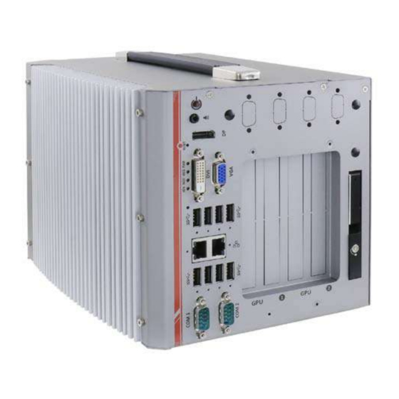
Page 18: External I/O Panel
Nuvo-8240GC External I/O Panel The Nuvo-8240GC I/O panel features Gen2/ Gen1 USB3.0, DisplayPort, DVI, VGA, dual Ethernet and COM ports. Item Description Power Use this button to turn on or shutdown the system. button Speaker-out Speaker-out jack for sound output. 3.5mm jack Support display resolutions up to 4096 x 2304. - Page 19 Nuvo-8240GC Series VGA port VGA output supports resolution up to 1920x1200@60Hz USB3.1 Gen 2 port (SuperSpeed+) offers up to 10Gbps, twice the USB 3.1 bandwidth over existing SuperSpeed USB3.1 Gen. 1 connection. It is Gen2 port also backwards compatible with USB3.0 and USB2.0 1x Gigabit Ethernet port by Intel®...
-
Page 20: Power Button
Nuvo-8240GC 2.2.1 Power Button The power button is a non-latched switch for ATX mode on/off operation. To turn on the system, press the power button and the PWR LED should light-up green. To turn off the system, issuing a shutdown command in OS is preferred, or you can simply press the power button. -
Page 21: Mm Speaker/ Headphone Output Jack
Nuvo-8240GC Series 2.2.2 3.5mm Speaker/ Headphone Output Jack The system audio function uses high definition audio. There is a female 3-pole audio jack for headphone (speaker) output. To utilize the audio function in Windows, you need to install ® corresponding drivers for both Intel... -
Page 22: Displayport
Nuvo-8240GC 2.2.3 DisplayPort The DisplayPort (DP) output is a digital display interface that mainly connect video source and carry audio to a display device. When connecting a DP, it can deliver up to 4K UHD (4096 x 2304) in resolution. The system is designed to support passive DP adapter/ cable. You can connect to other display devices using DP-to-HDMI cable or DP-to-DVI cable. -
Page 23: Reset Button
Nuvo-8240GC Series 2.2.4 Reset Button The reset button is used to manually reset the system in case of system halt or malfunction. To avoid unexpected reset, the button is purposely placed behind the panel. To reset, please use a pin-like object (eg. tip of a pen) to access the reset button... -
Page 24: Led Indicators
Nuvo-8240GC 2.2.5 LED Indicators There are four LED indicators on the I/O panel: PWR, HDD, WDT and IGN. The descriptions of these four LED are listed in the following table. Indicator Color Description Green Power indictor, lid when system is on. Hard drive indicator, flashing when hard disk drive is active. -
Page 25: Dvi Port
Nuvo-8240GC Series 2.2.6 DVI Port DVI-D transmits graphics data in digital format and therefore can deliver better image quality at high resolution. The DVI connector on the front panel can either output DVI signals or other digital signals (via an adapter/ cable) depending on the display device connected. It supports resolutions up to 1920x1200@60Hz. -
Page 26: Vga Port
Nuvo-8240GC 2.2.7 VGA Port VGA connector is the most common video display connection. The VGA output supports up to 1920x1200@60Hz resolution. The system supports triple independent display outputs by connecting display devices to VGA, DVI and DisplayPort. To support multiple display outputs and achieve best VGA output resolution in Windows, you need to install corresponding graphics drivers. -
Page 27: Usb3.1 Gen 2 Port
Nuvo-8240GC Series 2.2.8 USB3.1 Gen 2 Port The system’s USB 3.1 Gen 2 ports (10Gbps) are implemented via native xHCI (eXtensible Host Controller Interface) controller and are backward compatible with USB3.1 Gen.1 USB 2.0, USB 1.1 and USB 1.0 devices. Legacy USB is also supported so you can use USB keyboard/mouse in DOS environment. -
Page 28: Gigabit Ethernet Port
Nuvo-8240GC 2.2.9 Gigabit Ethernet Port The system offers 2 GbE ports on its I/O panel. The GbE ports are marked in blue/ ® ® are implemented with Intel I219-LM/ Intel I210-IT controllers, respectively. Each port has one dedicated PCI Express link for maximum performance. When an Ethernet connection is established, the LED indicators on the RJ45 connector represents the following connection statuses: Active/Link LED... -
Page 29: 2.2.10 Usb3.1 Gen 1 Port
Nuvo-8240GC Series 2.2.10 USB3.1 Gen 1 Port The system’s USB 3.0 Gen 1 ports (5Gbps) are implemented via native xHCI (eXtensible Host Controller Interface) controller and are backward compatible with USB 2.0, USB 1.1 and USB 1.0 devices. Legacy USB is also supported so you can use USB keyboard/mouse in DOS environment. -
Page 30: 2.2.11 Com Port
Nuvo-8240GC 2.2.11 COM Port The two COM ports are implemented using industrial-grade ITE8786 Super IO chip (-40 to 85°C) and provide up to 115200 bps baud rate. COM1 and COM2 (in red) are software-configurable RS-232/422/485 ports. COM3 and COM4 (in blue) are standard 9-wire RS-232 ports. The operation mode of COM1 and COM2 can be set in BIOS setup utility. -
Page 31: 2.2.12 2.5" Hdd/ Ssd Hot-Swappable Tray
Nuvo-8240GC Series 2.2.12 2.5” HDD/ SSD Hot-swappable Tray The system has an external 2.5” HDD/ SSD via a hot-swappable tray. Designed for easy access, the HDD/ SSD slot is secured by a lock (indicated in red)and it supports RAID modes 0/ 1 configuration by combining with the internal HDD/ SSD drive for OS installation (coupled with the internal HDD). -
Page 32: Ignition/ Dual 4-Pin Terminal Block
Nuvo-8240GC Ignition/ Dual 4-Pin Terminal Block The system accepts a wide range of DC power input from 8 to 48V via a 4-pin pluggable terminal block, which is fit for field usage where DC power is provided. The screw clamping mechanism on the terminal block offers connection reliability when wiring DC power. -
Page 33: Ignition Control Switch
Nuvo-8240GC Series Ignition Control Switch The ignition power control switch features multiple modes for pre and post ignition settings. Please refer to the section Ignition Power Control for details. Please use a flathead screwdriver to adjust the position of the ignition power control switch. -
Page 34: Internal I/O Functions
Nuvo-8240GC Internal I/O Functions In addition to I/O connectors on the front panel, the system also provides internal on-board connectors, such as remote on/off control, LED status output, internal USB 2.0 ports, etc. In this section, we’ll illustrate these internal I/O functions. 2.5.1 Dual SODIMM DRAM Slot The system motherboard supports four 260-pin SODIMM socket for installing DDR4 memory... -
Page 35: Dual Mode Msata/ Mini-Pcie Socket & Pin Definition
Nuvo-8240GC Series 2.5.2 Dual Mode mSATA/ mini-PCIe Socket & Pin Definition The system provides a dual mode mSATA/ mini-PCIe socket (indicated in blue) that is in compliance with mini-PCIe specification rev. 1.2. You can install either an mSATA SSD or mini-PCIe module into this socket and the system will automatically detect and configure it to run PCIe or SATA signals. - Page 36 Nuvo-8240GC Dual mode mSATA/ mini-PCIe socket definition Signal (mPCIe) Signal (mSATA) Pin # Signal (mPCIe) Signal (mSATA) WAKE# +3.3Vaux 3.3V +1.5V +1.5V CLKREQ# UIM_PWR UIM_DATA REFCLK- UIM_CLK REFCLK+ UIM_RESET UIM_VPP Mechanical Key Reserved* Reserved* W_DISABLE# PERST# PERn0 SATA_Rxp 3.3V 3.3V PERp0 SATA_Rxn +1.5V...
-
Page 37: 2242 (B Key), Mini-Sim Card Slot & Pin Definition
Nuvo-8240GC Series 2.5.3 M.2 2242 (B Key), Mini-SIM Card Slot & Pin Definition NOTE The dual SIM card functionality is only available when Sierra Wireless EM7455/ 7430 solution is installed. For other 4G add-on solutions, SIM card slot 1 is the default functioning slot. - Page 38 Nuvo-8240GC M.2 (B Key) Slot Pin Definition Pin # Signal Pin # Signal +3V3 +3V3 FULL_CARD_POWER_OFF_N USB_D+ W_DISABLE_N USB_D- Mechanical Key USB3.0-RX- USB3.0-RX+ UIM1-RESET UIM1-CLK USB3.0-TX- UIM1-DATA USB3.0-TX+ UIM1-PWR PERn0 / SATA-B+ UIM2-DET PERp0 / SATA-B- UIM2-DATA UIM2-CLK PETn0 / SATA-A- UIM2-RST PETp0 / SATA-A+ UIM2-PWR...
-
Page 39: Sata Ports
Nuvo-8240GC Series 2.5.4 SATA Ports NOTE Supports up to 15mm thickness HDD/ SSD. The system provides two SATA ports which support Gen3, 6 Gb/s SATA signals. Each SATA port (indicated in blue) features a 7-pin SATA connector and a 4-pin power connector. -
Page 40: On/ Off Ctrl & Status Output
Nuvo-8240GC 2.5.5 On/ Off Ctrl & Status Output Pin# Definition Description WDT_LED- [Output] Watchdog timer indicator, flashing when Watchdog WDT_LED+ timer is active Standby Power- [Output] Standby power indicator, on if DC power is applied and system is in S5 (standby) mode. Standby Power+ HDD- [Output] Hard drive indicator, flashing when SATA hard... -
Page 41: Internal Usb 2.0 Port
Nuvo-8240GC Series 2.5.6 Internal USB 2.0 Port The system’s daughter board has an internal USB2.0 port on the PCBA. You can utilize this USB port to connect a USB protection dongle inside the chassis of the system. -
Page 42: Memory
Nuvo-8240GC 2.5.7 M.2 2280 (M Key) Slot for NVMe SSD or Optane Memory The system has anx4 PCIe M.2 2280 slot (also in compliance with SATA signal) for you to ® install an NVMe SSD for the ultimate performance or an Intel Optane memory to accelerate the read/ write performances of traditional hard disk drive. - Page 43 Nuvo-8240GC Series M.2 (M Key) Slot Pin Definition Pin # Signal Pin # Signal +3V3 +3V3 PERN3 PERP3 DAS/DSS_N PETN3 +3V3 PETP3 +3V3 +3V3 PERN2 +3V3 PERP2 PETN2 PETP2 PERN1 PERP1 PETN1 PETP1 PERn0 / SATA-B+ PERp0 / SATA-B- PETn0 / SATA-A-...
-
Page 44: System Installation
Nuvo-8240GC System Installation Before disassembling the system enclosure and installing components and modules, please make sure you have done the following: It is recommended that only qualified service personnel should install and service this product to avoid injury or damage to the system. ... -
Page 45: Disassembling The Enclosure
Nuvo-8240GC Series Disassembling the Enclosure To access system internal components, the system needs to be disassembled. To disassemble the system enclosure, you need to remove the following: Remove the screws indicated in blue on the I/O panel. Remove the screws indicated in blue on the side panel. - Page 46 Nuvo-8240GC Remove the screws indicated in blue on the top panel. Remove the screws indicated in blue on the fan intake panel. Notice the screw indicated in red, only remove this screw if you wish to remove the fan as well.
- Page 47 Nuvo-8240GC Series Using the handle on top, gently lift the L-shaped enclosure. You will see an internal panel indicated in green that needs to be removed before you can access the internal components. To do so, remove the screws indicated in...
- Page 48 Nuvo-8240GC Gently pull and slide the extension board out of the enclosure to gain access to internal expansion slots.
-
Page 49: Installing Internal Components
Nuvo-8240GC Series Installing Internal Components 3.2.1 CPU Installation Procedure To install the CPU, you will need to separate the heatsink and the motherboard. To do so, please refer to the Disassembling the Enclosure section. Separate the motherboard and heatsink from the enclosure by removing the hex-bolt... - Page 50 Nuvo-8240GC Next step is to separate the motherboard from the heatsink. Remove the screws indicated below (if you are installing the CPU for the first time, you need not remove the screws indicated in as they are not yet installed and the screws can be found in the accessory box).
- Page 51 Nuvo-8240GC Series Remove the CPU from its container/ tray. Match the two notches on the side to the protrusions in the socket, gently lower the CPU into the socket. Locate the CPU retention bracket from the accessory box. Place the retention bracket on...
- Page 52 Nuvo-8240GC Turn the motherboard around and secure the bracket by tightening two M3 P-head screws. Remove all thermal pads’ protective films on the heatsink. With the four motherboard standoffs aligned, gently lower the motherboard onto the heatsink and secure the screws indicated. If you need to install other components, please refer to respective sections.
- Page 53 Nuvo-8240GC Series 10. Once the motherboard has been installed, you’re ready to secure the six spring screws found in the accessory box) that help the heatsink apply pressure to the CPU/ chipset die. You’ll want to apply even pressure to the corners by gradually tightening each screw.
-
Page 54: Ddr4 So-Dimm Installation
Nuvo-8240GC 3.2.2 DDR4 SO-DIMM Installation There are two SO-DIMM memory slots (indicated in blue) on the motherboard that supports a total maximum of 64GB DDR4-2666. Please follow the procedures below to replace or install the memory modules. 1. Please refer to the section “Disassembling the System”. - Page 55 Nuvo-8240GC Series 4. Push the memory module down until it is clipped-in. 5. Repeat steps 3 and 4 to install the other module. Reinstall the system enclosure and panel when done. 7. If you need to install other components, please refer to respective sections.
-
Page 56: Mpcie Module, Mini-Sim (2Ff) Card And Antennae Installation
Nuvo-8240GC 3.2.3 mPCIe Module, Mini-SIM (2FF) Card and Antennae Installation The system has an mPCIe slot (indicated in blue)coupled with Mini-SIM socket (indicated in red)for installing 3G/ 4G module. For installation, please refer to the following instructions. Please refer to the section “Disassembling the System”. - Page 57 Nuvo-8240GC Series Insert the mPCIe module on a 45 degree angle into the mPCIe slot and secure the module. Insert on 45 degree angle Secure the module Clip on the IPEZ-to-SMA cable to the module and secure the antenna connector body to the panel and install the antenna.
-
Page 58: 2242 (B Key) Module And Micro-Sim (3Ff) Card Installation
Nuvo-8240GC 3.2.4 M.2 2242 (B Key) Module and Micro-SIM (3FF) Card Installation The system has an M.2 slot (indicated in blue) for installing 3G/ 4G or a WiFi module that can be coupled with dual Micro-SIM card slots (indicated in red). For installation, please refer to the following instructions. - Page 59 Nuvo-8240GC Series Secure the SIM card by sliding the holder. Insert the module on a 45 degree angle. Gently press down and secure the module with an M2.5 P-head screw.
- Page 60 Nuvo-8240GC Clip on the IPEZ-to-SMA cable to the module and secure the antenna connector body to the panel and install the antenna. Please refer to the module’s manual for clip-on connection. Clip on IPEZ-to-SMA cable Secure antenna to rear panel Install antenna Reinstall the system enclosure and panel when done.
-
Page 61: 2280 Nvme Ssd Or Intel Optane Memory Installation
Nuvo-8240GC Series ® 3.2.5 M.2 2280 NVMe SSD or Intel Optane Memory Installation The system has a x4 PCIe M.2 2280 slot for you to install an NVMe SSD for the ultimate performance or an Intel® Optane memory to accelerate the read/ write performances of traditional hard disk drive. - Page 62 Nuvo-8240GC Gently press down and secure the module with an M2.5 P-head screw. Reinstall the system enclosure and panel when done. If you need to install other components, please refer to respective sections. ® Please refer to the section Intel Optane Memory BIOS Setup and Driver Installation for traditional hard drive acceleration.
-
Page 63: Hot-Swappable Hdd/ Ssd Installation
Nuvo-8240GC Series 3.2.6 2.5” Hot-swappable HDD/ SSD Installation NOTE Supports up to 15mm thickness HDD/ SSD. The system features a 2.5” external hot-swappable HDD/ SSD slot. To install HDD/ SSD into the 2.5” external hot-swappable slot, please refer to the following procedures. - Page 64 Nuvo-8240GC Push the handle into the 2.5” slot until it snaps into position. A key is provided (in accessory box) to lock the external slot. Key in accessory box 2.5” HDD/ SSD slot lock...
-
Page 65: Hdd/Ssd Installation
Nuvo-8240GC Series 3.2.7 2.5” HDD/SSD Installation The system has a 2.5” HDD/ SSD tray that can be accessed from the bottom of the enclosure. To install a hard drive to the try, please refer to the following procedures. From the accessory box, find the two HDD/ SSD padding and stick it onto the edges of the HDD/ SSD. - Page 66 Nuvo-8240GC With the label facing up, place the HDD/ SSD into the tray and secure it onto the tray, there are four screws (two on each side). Connect the cable to the HDD/ SSD. Tuck the cables into the enclosure, secure the HDD/ SSD and tray back into the enclosure.
-
Page 67: Nvidia Tesla T4 Installation
Nuvo-8240GC Series ® 3.2.8 NVIDIA Tesla T4 Installation WARNING To reduce the risk of damage, DO NOT remove the graphics card from the antistatic bag before it is ready to be installed into the Cassette module! NOTE For installation compatibility, please consult with Neousys before purchasing a graphics card. - Page 68 Nuvo-8240GC Remove the Tesla T4 inference accelerator from the antistatic bag and gently lower it into the PCIe slot while ensuring the gold-fingers meet, graphics card panel is properly inserted. Secure the inference accelerator’s bezel. Repeat steps 2~5 if you need to install another inference accelerator. Reinstall the enclosure when done.
-
Page 69: Ethernet/ Poe+ Port Panel Screw Fix
Nuvo-8240GC Series 3.2.9 Ethernet/ PoE+ Port Panel Screw Fix The system's RJ45 Ethernet ports have panel screw fix holes (indicated in blue circles) for a firm cable connection. To install and make use to the panel screw fix connection, you must acquire panel screw fix cables such as the cable shown below. -
Page 70: Installing The System Enclosure
Nuvo-8240GC Installing the System Enclosure To reinstall the system enclosure, gently lower the internal panel while paying attention to the protruding corner of the fan indicated in red. You may need to loosen the fan’s screws if they are secured. Once the internal panel is in place, secure the two screws indicated in blue. - Page 71 Nuvo-8240GC Series Secure the screws on top of the enclosure indicated in blue. Secure the screws indicated in blue on the fan intake panel.
- Page 72 Nuvo-8240GC Secure the screws indicated in blue on the I/O panel to complete the enclosure installation.
-
Page 73: Powering On The System
Nuvo-8240GC Series Powering On the System There are three methods to power on the system Pressing the power button Sending a LAN packet via Ethernet (Wake-on-LAN) Powering on via ignition control (please refer to Ignition Control section) 3.4.1... -
Page 74: Powering On Using Wake-On-Lan
Nuvo-8240GC 3.4.2 Powering On Using Wake-on-LAN Wake-on-LAN (WOL) is a mechanism to wake up a computer system from a S5 (system off with standby power) state via issuing a magic packet. The system’s Wake-on-LAN compatible GbE port is shown below. NOTE Please make sure the Intel chipset and Ethernet driver has been properly installed prior to setting up WOL function. - Page 75 Nuvo-8240GC Series operating system. Once booted into the Windows system, press “Windows key + E”, right-click on “Network>Properties>Change adapter settings”. Locate and double-click on the adapter Intel® I219 Gigabit Network Connection, click on Configure... Click on the Power Management tab and check the following options.
-
Page 76: Ignition Power Control
Nuvo-8240GC Ignition Power Control The ignition power control module for in-vehicle applications is a MCU-based implementation that monitors the ignition signal and reacts to turn on/off the system according to predefined on/off delay. Its built-in algorithm supports other features such as ultra-low power standby, battery-low protection, system hard-off, etc. -
Page 77: Additional Features Of Ignition Power Control
Nuvo-8240GC Series 3.5.2 Additional Features of Ignition Power Control In addition to the typical timing correlation, the ignition power control module offers additional features to provide additional reliability for in-vehicle applications. 1. Low battery detection The ignition power control module continuously monitors the voltage of DC input when the system is operational. -
Page 78: Wiring Ignition Signal
Nuvo-8240GC 3.5.3 Wiring Ignition Signal To have ignition power control for in-vehicle usage, you need to supply IGN signal to the system. The IGN input is located on the 4-pin pluggable terminal block (shared with DC power input). Below is the typical wiring configuration for in-vehicle applications. Connect car Battery+ line (12V for sedan, 24V for bus/truck) to V+. -
Page 79: Configure Your Windows System
Nuvo-8240GC Series 3.5.4 Configure your Windows system When applying ignition power control to your system, please make sure you’ve configured your Windows system to initiate a shutdown process when pressing the power button. By default, Windows 7/ 8/ 10 goes to sleep (S3) mode when power button is pressed. As sleep... -
Page 80: Operation Modes Of Ignition Power Control
Nuvo-8240GC 3.5.5 Operation Modes of Ignition Power Control You can use the rotary switch to configure the operation mode. The system offers 16 (0~15) operation modes with different power-on/power-off delay configurations. The ignition control module is also BIOS-configurable. When rotary switch is set to mode 15 (0xF), the ignition power control is set to executed according to parameters configured in BIOS setup menu, which allows richer combination of power-on/ power-off delay and more detailed control parameters. - Page 81 Nuvo-8240GC Series Mode 3 ~ Mode 12 Mode 3 ~ Mode 12 have various power-on delay and power-off delay. Each mode supports a hard-off timeout of 10 minutes. Mode Power-on Delay Power-off Delay Hard-off Timeout 10 seconds 10 seconds...
-
Page 82: System Configuration
Nuvo-8240GC System Configuration BIOS Settings The system is shipped with factory-default BIOS settings meticulously programmed for optimum performance and compatibility. In this section, we’ll illustrate some of BIOS settings you may need to modify. Please always make sure you understand the effect of change before you proceed with any modification. -
Page 83: Com Port Configuration
Nuvo-8240GC Series 4.1.1 COM Port Configuration The system’s COM1/ COM2 ports support RS-232 (full-duplex), RS-422 (full-duplex) and RS-485 (half-duplex) mode. You can set the COM1 operating mode via BIOS settings. Another option in BIOS called “Slew Rate” defines how sharp the rising/falling edge is for the output signal of COM1. -
Page 84: Com Port High Speed Mode
Nuvo-8240GC 4.1.2 COM Port High Speed Mode The high speed mode of each COM port effectively allows for the port's baud rate generator to operate at 8x the speed with an effective baud rate of 921,600 bps (115,200 x 8). Please refer to the following instructions on how to enable the high speed mode for your COM port (COM1 used as an example). -
Page 85: Primary Display Selection
Nuvo-8240GC Series 4.1.3 Primary Display Selection With this setting, you manually select your choice of internal graphics card (IGFX), the add-on PCIe graphics card (PEG) or leave it on Auto. To set the primary display: 1. When system boots up, press F2 to enter BIOS setup utility. -
Page 86: Delay For Peg Initialization
Nuvo-8240GC 4.1.4 Delay for PEG Initialization This setting offers delay in milliseconds for PEG port initialization and PCI enumeration. By increasing the delay value, it may eliminate compatibility issue(s) with some PCIe add-on cards. To set PEG delay in milliseconds: 1. -
Page 87: Sata Configuration
Nuvo-8240GC Series 4.1.5 SATA Configuration The SATA controller of your system supports two (2) operating modes: AHCI and Intel RST Premium With Intel Optane System Acceleration mode. The AHCI mode, which exposes SATA's advanced capabilities such as hot swapping and native command queuing, is supported in several later version of operating systems. - Page 88 Nuvo-8240GC To set SATA controller mode: 1. When system boots up, press F2 to enter BIOS setup utility. 2. Go to [Advanced] > [SATA Configuration]. 3. Highlight the SATA, mSATA or M.2 port you wish to set and press ENTER to bring up setting options.
-
Page 89: Fan Control Configuration
Nuvo-8240GC Series 4.1.6 Fan Control Configuration The fan control configuration allows users to set the fan operation mode to auto or fixed speeds operation. The auto mode configuration also offers minimum temperature setting to trigger the fan and the maximum temperature setting before the fan operates at 100% rotation... - Page 90 Nuvo-8240GC To set Fan Control Configuration to Auto mode: When system boots up, press F2 to enter BIOS setup utility. Go to [Advanced] > [Fan Control Configuration] and press ENTER. To set auto fan control, highlight [Fan Control Mode] and press ENTER, highlight [Auto]...
- Page 91 Nuvo-8240GC Series Use the up/ down arrow keys to highlight Fan Start Trip Point or Fan Max. Trip Point and press ENTER, a window appears and you may enter the temperature in degree Celsius. Fan Start Trip Point: The minimum temperature which the fan being to operate ...
- Page 92 Nuvo-8240GC To set Fan Control Configuration to Fixed Speed mode: When system boots up, press F2 to enter BIOS setup utility. Go to [Advanced] > [Fan Control Configuration] and press ENTER. To set auto fan control, highlight [Fan Control Mode] and press ENTER, highlight [Fixed Speed].
- Page 93 Nuvo-8240GC Series Highlight [Fan Speed] and press ENTER. A window appears and you may use the up/ down arrow keys to select between 20~100% as your fixed fan rotation speed. When done, press F10 to “Exit Saving Changes”.
-
Page 94: Tpm Availability
Nuvo-8240GC 4.1.7 TPM Availability Trusted Platform Module (TPM) is a hardware-based cryptoprocessor to secure hardware by integrating cryptographic keys into devices. The system is designed with on-board TPM 2.0 module. As TPM 2.0 requires 64-bit Windows 7/8/10 with UEFI boot mode, it is disable in BIOS by default. -
Page 95: Power On After Power Failure Option
Nuvo-8240GC Series 4.1.8 Power On After Power Failure Option This option defines the behavior of System series when DC power is supplied. Value Description S0 – Power On System is powered on when DC power is supplied. S5 – Power Off System is kept in off state when DC power is supplied. -
Page 96: Power & Performance (Cpu Sku Power Configuration)
Nuvo-8240GC 4.1.9 Power & Performance (CPU SKU Power Configuration) The system supports various 8 -Gen Coffee Lake LGA1151 CPUs. A unique feature, “SKU Power Config” is implemented in BIOS to allow users to specify user-defined SKU power limit. Although the system is designed to have best thermal performance with CPUs of 35W TDP, you can install a 65W CPU and limit its SKU power (to 35W) to obtain more computing power. -
Page 97: 4.1.10 Wake On Lan Option
Nuvo-8240GC Series 4.1.10 Wake on LAN Option Wake-on-LAN (WOL) is a mechanism which allows you to turn on your System series via Ethernet connection. To utilize Wake-on-LAN function, you have to enable this option first in BIOS settings. Please refer “Powering On Using... -
Page 98: 4.1.11 Boot Menu
Nuvo-8240GC 4.1.11 Boot Menu The Boot menu in BIOS allows you to specify the system’s boot characteristics by setting bootable device components (boot media) and method. Or, you may press F12 upon system start up and select a device you wish boot from. Value Option Description... - Page 99 Nuvo-8240GC Series Enabled The system is available for network access using UEFI. Network Disabled The system is not available for network access using UEFI. Stack PXE Boot Disabled Only UEFI Network Stack is supported: Preboot eXecution capability Environment (PXE) is not supported...
-
Page 100: Boot Type (Legacy/ Uefi)
Nuvo-8240GC 4.1.12 Boot Type (Legacy/ UEFI) The system supports both Legacy and Unified Extensible Firmware Interface (UEFI) boot modes. UEFI is a specification proposed by Intel to define a software interface between operating system and platform firmware. Most modern operating systems, such as Windows 7/8/10 and Linux support both Legacy and UEFI boot modes. -
Page 101: 4.1.13 Position New Boot Device
Nuvo-8240GC Series 4.1.13 Position New Boot Device The “Add Boot Options” allow you to determine whether a newly added device (eg. USB flash disk) is to boot as the first device to boot or the last in the boot sequence. -
Page 102: 4.1.14 Watchdog Timer For Booting
Nuvo-8240GC 4.1.14 Watchdog Timer for Booting The watchdog timer secures the boot process by means of a timer. Once the timer expires, a reset command is issued to initiate another booting process. There are two options in BIOS menu, “Automatically after POST” and “Manually after Entering OS”. When “Automatically after POST”... -
Page 103: Legacy/ Uefi Boot Device
Nuvo-8240GC Series 4.1.15 Legacy/ UEFI Boot Device When you wish to set a designated boot device, you may set it as the first device to boot in Legacy or UEFI Boot Device setting. Or if you wish to manually select a boot device, you may do so by pressing F12 when the system boots up. -
Page 104: Amt Configuration
Nuvo-8240GC AMT Configuration Intel® AMT (Active Management Technology) is a hardware-based technology for remotely managing target PCs via Ethernet connection. The system supports AMT function via its Ethernet port implemented with Intel I219-LM. Prior to using the AMT function to remotely control the system, you need to configure AMT password and network settings. - Page 105 Nuvo-8240GC Series When the system boots up, press F10 to enter the MEBx configuration menu. Highlight MEBx Login and press Enter, a prompt will appear asking for password. The default password is “admin”. For further MEBx configuration details, please refer Intel®...
-
Page 106: Raid Configuration
Nuvo-8240GC RAID Configuration To set up a RAID 0 or 1 volume in Legacy or UEFI mode, you need to have at least two hard drives or SSDs installed. The system supports RAID configurations in RAID 0 (striping) or RAID 1 (mirror) mode. Users can select the configuration that best suit their needs with RAID 0 (striping) mode offering better hard drive read/ write performances while RAID 1 (mirror) offers better data security. - Page 107 Nuvo-8240GC Series 3. Go to [Boot] > highlight [Legacy Boot Type] and press ENTER to set boot type. 4. Press F10 to "Exit Saving Changes" and reboot the system. 5. When the system reboots, press [Ctrl + I] to enter the RAID configuration utility.
- Page 108 Nuvo-8240GC 7. The following screen allows you to enter the Name of the RAID volume you wish to create. Enter a name and press ENTER to access the RAID Level setting. 8. For RAID Level, use the up and down arrow key to select between RAID0 (Stripe) or RAID1 (Mirror) settings.
- Page 109 Nuvo-8240GC Series 9. For Stripe Size, use the up and down arrow key to select between 4KB, 8KB, 16KB, 32KB, 64KB, 128KB for your RAID volume stripe size and press ENTER to access the Capacity setting. *RAID1(Mirror) does not offer Stripe Size options.
- Page 110 Nuvo-8240GC 11. Reviewed your settings and if you wish to change any setting(s), you will need to press [ESC] and start again from Step 5.If all settings are correct and you wish to continue, with “Create Volume” highlighted, press ENTER to begin creating the RAID volume. 12.
- Page 111 Nuvo-8240GC Series 13. Once the RAID volume has been created, the configuration utility will bring you back to the main screen showing the RAID volume and their member disks. 14. The above process was to create a RAID-0 volume. If you wish to create a RAID-1 volume,...
-
Page 112: Uefi Mode Raid Configuration
Nuvo-8240GC 4.3.2 UEFI Mode RAID Configuration To enable RAID functionality in UEFI mode: 1. When system boots up, press F2 to enter BIOS setup utility. 2. Go to [Advanced] > [SATA And RST Configuration] > [SATA Mode Selection] > highlight [Intel RST Premium With Intel Optane System Acceleration] and press ENTER. - Page 113 Nuvo-8240GC Series 3. Go to [Boot], highlight [UEFI Boot Type] and press ENTER to set boot type. 4. Press F10 to “Exit Saving Changes” and reboot the system. 5. When the system reboots, press [F3] to enter the Configuration Utility.
- Page 114 Nuvo-8240GC 7. The following screen shows Non-RAID physical disks and the option “Create RAID Volume”. Highlight “Create RAID Volume” and press ENTER to begin creating your RAID volume.
- Page 115 Nuvo-8240GC Series 8. The Name option allows you to name your RAID volume. Press ENTER when ready to go to the next option.
- Page 116 Nuvo-8240GC 9. The RAID Level option allows you to select RAID-0 (stripping) or RAID-1 (mirror) for your RAID volume. Press ENTER when ready.
- Page 117 Nuvo-8240GC Series 10. The Select Disks option allows you to select disk drives for your RAID volume. Highlight a drive and press ENTER, use up/ down arrow keys to highlight “x” and press ENTER to confirm the selection. A minimum of two disk drives must be selected for RAID-0 or RAID-1...
- Page 118 Nuvo-8240GC 11. The Stripe Size option allows you to configure the stripe size of your RAID volume. Available stripe sizes are 4KB, 8KB, 16KB, 32KB, 64KB, 128KB, use the up and down arrow keys to highlight and press ENTER to confirm the stripe size selection. *RAID1(Mirror) does not offer Stripe Size options.
- Page 119 Nuvo-8240GC Series 12. The Capacity (MB) option allows you to configure the storage capacity of your RAID volume. By default, the full storage capacity will be applied. Once you have entered a capacity, press ENTER to confirm.
- Page 120 Nuvo-8240GC 13. The Create Volume option is the final step in the volume creation process. Highlight “Create Volume” and press ENTER to begin creating your RAID volume base on the settings you just configured.
- Page 121 Nuvo-8240GC Series 14. A summary and status of the RAID volume will be shown when the RAID volume is successfully created. 15. Press F10 to save and Esc to exit the Intel® Rapid Storage Technology configuration page. NOTE The above process was to create a RAID-0 volume. If you wish to create a RAID-1 volume,...
-
Page 122: Os Support And Driver Installation
Nuvo-8240GC OS Support and Driver Installation Operating System Compatibility The system supports most operating system developed for Intel® x86 architecture. The following list contains the operating systems which have been tested by Neousys Technology. Microsoft Window 10 (x64) ... -
Page 123: Driver Installation
Nuvo-8240GC Series Driver Installation The system comes with a “Drivers & Utilities” DVD that offers “one-click” driver installation process. It automatically detects your Windows operating system and installs all necessary drivers for you system with a single click. 5.2.1 Install Drivers Automatically The system comes with a “Drivers &... -
Page 124: Install Drivers Manually
Nuvo-8240GC 5.2.2 Install Drivers Manually You can also manually install each driver for the system. Please note when installing drivers manually, you need to install the drivers in the following sequence mentioned below. Windows 10 (x64) The recommended driver installation sequence is Chipset driver (x:\Driver_Pool\Chipset_10_APL\Win_ALL\SetupChipset.exe) Graphics driver (x:\Driver_Pool\Graphics_SKL_APL\Win_7_8_10_APL_64\Setup.exe) Audio driver (x:\Driver_Pool\Audio_ALC262\Win_ALL_64\Setup.exe) -
Page 125: Driver Installation For Watchdog Timer Control
Nuvo-8240GC Series Driver Installation for Watchdog Timer Control Neousys provides a driver package which contain function APIs for Watchdog Timer control function. You should install the driver package (WDT_DIO_Setup.exe) in prior to use these functions. Please note that you must install WDT_DIO_Setup_v2.2.9.x or later versions. -
Page 126: Intel ® Optane Tm Memory Bios Setup And Driver Installation
Nuvo-8240GC ® Intel Optane Memory BIOS Setup and Driver Installation ® The system is compatible with Intel Rapid Storage Technology that supports the installation ® of Intel Optane memory to significantly boost traditional hard disk drive read and write performances. Intel® Optane memory is Intel®... - Page 127 Nuvo-8240GC Series Go to “SATA Mode Selection”, press the Enter key to bring up options, select “Intel RST Premium With Intel Optane System Acceleration” and press ENTER to select the option.
- Page 128 Nuvo-8240GC Go to “M.2 2280 NVMe Storage Device” and press the Enter key to bring up the selection, select “RST Controlled” and press the Enter key to select the option. Press F10 to save and exit, and allow the system to boot into Windows. In Windows, download Intel®...
- Page 129 Nuvo-8240GC Series Follow the 6 step setup procedure as instructed.
- Page 130 Nuvo-8240GC Check the “I accept the terms in the License Agreement” box and click on “Next >” to continue the installation process.
- Page 131 Nuvo-8240GC Series When done, click on “Finish” and restart the system.
- Page 132 Nuvo-8240GC 10. Upon system restart, the following initialization screen will appear. Click on Next to continue. 11. In the Setup section, you will see your Intel® Optane™ memory drive and compatible drive(s) that can be accelerated. Click on the downward arrow to bring up a selection of drives to be accelerated.
- Page 133 Nuvo-8240GC Series 12. The data backup warning will appear, please backup any data you may have stored on your Intel® Optane™ memory module before proceeding. Check the box “Erase all data on Intel® Optane™ memory module” and click on Continue.
- Page 134 Nuvo-8240GC 14. Upon system restart, a successful enablement message will appear to indicate the Intel® Optane™ memory module has been enable successfully. 15. Once enabled, the RST software Setup section should show your configuration information.
-
Page 135: Appendix A Using Wdt & Dio
In this section, we’ll illustrate how to use the function library provided by Neousys to program the WDT functions. Currently, WDT driver library supports Windows 10 x64 and WOW64 platform. For other OS support, please contact Neousys Technology for further information. Installing WDT_DIO Library The WDT_DIO function library is delivered in the form of a setup package named WDT_DIO_Setup.exe. -
Page 136: Wdt And Dio Library Installation
Nuvo-8240GC WDT and DIO Library Installation To setup WDT & DIO Library, please follow instructions below. 1. Execute WDT_DIO_Setup.2.2.9.x.exe. and the following dialog appears. 2. Click “Next >” and specify the directory of installing related files. The default directory is C:\Neousys\WDT_DIO. - Page 137 Nuvo-8240GC Series 3. Once the installation has finished, a dialog will appear to prompt you to reboot the system. The WDT & DIO library will take effect after the system has rebooted. 4. When programming your WDT or DIO program, the related files are located in...
-
Page 138: Wdt Functions
Nuvo-8240GC WDT Functions InitWDT Syntax BOOL InitWDT(void); Description: Initialize the WDT function. You should always invoke InitWDT() before set or start watchdog timer. None Parameter Return Value TRUE: Successfully initialized FALSE: Failed to initialize BOOL bRet = InitWDT() Usage SetWDT Syntax BOOL SetWDT(WORD tick, BYTE unit);... -
Page 139: Startwdt
Nuvo-8240GC Series StartWDT Syntax BOOL StartWDT(void); Description Starts WDT countdown. Once started, the WDT LED indicator will begin blinking. If ResetWDT() or StopWDT is not invoked before WDT countdowns to 0, the WDT expires and the system resets. Parameter None...
Need help?
Do you have a question about the Nuvo-8240GC Series and is the answer not in the manual?
Questions and answers