Table of Contents
Advertisement
Quick Links
Advertisement
Table of Contents

Related Manuals for Neousys Technology Nuvo-2610VTC Series


Summary of Contents for Neousys Technology Nuvo-2610VTC Series
- Page 1 Neousys Technology Inc. Nuvo-2610VTC Series User Manual Revision 1.1...
-
Page 2: Table Of Contents
Table of Contents Table of Contents Table of Contents ........................2 Legal Information ........................5 Contact Information ....................... 6 Declaration of Conformity ..................... 6 Copyright Notice ........................7 Safety Precautions ......................... 8 Hot Surface Warning ......................8 Battery Warning ........................8 Service and Maintenance ...................... - Page 3 Damping Bracket for Nuvo-2610VTC Series ............85 3.6.1 Damping Bracket Installation for Nuvo-2610VTC ..........85 Damping Bracket Installation for Nuvo-2611VTC/ Nuvo-2612VTC ....... 87 Wall Mount Bracket for Nuvo-2610VTC Series (Optional) ........89 3.8.1 Wall-mount bracket for Nuvo-2610VTC ............89 3.8.2 Wall-mount Bracket for Nuvo-2611VTC/ Nuvo-2612VTC ........
- Page 4 Safety Precautions Appendix A Using WDT & DIO Watchdog Timer ......................... 120 Installing WDT_DIO Library ....................120 WDT and DIO Library Installation ..................121 WDT Functions ........................123 InitWDT ..........................123 SetWDT ..........................123 StartWDT ..........................124 ResetWDT ........................... 124 StopWDT ..........................
-
Page 5: Legal Information
For questions in regards to hardware/ software compatibility, customers should contact Neousys Technology Inc. sales representative or technical support. To the extent permitted by applicable laws, Neousys Technology Inc. shall NOT be responsible for any interoperability or compatibility issues that may arise when (1) products, software, or options not certified and supported;... -
Page 6: Contact Information
3384 Commercial Avenue, Northbrook, IL 60062, USA (Illinois, USA) Tel: +1-847-656-3298Email, Website China Neousys Technology China Co., Ltd. Room 429 /431, Building 32, Guiping Road 680, Shanghai, 200233, China Tel: +86-2161155366Email, Website Declaration of Conformity This equipment has been tested and found to comply with the limits for a Class A digital device, pursuant to part 15 of the FCC Rules. -
Page 7: Copyright Notice
This manual is intended to be used as an informative guide only and is subject to change without prior notice. It does not represent commitment from Neousys Technology Inc. Neousys Technology Inc. shall not be liable for any direct, indirect, special, incidental, or consequential damages arising from the use of the product or documentation, nor for any infringement on third party rights. -
Page 8: Safety Precautions
24Vdc, 16A, Tma 60 degree C and 5000m altitude during operation. If further assistance is required, please contact Neousys Technology If the system is not going to be used for a long time, disconnect it from mains... -
Page 9: Service And Maintenance
Service and Maintenance/ ESD Precautions Service and Maintenance ONLY qualified personnel should service the system Shutdown the system, disconnect the power cord and all other connections before servicing the system When replacing/ installing additional components (expansion card, memory module, etc.), insert them as gently as possible while assuring proper connector engagement ESD Precautions... -
Page 10: About This Manual
About This Manual About This Manual This guide introduces Neousys Nuvo-2610VTC series system, an Intel® Elkhart Lake Atom® fanless in-vehicle computer. The guide also demonstrates the system’s basic installation procedures. Revision History Version Date Description Sep. 2022 Initial release Updated damping/ wall-mount bracket installation and Nov. -
Page 11: Introduction
Nuvo-2611VTC/ Nuvo-2612VTCseries front Nuvo-2611VTC/ Nuvo-2612VTCseries rear Powered by Intel® Elkhart Lake Atom® x6425E quad-core CPU, the Nuvo-2610VTC series delivers 1.8x the CPU performance when compared with the previous generation. To provide robust Ethernet connectivity, the Nuvo-2610VTC series offers four Gigabit PoE+ ports via M12 x-coded connectors and two USB 3.1 ports with the screw-lock mechanism. - Page 12 Nuvo-2610VTC series is an ideal rugged, multi-purpose, in-vehicle computer for aftermarket on-road in-vehicle applications. With rugged M12 PoE+ connectivity and built-in SuperCAP UPS, the Nuvo-2610VTC series can withstand harsh and unstable electrical environments for off-highway applications such as trucks, cargo vehicles,...
-
Page 13: Product Specifications
Nuvo-2610VTC Series Product Specifications 1.1.1 Nuvo-2610VTC System Core Processor Intel® Elkhart Lake Atom® x6425E quad-core 2.0GHz/3.0GHz 12W processor Graphics Integrated Intel® UHD Graphics Memory Up to 32GB DDR4-3200 SDRAM by one SODIMM socket I/O Interface Power over Ethernet 4x IEEE 802.3at (25.5W) Gigabit PoE+ ports by Intel® I210 via M12 x-coded connectors 1x USB 3.2 Gen1 (5 Gbps) ports with screw-lock... - Page 14 Nuvo-2610VTC Series Dimension 205 mm (W) x 156 mm (D) x 58 mm (H) (Nuvo-2610VTC) Weight 1.9 kg Mounting Damping bracket (standard), wall-mount (optional) Environmental Operating Temperature -40°C to 70°C* EN50155 Class OT4 Storage Temperature -40°C to 85°C* Humidity 10%~90% , non-condensing Vibration Operating, MIL-STD-810G, Method 514.7, Category 4 (pending)
-
Page 15: Nuvo-2611Vtc
Nuvo-2610VTC Series 1.1.2 Nuvo-2611VTC System Core Processor Intel® Elkhart Lake Atom® x6425E quad-core 2.0GHz/3.0GHz 12W processor Graphics Integrated Intel® UHD Graphics Memory Up to 32GB DDR4-3200 SDRAM by one SODIMM socket I/O Interface Power over Ethernet 4x IEEE 802.3at (25.5W) Gigabit PoE+ ports by Intel® I210 via M12 x-coded connectors 1x USB 3.2 Gen1 (5 Gbps) ports with screw-lock... - Page 16 Nuvo-2610VTC Series Dimension 205 mm (W) x 156 mm (D) x 86.15 mm (H) Weight 2.5 kg Mounting Damping bracket (standard), wall-mount (optional) Environmental Operating Temperature -40°C to 70°C* EN50155 Class OT4 Storage Temperature -40°C to 85°C* Humidity 10%~90% , non-condensing Vibration Operating, MIL-STD-810G, Method 514.7, Category 4 (pending)
-
Page 17: Nuvo-2612Vtc
Nuvo-2610VTC Series 1.1.3 Nuvo-2612VTC System Core Processor Intel® Elkhart Lake Atom® x6425E quad-core 2.0GHz/3.0GHz 12W processor Graphics Integrated Intel® UHD Graphics Memory Up to 32GB DDR4-3200 SDRAM by one SODIMM socket I/O Interface Power over Ethernet 4x IEEE 802.3at (25.5W) Gigabit PoE+ ports by Intel® I210 via M12 x-coded connectors 1x USB 3.2 Gen1 (5 Gbps) ports with screw-lock... - Page 18 Nuvo-2610VTC Series Mechanical Dimension 205 mm (W) x 156 mm (D) x 86.15 mm (H) Weight 2.3 kg Mounting Damping bracket (standard), wall-mount (optional) Environmental Operating Temperature -40°C to 70°C* EN50155 Class OT4 Storage Temperature -40°C to 85°C* Humidity 10%~90% , non-condensing Vibration Operating, MIL-STD-810G, Method 514.7, Category 4 (pending)
-
Page 19: Nuvo-2610Vtc Dimensions
Nuvo-2610VTC Series Nuvo-2610VTC Dimensions NOTE All measurements are in millimeters (mm). 1.2.1 Nuvo-2610VTC Top View... -
Page 20: Nuvo-2610Vtc Front View
Nuvo-2610VTC Series 1.2.2 Nuvo-2610VTC Front View 1.2.3 Nuvo-2610VTC Rear View 1.2.4 Nuvo-2610VTC Side View... -
Page 21: Nuvo-2611Vtc/ Nuvo-2612Vtc Dimensions
Nuvo-2610VTC Series Nuvo-2611VTC/ Nuvo-2612VTC Dimensions NOTE All measurements are in millimeters (mm). 1.3.1 Nuvo-2611VTC/ Nuvo-2612VTC Top View... -
Page 22: Nuvo-2611Vtc/ Nuvo-2612Vtc Front View
Nuvo-2610VTC Series 1.3.2 Nuvo-2611VTC/ Nuvo-2612VTC Front View 1.3.3 Nuvo-2611VTC/ Nuvo-2612VTC Rear View... -
Page 23: Nuvo-2611Vtc/ Nuvo-2612Vtc Side View
Nuvo-2610VTC Series 1.3.4 Nuvo-2611VTC/ Nuvo-2612VTC Side View... -
Page 24: Nuvo-2610Vtc Damping Bracket Dimensions
Nuvo-2610VTC Series Nuvo-2610VTC Damping Bracket Dimensions NOTE All measurements are in millimeters (mm). 1.4.1 Top View with Damping Bracket Installed... -
Page 25: Panel View With Damping Bracket Installed
Nuvo-2610VTC Series 1.4.2 Panel View with Damping Bracket Installed 1.4.3 Side View with Damping Bracket Installed... -
Page 26: Bottom View With Damping Bracket Installed
Nuvo-2610VTC Series 1.4.4 Bottom View with Damping Bracket Installed... -
Page 27: Nuvo-2611Vtc/ Nuvo-2612Vtc Damping Bracket Dimensions
Nuvo-2610VTC Series Nuvo-2611VTC/ Nuvo-2612VTC Damping Bracket Dimensions NOTE All measurements are in millimeters (mm). 1.5.1 Top View with Damping Bracket Installed... -
Page 28: Panel View With Damping Bracket Installed
Nuvo-2610VTC Series 1.5.2 Panel View with Damping Bracket Installed 1.5.3 Side View with Damping Bracket Installed... -
Page 29: Bottom View With Damping Bracket Installed
Nuvo-2610VTC Series 1.5.4 Bottom View with Damping Bracket Installed... -
Page 30: Nuvo-2610Vtc Wall-Mount Dimensions
Nuvo-2610VTC Series Nuvo-2610VTC Wall-mount Dimensions NOTE All measurements are in millimeters (mm). Wall-mount bracket on Nuvo-2610VTC series are optional accessories. 1.6.1 Top View with Wall-mount Installed 1.6.2 Panel View with Wall-mount Installed... -
Page 31: Side View With Wall-Mount Installed
Nuvo-2610VTC Series 1.6.3 Side View with Wall-mount Installed 1.6.4 Bottom View with Wall-mount Installed... -
Page 32: Nuvo-2611Vtc/ Nuvo-2612Vtc Wall-Mount Dimensions
Nuvo-2610VTC Series Nuvo-2611VTC/ Nuvo-2612VTC Wall-mount Dimensions NOTE All measurements are in millimeters (mm). Wall-mount bracket on Nuvo-2611VTC/ Nuvo-2612VTC are optional accessories. 1.7.1 Top View with Wall-mount Installed... -
Page 33: Panel View With Wall-Mount Installed
Nuvo-2610VTC Series 1.7.2 Panel View with Wall-mount Installed 1.7.3 Side View with Wall-mount Installed... -
Page 34: Bottom View With Wall-Mount Installed
Nuvo-2610VTC Series 1.7.4 Bottom View with Wall-mount Installed... -
Page 35: System Overview
Nuvo-2610VTC Series System Overview Upon receiving and unpacking your Nuvo-2610VTC series, please check immediately if the package contains all the items listed in the following table. If any item(s)are missing or damaged, please contact your local dealer or Neousys Technology. -
Page 36: Nuvo-2612Vtc Packing List
Nuvo-2610VTC Series Nuvo-2612VTC Packing List System Nuvo-2612VTC Pack Nuvo-2612VTC series system (If you ordered RAM/ SSD or HDD, please verify these items) Accessory box, which contains 3-pin power terminal block M3 standoff for M.2 B key module ... -
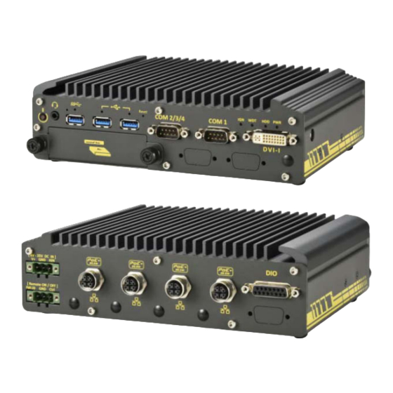
Page 37: Front Panel I/O
Nuvo-2610VTC Series Front Panel I/O NOTE Nuvo-2611VTC/ Nuvo-2612VTC share the same external mechanical design, while the Nuvo-2610VTC shares similar inputs/ outputs. A Nuvo-2611VTC/ Nuvo-2612VTC will be used for demonstration purposes. Item Description Power button Use this button to turn on or shutdown the system. - Page 38 Nuvo-2610VTC Series DVI-I offers both DVI and VGA signals. You can use the DVI-to-VGA adapter to connect a VGA display, or use Y-cable to DVI-I port have DVI/VGA dual display output. They support resolutions up to 1920 x 1080. Front-accessible 2.5” HDD tray (supports up to 15mm in height), please refer to the 2.5”...
-
Page 39: Power Button
Nuvo-2610VTC Series 2.4.1 Power Button The power button is a non-latched switch for ATX mode on/off operation. Press to turn on the system, PWR LED should light up and to turn off, you can either issue a shutdown command in the OS, or just press the power button. In case of system halts, you can press and hold the power button for 5 seconds to force-shutdown the system. -
Page 40: Cmos Reset Button
Nuvo-2610VTC Series 2.4.3 CMOS Reset Button The CMOS Reset button is used to manually reset the motherboard BIOS in case of system halt or malfunction. To avoid unexpected operation, it is purposely placed behind the panel. To reset, please use the tip of a pen, press and hold for at least 5 seconds to reset the BIOS. -
Page 41: Usb2.0 Port
Nuvo-2610VTC Series 2.4.5 USB2.0 Port The system offers two USB2.0 ports on its front panel with screw-lock mechanism (indicated in red). They are backward-compatible with USB 1.1 and USB 1.0 devices. Legacy USB support is also provided so you can use USB keyboard/mouse in DOS environment. -
Page 42: Com Ports (Com2/ Com3/ Com4)
Nuvo-2610VTC Series 2.4.7 COM Ports (COM2/ COM3/ COM4) Implemented using industrial-grade ITE8786 Super IO chip (-40 to 85°C) and provide up to 921600 bps baud rate, the second D-Sub male connector (COM2/ 3/ 4) can be configured in BIOS as single RS-422/ 485 port (COM2) or three 3-wire RS-232 ports (COM2/COM3/COM4). -
Page 43: Com 1 Port
Nuvo-2610VTC Series 2.4.8 COM 1 Port Isolated with up to 15kV ESD protection, the port is implemented using industrial-grade ITE8786 Super IO chip (-40 to 85°C) and provides up to 921600 bps baud rate.COM1 is aRS-485 port via 9-pin D-Sub male connector. The following table describes the pin definition of COM ports. -
Page 44: System Status Led
Nuvo-2610VTC Series 2.4.9 System Status LED There are four LED indicators on the I/O panel: PWR, WDT, HDD and IGN. The descriptions of these LEDs are listed in the following table. Indicator Color Description Yellow Ignition signal indicator, lid when IGN is high (12V/ 24V). -
Page 45: 2.4.10 Dvi-I Port
Nuvo-2610VTC Series 2.4.10 DVI-I Port The system features a DVI-I connector on its front panel that is also compatible with VGA signals. The DVI and VGA outputs are directly driven by integrated Intel HD graphics engine and support up to 1920 x 1080 resolution. -
Page 46: Rear Panel I/O
Nuvo-2610VTC Series Rear Panel I/O On the rear panel of the system, you will find a 3-pin terminal block for DC input with ignition power control, a power LED with remote on/ off control, four M12 X-coded connectors, and a 15-pin DIO port. -
Page 47: 3-Pin Terminal Block Dc Input/ Ignition Control
Nuvo-2610VTC Series 2.5.1 3-pin Terminal Block DC Input/ Ignition Control The system accepts a wide range of DC power input from 8 to 35V via a 3-pin pluggable terminal block, which is fit for field usage where DC power is usually provided. The screw clamping mechanism on the terminal block offers connection reliability when wiring DC power. -
Page 48: 3-Pin Remote On/ Off
Nuvo-2610VTC Series 2.5.2 3-pin Remote On/ Off The “Remote On/ Off” 3-pin connection allows for external switch extension. It is useful when the system is placed in a cabinet or a not easily accessed location. You may connect an external remote with an external status LED indicator (15mA) by connecting to PWR LED... -
Page 49: M12 X-Coded Poe Port
Nuvo-2610VTC Series 2.5.3 M12 X-coded PoE Port The system offers four PoE+ GbE ports via M12 X-coded connectors on the front panel. The ® ports are implemented using Intel I210 controller and the port indicated in green supports Wake-on-LAN. Power over Ethernet (PoE) supplies electrical power and data on a CAT-5/CAT-6 Ethernet cable. - Page 50 Nuvo-2610VTC Series Connector Pin Definition Panel side Cable connector end Signal M12 panel side M12 cable connector end Wire color LAN P0 LAN N0 LAN P1 LAN N1 LAN P3 LAN N3 LAN N2 LAN P2...
-
Page 51: Isolated Digital Input/ Output
Nuvo-2610VTC Series 2.5.4 Isolated Digital Input/ Output The system provides 4x isolated digital input channels and 4x isolated digital output channels. The DIO functions support polling mode I/O access and DI change-of-state interrupt. Please refer to Watchdog Timer & Isolated DIO for information on wiring and programming the isolated DIO channels. -
Page 52: Internal I/O Functions
Nuvo-2610VTC Series Internal I/O Functions In addition to I/O connectors on the front panel, the system also provides internal on-board expansion slots. In this section, we’ll illustrate these internal I/O functions. 2.6.1 M.2 2280 (SATA Signal Only) Slot for SSD The system has anM.2 2280 slot (SATA signal only) for you to install an M.2 SATA SSD for... - Page 53 Nuvo-2610VTC Series M.2 2280M Key Pin Definition Pin # Signal Pin # Signal +3V3 +3V3 +3V3 +3V3 +3V3 +3V3 SATA-B+ SATA-B- SATA-A- SATA-A+ Mechanical Key SUSCLK PEDET +3V3 +3V3 +3V3...
-
Page 54: Dram So-Dimm Slot
Nuvo-2610VTC Series 2.6.2 DRAM SO-DIMM Slot The system motherboard supports a SODIMM socket for installing a DDR4-3200 memory module up to 32GB capacity. -
Page 55: Mini-Pcie Slot (Usb2.0 Signal Only)
Nuvo-2610VTC Series 2.6.3 Mini-PCIe Slot (USB2.0 Signal Only) There is a full-size USB2.0 signal only mini-PCIe socket for better compatibility with off-the-shelf mini-PCIe wireless modules. For customers who want to install a mini-PCIe wireless module, please take advantage of the mini-PCIe socket and the antenna openings on the panels. - Page 56 Nuvo-2610VTC Series mini-PCIe Pin Definition Pin # Signal Pin # Signal +3.3Vaux +1.5V Mechanical Key W DISABLE# PERST# +3.3Vaux +1.5V Reserved Reserved USB D- USB D+ +3.3Vaux +3.3Vaux Reserved Reserved +1.5V Reserved Reserved +3.3Vaux...
-
Page 57: Mini-Pcie Slot (Pcie And Usb2.0 Signal)
Nuvo-2610VTC Series 2.6.4 Mini-PCIe Slot (PCIe and USB2.0 Signal) The mini-PCIe socket (in blue) accepts off-the-shelf mini-PCIe modules. You can add additional features to your system such as 5G/ 4G, WiFi, GPS, CAN bus, analog frame grabber, etc. The multiple antenna apertures can be located on the front and rear panel. - Page 58 Nuvo-2610VTC Series mini-PCIe Pin Definition Pin # Signal Pin # Signal +3.3Vaux +1.5V REFCLK- REFCLK+ Mechanical Key W_DISABLE# PERST# PERn0 +3.3Vaux PERp0 +1.5V SMB_CLK PETn0 SMB_DATA PETp0 USB_D- USB_D+ +3.3Vaux +3.3Vaux Reserved Reserved +1.5V Reserved Reserved +3.3Vaux WARNING Some off-the-shelf mini-PCIe 4G modules are not compliant to standard mini-PCIe interface.
-
Page 59: 3042/ 3052 B Key Socket
Nuvo-2610VTC Series 2.6.5 M.2 3042/ 3052 B Key Socket The system has one M.2 3042/ 3052 B key socket (in blue) for 5G/4G module installation and dual SIM slots (in red). The M.2 slot features USB3.1 and USB 2.0 signal. - Page 60 Nuvo-2610VTC Series M.2 3042/ 3052 B Key Pin Definition Pin # Signal Pin # Signal +3V3 +3V3 FULL_CARD_POWER_OFF_N USB_D+ W_DISABLE_N USB_D- Mechanical Key USB3.0-RX- USB3.0-RX+ UIM1-RESET UIM1-CLK USB3.0-TX- UIM1-DATA USB3.0-TX+ UIM1-PWR UIM2-DATA UIM2-CLK UIM2-RESET UIM2-PWR PERST_N +3V3 +3V3 +3V3...
-
Page 61: Ignition Rotary Switch
Nuvo-2610VTC Series 2.6.6 Ignition Rotary Switch The system features an ignition control switch that has multiple modes for pre and post ignition settings. Please refer to the section Ignition Power Control for details. -
Page 62: System Installation
Nuvo-2610VTC Series System Installation Before disassembling the system enclosure and installing components and modules, please make sure you have done the following: It is recommended that only qualified service personnel should install and service this product to avoid injury or damage to the system. -
Page 63: Disassembling The System
Nuvo-2610VTC Series Disassembling the System NOTE The enclosure difference Nuvo-2611VTC/ Nuvo-2612VTC to Nuvo-2610VTC is the addition Cassette module compartment at the bottom. To access system internal components, the system needs to be disassembled. To disassemble the system enclosure, please refer to the procedures below: Turn the system upside-down on a steady surface. - Page 64 Nuvo-2610VTC Series Gently wiggle the Cassette module and separate it from the enclosure. Remove the screw indicated on the rear I/O panel. Remove the screws (indicated in blue) and thumb screws (indicated in red) indicated on the front I/O panel, and remove the faceplate.
- Page 65 Nuvo-2610VTC Series Remove the screws from both sides of the chassis. Left side chassis screws Right side chassis screws Gently slide the bottom panel away from M12 panel (towards the panel with USB ports). Remove the U-shaped bottom panel to access internal expansion slots.
-
Page 66: Installing Internal Components
Nuvo-2610VTC Series Installing Internal Components 3.2.1 DDR4 SO-DIMM Installation There is a SO-DIMM memory slot on the motherboard that supports up to 32GB DDR4-3200. Please follow the procedures below to replace or install the memory modules. 1. Please refer to the section “Disassembling the... - Page 67 Nuvo-2610VTC Series 3. To install the memory module, insert gold fingers of the module into the slot at 45 degree angle, push down on the edge of the module and the clips on the side should clip the module into position.
-
Page 68: 2280 Ssd Installation
Nuvo-2610VTC Series 3.2.2 M.2 2280 SSD Installation The system has a SATA signal M.2 2280 slot for you to install an M.22280 SATA SSD. For installation, please refer to the following instructions. Please refer to the section “Disassembling the System”. - Page 69 Nuvo-2610VTC Series Insert the module on a 45 degree angle. Gently press down and secure the module with an M3 P-head screw. Reinstall the system enclosure or the bottom panel when done. If you need to install other components, please refer to respective sections.
-
Page 70: 3042/ 3052 B Key Installation
Nuvo-2610VTC Series 3.2.3 M.2 3042/ 3052 B Key Installation The system has an M.2 3042/ 3052 B key slot (indicated in blue)with two corresponding micro-SIM card slots (indicated in red). The M.2 slot can be accessed by removing the bottom panel. - Page 71 Nuvo-2610VTC Series To install the micro-SIM SIM card, slide the metallic cover in the direction shown and lift it to expose the socket and gold fingers. Slide cover in direction shown Lift the cover with fingertip Gently place the micro-SIM SIM card in the orientation shown, lower the cover and slide the cover in the direction shown to secure the SIM card in place.
- Page 72 Nuvo-2610VTC Series To install the M.2 3042/ 3052 module into place, insert the module on a 45° angle into the slot and secure it using the screw provided. Reinstall the system enclosureor the bottom panel when done. If you need to install other components, please refer to respective sections.
-
Page 73: Minipice Installation
Nuvo-2610VTC Series 3.2.4 miniPICe Installation The system has two miniPCIe sockets, one offers both PCIe and USB2.0 signals (indicated in red), while the other offers only USB2.0 signal (indicated in blue) for WiFi module installation. The mini PCIe slots can be accessed by removing the bottom panel. Please refer to the section “Disassembling the... - Page 74 Nuvo-2610VTC Series To install the antenna onto the system enclosure, clip on the IPEZ-to-SMA cable to the module and secure the antenna to the side panel (refer to the module’s manual for clip-on connection). Clip on the IPEZ-to-SMA cable Secure the connector body, coupling nut...
-
Page 75: Installing The System Enclosure
Nuvo-2610VTC Series Installing the System Enclosure To install the enclosure, please follow the instructions below. Please make sure heatsinks for DRAM/ M.2 2280 slot and M.2 3042/ 3052 slot are installed (secured with screws indicated) regardless if a module is installed into the slot. - Page 76 Nuvo-2610VTC Series Secure it with two screws on both sides. Left side chassis screws Right side chassis screws Place and secure the USB panel with screws (indicated in blue), and insert the 2.5” tray and secure it by tightening the thumb screws (indicated in red).
- Page 77 Nuvo-2610VTC Series Turn the system upside-down, place the Cassette module onto the enclosure while ensuring the gold fingers are properly inserted. Secure the Cassette module with the screws indicated.
-
Page 78: Hard Drive/ Ssd Installation
Nuvo-2610VTC Series 2.5” Hard Drive/ SSD Installation To install a 2.5” HDD or SSD in the front accessible tray, please refer to the procedure below. Place the system on a flat sturdy surface, and turn the thumb screws indicated anti-clockwise. - Page 79 Nuvo-2610VTC Series Gently insert the tray back into the slot until you feel resistance, and secure the tray by tightening the thumb screws clockwise to complete the installation.
-
Page 80: Pcie Add-On Card Installation (Nuvo-2612Vtc Only)
Nuvo-2610VTC Series PCIe Add-on Card Installation (Nuvo-2612VTC Only) The Nuvo-2612VTC comes with a Cassette module for you to install a PCIe add-on card to add additional connectivity or functionality. To install, please refer to the following instructions. Place the system on a flat sturdy surface and turn the system upside-down. Remove the four screws indicated. - Page 81 Nuvo-2610VTC Series Remove the screw indicated and gently lift and separate the L-shaped panel from the Cassette module.
- Page 82 Nuvo-2610VTC Series Before installing the PCI/ PCIe card into the Cassette module, it is recommended to attach the rubber spacers provided onto the back of the card to avoid possible contact with the enclosure. Simply attach the rubber spacers on the back of the card, in the four corners.
- Page 83 Nuvo-2610VTC Series Lower the add-on card you wish to install into the Cassette module, make sure the PCIe gold fingers is properly inserted (indicated in red), the bottom of the bezel is properly engaged, and the bezel is secured with a screw.
- Page 84 Nuvo-2610VTC Series Gently lower the Cassette module back onto the system enclosure while ensuring the gold fingers are properly inserted. Secure the screws indicated to complete the installation.
-
Page 85: Damping Bracket For Nuvo-2610Vtc Series
Nuvo-2610VTC Series Damping Bracket for Nuvo-2610VTC Series Neousys provides a damping bracket as a standard accessory for Nuvo-2610VTC systems. The damping bracket is ideal for use in in-vehicle deployments. To install the damping bracket onto Nuvo-2610VTC, please refer to the instructions listed below. - Page 86 Nuvo-2610VTC Series Take the damping bracket out of the accessory box, insert four anti-vibration grommets into the location shown on the bracket, and secure the bracket onto the bottom of the enclosure using four screws. Referring to the illustration shown above, insert four...
-
Page 87: Damping Bracket Installation For Nuvo-2611Vtc/ Nuvo-2612Vtc
Nuvo-2610VTC Series Damping Bracket Installation for Nuvo-2611VTC/ Nuvo-2612VTC Place the system on a flat sturdy surface and turn the system upside-down. Remove the four screws and rubber standoffs (if installed) indicated. NOTE Please not that the screw location indicated in... - Page 88 Nuvo-2610VTC Series Take the damping bracket out of the accessory box, insert four anti-vibration grommets into the location shown on the bracket, and secure the bracket onto the bottom of the enclosure using four screws. Referring to the illustration shown above, insert four...
-
Page 89: Wall Mount Bracket For Nuvo-2610Vtc Series (Optional)
Nuvo-2610VTC Series Wall Mount Bracket for Nuvo-2610VTC Series (Optional) Neousys provides versatile mounting methods for Nuvo-2610VTC systems. You can use the optional wall-mount brackets to mount the system onto the wall. To install the wall-mount bracket, please refer to the instructions listed below. - Page 90 Nuvo-2610VTC Series Take the two wall-mount brackets and four M4 screws out of the accessory box, secure the wall mount brackets onto the bottom of the enclosure according to the illustration shown below. Place the system on a flat surface portion of the wall and secure it with four (4) M4 pan screws.
-
Page 91: Wall-Mount Bracket For Nuvo-2611Vtc/ Nuvo-2612Vtc
Nuvo-2610VTC Series 3.8.2 Wall-mount Bracket for Nuvo-2611VTC/ Nuvo-2612VTC Place the system on a flat sturdy surface and turn the system upside-down. Remove the four screws and rubber standoffs indicated. - Page 92 Nuvo-2610VTC Series Take the two wall-mount brackets and four M4 screws out of the accessory box, secure the wall mount brackets onto the bottom of the enclosure according to the illustration shown below. Place the system on a flat surface portion of the wall and secure it with four (4) M4 pan screws.
-
Page 93: Powering On The System
Nuvo-2610VTC Series Powering On the System There are three methods to power on the system Pressing the power button Sending a LAN packet via Ethernet (Wake-on-LAN) Powering on via ignition control (for Nuvo-2610DS-IGN only, please refer to... - Page 94 Nuvo-2610VTC Series NOTE Please make sure the Intel chipset and Ethernet driver has been properly installed prior to setting up WOL function. To enable WOL function, please set up WOL settings in the BIOS and in the operating system by follow the steps described below.
- Page 95 Nuvo-2610VTC Series frame containing anywhere within its payload 6 bytes of all 255 (FF FF FF FF FF FF in hexadecimal), followed by sixteen repetitions of the target computer's 48-bit MAC address. For example, NIC’s 48-bit MAC Address is 78h D0h 04h 0Ah 0Bh 0Ch...
-
Page 96: 3.10 Ignition Power Control
Nuvo-2610VTC Series 3.10 Ignition Power Control The ignition power control module for in-vehicle applications is a MCU-based implementation that monitors the ignition signal and reacts to turn on/off the system according to predefined on/off delay. Its built-in algorithm supports other features such as ultra-low power standby, battery-low protection, system hard-off, etc. -
Page 97: 3.10.2 Additional Features Of Ignition Power Control
Nuvo-2610VTC Series 3.10.2 Additional Features of Ignition Power Control In addition to the typical timing correlation, the ignition power control module offers additional features to provide additional reliability for in-vehicle applications. 1. Low battery detection The ignition power control module continuously monitors the voltage of DC input when the system is operational. -
Page 98: 3.10.3 Wiring Ignition Signal
Nuvo-2610VTC Series 3.10.3 Wiring Ignition Signal To have ignition power control for in-vehicle usage, you need to supply IGN signal to the system. The IGN input is located on the 3-pin pluggable terminal block (shared with DC power input). Below is the typical wiring configuration for in-vehicle applications. -
Page 99: 3.10.4 Configure Your Windows System
Nuvo-2610VTC Series 3.10.4 Configure your Windows system When applying ignition power control to your system, please make sure you’ve configured your Windows system to initiate a shutdown process when pressing the power button. By default, Windows 10 goes to sleep (S3) mode when power button is pressed. As sleep (S3) -
Page 100: 3.10.5 Operation Modes Of Ignition Power Control
Nuvo-2610VTC Series 3.10.5 Operation Modes of Ignition Power Control You can use the rotary switch to configure the operation mode. The system offers 16 (0~15) operation modes with different power-on/power-off delay configurations. The ignition control rotary switch can be located on the motherboard. Please refer to the “Disassembling the enclosure”... - Page 101 Nuvo-2610VTC Series Mode 3 ~ Mode 12 Mode 3 ~ Mode 12 have various power-on delay and power-off delay. Each mode supports a hard-off timeout of 10 minutes. Mode Power-on Delay Power-off Delay Hard-off Timeout 10 seconds 10 seconds...
- Page 102 Nuvo-2610VTC Series Mode 15 (F) The ignition control module is implemented to support BIOS-configurable ignition parameters. When the rotary switch is set to 15 (0xF), users can configure ignition parameters in BIOS setup menu. To configure ignition parameters in BIOS, please follow the steps below.
- Page 103 Nuvo-2610VTC Series [IGN Operation Mode] ATX mode without power-on and power-off delay. Same operation as rotary switch set to 0. Automatically turns on the system when DC power is applied. AUTO-ON Same operation as rotary switch set to 1. Ignition power control mode. Ignition control is executed...
- Page 104 Nuvo-2610VTC Series [Smart Off-Delay] If system is manually shutdown during the power-off delay Enabled period, ignition control module will cut off system power in prior to expiration of power-off delay to save battery power. Ignition control module cut off system power only after Disabled power-off delay expired.
- Page 105 Nuvo-2610VTC Series [BIOS POST Check] This option secures a boot-to-OS operation. If the system is failed to boot to OS (e.g. disk failure or no bootable device) Enabled within 60 seconds, ignition control module will cut off system power and retry another power on cycle.
- Page 106 Nuvo-2610VTC Series [Power On Delay] Specifies the power-on delay duration. Once IGN signal goes active and sustains for the duration of power-on delay, ignition control module turns on system power and boot up the system.
- Page 107 Nuvo-2610VTC Series [Power Off Delay] Specifies the power-off delay duration. Once IGN signal goes inactive and sustains for the duration of power-off delay, ignition control module performs system shutdown (soft-off) and then cut off system power.
- Page 108 Nuvo-2610VTC Series [Hard-off Timeout] Specifies system hard-off timeout. Once system failed to normally shutdown via a soft-off operation due to system/application halts (e.g. Windows BSOD), ignition control module can compulsively cut off system power after the given hard-off timeout.
- Page 109 Nuvo-2610VTC Series [Battery Voltage] Specifies the battery voltage of the vehicle where System VTC is deployed. Typically it’s 12 VDC for sedan and 24 VDC for bus/truck.
- Page 110 Nuvo-2610VTC Series [Low Battery Threshold] When system is running, ignition control module continuously monitors the battery voltage. Once the battery voltage is lower than the specified threshold, it performs system shutdown (soft-off) and cut off system power to prevent battery drain-out. You should specify the low battery threshold according to the given battery voltage.
-
Page 111: System Configuration
Nuvo-2610VTC Series System Configuration 4.1 BIOS Settings The system is shipped with factory-default BIOS settings meticulously programmed for optimum performance and compatibility. In this section, we’ll illustrate some of BIOS settings you may need to modify. Please always make sure you understand the effect of change before you proceed with any modification. -
Page 112: Com 1Portconfiguration
Nuvo-2610VTC Series 4.1.1 COM 1PortConfiguration The system’s COM 1 port is a RS-485 port. You can enable/ disable both COM ports via BIOS settings. To set COM port operating mode: Press F2when the system boots up to enter the BIOS setup utility. -
Page 113: Com 2/ 3/ 4 Ports
Nuvo-2610VTC Series 4.1.2 COM 2/ 3/ 4 Ports The system’s COM2 port can act as a 3x 3-wire RS-232 port (being COM ports 2/ 3/ 4), or it can act as a RS-422/ 485 (being a COM2 port). You can configure the COM ports via BIOS settings. -
Page 114: Com Port High Speed Mode
Nuvo-2610VTC Series 4.1.3 COM Port High Speed Mode The high speed mode of each COM port effectively allows for the port's baud rate generator to operate at 8x the speed with an effective baud rate of 921,600 bps (115,200 x 8). Please refer to the following instructions on how to enable the high speed mode for your COM port (COM1 used as an example). -
Page 115: Power On After Power Failure Option
Nuvo-2610VTC Series 4.1.4 Power On After Power Failure Option This option defines the behavior of system when DC power is supplied. Value Description S0 – Power On System is powered on when DC power is supplied. S5 – Power Off System is kept in off state when DC power is supplied. -
Page 116: Wake On Lan Option
Nuvo-2610VTC Series 4.1.5 Wake on LAN Option Wake-on-LAN (WOL) is a mechanism which allows you to turn on your system via Ethernet connection. To utilize Wake-on-LAN function, you have to enable this option first in BIOS settings. Please refer to “Powering On Using Wake-on-LAN”to set up the system. -
Page 117: Add Boot Options
Nuvo-2610VTC Series 4.1.6 Add Boot Options The Add Boot Options dedicates the boot sequence order of a newly added device (eg. USB flash drive). The setting allows you to set the newly added device to boot first or as the last device on the list. -
Page 118: Watchdog Timer For Booting
Nuvo-2610VTC Series 4.1.7 Watchdog Timer for Booting The Watchdog timer setting in the BIOS ensures a successful system boot by specifying a timeout value. If the Watchdog timer is not stopped and expires, the BIOS will issues a reset command to initiate another boot process. There are two options in BIOS menu, “Automatically after POST”... -
Page 119: Os Support And Driver Installation
Due to Intel’s policy, the system only provides driver support for Windows 10 64-bit. For Linux support, please use Linux kernel versions no later than 5.8. The following list contains the operating systems which have been tested in Neousys Technology Inc. Microsoft Windows10Professional 64-bit Microsoft Windows 10 IoT Enterprise 64-bit Ubuntu 20.04.2 LTS** (5.8 kernel) -
Page 120: Appendix A Using Wdt & Dio
In this section, we’ll illustrate how to use the function library provided by Neousys to program the WDT functions. Currently, WDT driver library supports Windows 10 32-bit and 64-bit versions. For other OS support, please contact Neousys Technology for further information. Installing WDT_DIO Library The WDT_DIO function library is delivered in the form of a setup package named WDT_DIO_Setup.exe. -
Page 121: Wdt And Dio Library Installation
Nuvo-2610VTC Series WDT and DIO Library Installation To setup WDT & DIO Library, please follow instructions below. 1. Execute WDT_DIO_Setup.2.3.1.8.exe (or later) and the following dialog appears. 2. Click “Next >” and specify the directory of installing related files. The default directory is... - Page 122 Nuvo-2610VTC Series 3. Once the installation has finished, a dialog will appear to prompt you to reboot the system. The WDT & DIO library will take effect after the system has rebooted. 4. When programming your WDT or DIO program, the related files are located in...
-
Page 123: Wdt Functions
Nuvo-2610VTC Series WDT Functions InitWDT BOOL InitWDT(void); Syntax Description: Initialize the WDT function. You should always invoke InitWDT() before set or start watchdog timer. None Parameter Return Value TRUE: Successfully initialized FALSE: Failed to initialize BOOL bRet = InitWDT() Usage... -
Page 124: Startwdt
Nuvo-2610VTC Series StartWDT Syntax BOOL StartWDT(void); Description Starts WDT countdown. Once started, the WDT LED indicator will begin blinking. If ResetWDT() or StopWDT is not invoked before WDT countdowns to 0, the WDT expires and the system resets. Parameter None... -
Page 125: Dio Functions
Nuvo-2610VTC Series DIO Functions InitDIO Syntax BOOL InitDIO(void); Initialize the DIO function. You should always invoke InitDIO() Description before write/read anyDIO port/channel. Parameter None Return Value Returns TRUE if initialization successes, FALSE if initialization failed. Usage BOOL bRet = InitWDT() -
Page 126: Dowriteline
Nuvo-2610VTC Series DOWriteLine Syntax void DOWriteLine(BYTE ch, BOOL value); Write a single channel of isolated digital output. Description Parameter BYTE value specifies the DO channel to be written. Ch should be a value of 0 ~ 7. value BOOL value (TRUE or FALSE) specifies the status of DO channel. -
Page 127: Appendix B Poe On/ Off Control
Appendix AWatchdog Timer & Isolated DIO for installation before programming PoE on/off control function. NOTE Nuvo-2610VTC series will be shown in illustrations for demonstration purposes. GetStatusPoEPort Syntax BYTE GetStatusPoEPort (Byte port); Description Get current on/off status of designated PoE port. -
Page 128: Enablepoeport
Nuvo-2610VTC Series EnablePoEPort Syntax BOOL EnablePoEPort (BYTE port); Turn on PoE power of designated PoE port. Description Parameter port BYTE value specifies the index of PoE port. Please refer to the following illustration, port should be a value of 1 ~ 4... -
Page 129: Disablepoeport
Nuvo-2610VTC Series DisablePoEPort Syntax BOOL DisablePoEPort (BYTE port); Description Turn off PoE power of designated PoE port Parameter port BYTE value specifies the index of PoE port. Please refer to the following illustration, port should be a value of 1 ~ 4...
Need help?
Do you have a question about the Nuvo-2610VTC Series and is the answer not in the manual?
Questions and answers