Table of Contents
Advertisement
Quick Links
Advertisement
Table of Contents

Related Manuals for Neousys Technology Nuvo-6000 Series


Summary of Contents for Neousys Technology Nuvo-6000 Series
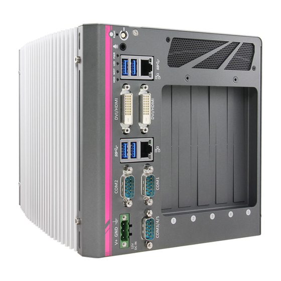
- Page 1 Neousys Technology Inc. Nuvo-6000 Series Intel® 6th-Gen Skylake Core™ i7/i5 Fanless Box-PC with Multiple PCIe/PCI Expansion Slots Nuvo-6032 / Nuvo-6002 User’s Manual Rev. A3 Published Sep. 2020 Copyright © 2016 Neousys Technology Inc. All Right Reserved. Page 1 of 100...
-
Page 2: Table Of Contents
2.3.9 PCI Express Slots ..................28 2.3.10 PCI Slots (Nuvo-6032 Only) ..............29 2.4 Mechanical Dimension ..................30 2.4.1 Front View of Nuvo-6032 ................30 2.4.2 Back View of Nuvo-6032 ................31 Copyright © 2016 Neousys Technology Inc. All Right Reserved. Page 2 of 100... - Page 3 3.10.2 Power on Nuvo-6000 Using Wake-on-LAN Function ........ 70 Chapter 4 BIOS and Driver ....................73 4.1 BIOS Settings ....................... 73 4.1.1 COM1 & COM2 Operating Mode ..............73 Copyright © 2016 Neousys Technology Inc. All Right Reserved. Page 3 of 100...
-
Page 4: Manual Revision History
Ethernet LED status description update Status LED & Remote On/ Off pin update USB port signal update Sep. 2019 Status LED & Remote On/ Off pin update Copyright © 2016 Neousys Technology Inc. All Right Reserved. Page 4 of 100... -
Page 5: Declaimer
This manual is intended to be used as a practical and informative guide only and is subject to change without prior notice. It does not represent commitment from Neousys Technology Inc. Neousys shall not be liable for direct, indirect, special, incidental, or consequential damages arising out of the use of the product or documentation, nor for any infringements upon the rights of third parties, which may result from such use. -
Page 6: Chapter 1 Introduction
Chapter 1 Introduction 1.1 Overview. Nuvo-6000 series is the perfect replacement of your bulky rack-mount or wall-mount IPC systems. Leveraging 6th-Gen Intel® Skylake platform, It delivers the same computing power as traditional IPCs, but in a more compact form-factor and fanless operation. -
Page 7: Product Specification
1x full-size mSATA socket Power Supply DC Input 1x 3-pin pluggable terminal block for 8~35 VDC input With i7-6700TE: 48.52W@24VDC Power Consumption With i5-6500TE: 44.38W@24VDC With i3-6100TE: 34.83W@24VDC Copyright © 2016 Neousys Technology Inc. All Right Reserved. Page 7 of 100... - Page 8 * The high operating temperature specified here is defined under the condition of 100% CPU loading applied using Passmark® BurnInTest 8.0. For detail testing criteria, please contact Neousys Technology ** For sub-zero operating temperature, a wide temperature HDD drive or Solid State Disk (SSD) is required.
-
Page 9: Specification Of Nuvo-6002
With i3-6100TE: 34.83W@24VDC Mechanical Dimension 124 mm (W) x 225 mm (D) x 174 mm (H) Weight 2.8 kg (with one 2.5” HDD and DDR4 memory module) Copyright © 2016 Neousys Technology Inc. All Right Reserved. Page 9 of 100... - Page 10 * The high operating temperature specified here is defined under the condition of 100% CPU loading applied using Passmark® BurnInTest 8.0. For detail testing criteria, please contact Neousys Technology ** For sub-zero operating temperature, a wide temperature HDD drive or Solid State Disk (SSD) is required.
-
Page 11: Chapter 2 Getting To Know Your Nuvo-6000
Getting to know your Nuvo-6000 2.1 Unpacking your Nuvo-6000 When you receive the package of Nuvo-6000 series, please check immediately if the package contains all the items listed in the following table. If any item is missing or damaged, please contact your local dealer or Neousys Technology Inc. for further assistance. -
Page 12: Front Panel I/O Functions
To avoid unexpected operation, the reset button is hidden behind the front panel. You need to use a pin-like object to push the reset button. Copyright © 2016 Neousys Technology Inc. All Right Reserved. Page 12 of 100... -
Page 13: Speaker-Out Jack
Green Reserved for future usage. Yellow Watchdog timer indicator, flashing when watchdog timer is started. Hard drive indicator, flashing when SATA HDD is active. Copyright © 2016 Neousys Technology Inc. All Right Reserved. Page 13 of 100... -
Page 14: Usb 3.0 Connectors
Please refer to Appendix A for information of installing Windows 7 on Nuvo-6000 series. 2.2.6 Gigabit Ethernet Port Nuvo-6000 series offers 2 GbE ports on its front panel. The ® GbE port marked in blue is implemented with Intel I219-LM ®... -
Page 15: Dvi-D Connector
GbE controller. Please refer to section 4.3 for information of driver installation. 2.2.7 DVI-D Connector Nuvo-6000 series has two DVI-D connectors on its front panel to support dual independent display outputs. DVI/HDMI transmits graphics data in digital format and therefore can deliver better image quality at high resolution. -
Page 16: Com Ports (Com1/Com2)
COM ports. COM1 & COM2 RS-485 Mode Pin# RS-232 Mode RS-422 Mode (Two-wire 485) 422 TXD+ 485 TXD+/RXD+ 422 RXD+ 422 RXD- 422 TXD- 485 TXD-/RXD- Copyright © 2016 Neousys Technology Inc. All Right Reserved. Page 16 of 100... -
Page 17: Com Ports (Com3/Com4/Com5)
The following table describes the pin definition of the DB9 connector as well as the Y-cable. COM3/4/5 DB9 Y-Cable DB9 Pin# COM3 COM4 COM5 COM3 (A) Pin# COM4 (B) COM5 (C) Copyright © 2016 Neousys Technology Inc. All Right Reserved. Page 17 of 100... -
Page 18: 3-Pin Terminal Block For Dc Input
Nuvo-6000 Series User’s Manual 2.2.10 3-Pin Terminal Block for DC Input Nuvo-6000 series allows a wide range of DC power input from 8 to 35V via a 3-pin pluggable terminal block, which is fit for field usage where DC power is usually provided. And the screw clamping connection of the terminal block gives a very reliable way of wiring DC power. -
Page 19: Internal I/O Functions
The following table describes the pin definition of the status LED output. Copyright © 2016 Neousys Technology Inc. All Right Reserved. Page 19 of 100... - Page 20 (polarity is negligible). Ctrl+ Un-used pin Note Please make sure the polarity is correct when you connect the external LED indicator to the Status LED Output. Copyright © 2016 Neousys Technology Inc. All Right Reserved. Page 20 of 100...
-
Page 21: Ddr4 Sodimm Socket
Nuvo-6000 Series User’s Manual 2.3.2 DDR4 SODIMM Socket Nuvo-6000 series provides one 260-pin, SODIMM socket for installing DDR4 memory module. It supports maximal 16GB capacity by installing one 16GB DDR4 2133 MHz SODIMM modules. For information of installing DDR4 memory modules, please refer to section 3.3 for details. -
Page 22: Internal Usb2.0 Pin Header
USB cable. Please contact Neousys for further information. Pin# Pin Definition USB 5V Power, Max 500mA USB 5V Power, Max 500mA USB6 D- USB7 D- USB6 D+ USB7 D+ Ground Ground 9 ~ 16 Copyright © 2016 Neousys Technology Inc. All Right Reserved. Page 22 of 100... -
Page 23: Msata Socket
The system recognizes mSATA as a native storage device and accordingly you can install any operating system in the mSATA module, such as Windows 7, Windows 8, Windows 10, Linux and etc. Copyright © 2016 Neousys Technology Inc. All Right Reserved. Page 23 of 100... -
Page 24: Sata #1 Port
2.5” HDD/SSD to this port using the HDD bracket shipped with Nuvo-6000. For information of installing HDD/SSD to the SATA port #1, please refer to section 3.5.1 for detail. Copyright © 2016 Neousys Technology Inc. All Right Reserved. Page 24 of 100... -
Page 25: Sata #2 And Sata #3 Ports (Nuvo-6032 Only)
HDD tray shipped with Nuvo-6032 for the installation of 2.5” HDD/SSD. For information of installing HDD/SSD to the SATA port #2 and port #3, please refer to section 3.5.2 for detail. Copyright © 2016 Neousys Technology Inc. All Right Reserved. Page 25 of 100... -
Page 26: Vdc Pcie Power Connector
8A rated current. This can be useful if you want to power a PCI Express graphics card with up to 90W TDP. Pin# Pin Definition 12 VDC 12 VDC 12 VDC Copyright © 2016 Neousys Technology Inc. All Right Reserved. Page 26 of 100... -
Page 27: Internal Usb Port
In additional the USB header connector on the SBC, Nuvo-6000 offers another USB 2.0 Type-A port on the backplane. You can utilize this USB port to connect a USB protection dongle inside the chassis of Nuvo-6000 controller. Copyright © 2016 Neousys Technology Inc. All Right Reserved. Page 27 of 100... -
Page 28: Pci Express Slots
The operating temperature of the whole system when cards installed is affected by the power consumption and operating temperature of add-on cards. Please consult your add-on card dealer or Neousys Technology for further information. Copyright © 2016 Neousys Technology Inc. All Right Reserved. Page 28 of 100... -
Page 29: Pci Slots (Nuvo-6032 Only)
The operating temperature of the whole system when cards installed is affected by the power consumption and operating temperature of add-on cards. Please consult your add-on card dealer or Neousys Technology for further information. Copyright © 2016 Neousys Technology Inc. All Right Reserved. Page 29 of 100... -
Page 30: Mechanical Dimension
Nuvo-6000 Series User’s Manual 2.4 Mechanical Dimension 2.4.1 Front View of Nuvo-6032 Copyright © 2016 Neousys Technology Inc. All Right Reserved. Page 30 of 100... -
Page 31: Back View Of Nuvo-6032
Nuvo-6000 Series User’s Manual 2.4.2 Back View of Nuvo-6032 Copyright © 2016 Neousys Technology Inc. All Right Reserved. Page 31 of 100... -
Page 32: Top View Of Nuvo-6032
Nuvo-6000 Series User’s Manual 2.4.3 Top View of Nuvo-6032 Copyright © 2016 Neousys Technology Inc. All Right Reserved. Page 32 of 100... -
Page 33: Bottom View Of Nuvo-6032
Nuvo-6000 Series User’s Manual 2.4.4 Bottom View of Nuvo-6032 Copyright © 2016 Neousys Technology Inc. All Right Reserved. Page 33 of 100... -
Page 34: Right View Of Nuvo-6032
Nuvo-6000 Series User’s Manual 2.4.5 Right View of Nuvo-6032 2.4.6 Left View of Nuvo-6032 Copyright © 2016 Neousys Technology Inc. All Right Reserved. Page 34 of 100... -
Page 35: Front View Of Nuvo-6002
Nuvo-6000 Series User’s Manual 2.4.7 Front View of Nuvo-6002 Copyright © 2016 Neousys Technology Inc. All Right Reserved. Page 35 of 100... -
Page 36: Back View Of Nuvo-6002
Nuvo-6000 Series User’s Manual 2.4.8 Back View of Nuvo-6002 Copyright © 2016 Neousys Technology Inc. All Right Reserved. Page 36 of 100... -
Page 37: Top View Of Nuvo-6002
Nuvo-6000 Series User’s Manual 2.4.9 Top View of Nuvo-6002 Copyright © 2016 Neousys Technology Inc. All Right Reserved. Page 37 of 100... -
Page 38: Bottom View Of Nuvo-6002
Nuvo-6000 Series User’s Manual 2.4.10 Bottom View of Nuvo-6002 Copyright © 2016 Neousys Technology Inc. All Right Reserved. Page 38 of 100... -
Page 39: Right View Of Nuvo-6002
Nuvo-6000 Series User’s Manual 2.4.11 Right View of Nuvo-6002 2.4.12 Left View of Nuvo-6002 Copyright © 2016 Neousys Technology Inc. All Right Reserved. Page 39 of 100... -
Page 40: Chapter 3 Getting Start
Chapter 3 Getting Start 3.1 Dissemble your Nuvo-6000 Controller In prior to install components such as CPU, memory and HDD to Nuvo-6000 series, you need to disassemble Nuvo-6000 controller and access the PCBA. Please cautiously follow the procedures described here to prevent any damage on your Nuvo-6000 controller. -
Page 41: Disassemble The Sbc Of Nuvo-6000
Loose four M3, P-head screws on the backplane and pull it toward the direction of arrow to remove the backplane. Remove two hex screws near COM3/4/5 connector. Copyright © 2016 Neousys Technology Inc. All Right Reserved. Page 41 of 100... - Page 42 Remove four hex bolts used to fix heat-sink and chassis. Pull the heat-sink/SBC assembly slightly backward and lift it up to separate it from the chassis. Now you can separate the heat-sink/SBC assembly from the chassis. Copyright © 2016 Neousys Technology Inc. All Right Reserved. Page 42 of 100...
-
Page 43: Install And Replace A Lga1151 Cpu
Follow instructions described in section 3.1.2 to disassemble the heat-sink/SBC assembly from Nuvo-6000 chassis. Place the heat-sink/SBC assembly on a flat surface. Remove the SBC from the heat-sink by loosing four M3 P-head. Copyright © 2016 Neousys Technology Inc. All Right Reserved. Page 43 of 100... - Page 44 Place the PCBA on a flat surface. Remove the plastic protective cover from the LGA1151 socket. Caution When the protective cover is removed and LGA1151 socket is exposed, please carefully handle the PCBA to avoid any damage on LGA socket. Copyright © 2016 Neousys Technology Inc. All Right Reserved. Page 44 of 100...
- Page 45 The CPU retaining bracket must be screwed from the opposite side. Please hold the CPU and bracket firmly while turning the PCBA upside down, and secure the CPU retaining bracket with two M3 P-head screws. Copyright © 2016 Neousys Technology Inc. All Right Reserved. Page 45 of 100...
- Page 46 Get five M3 spring screws from the accessory box. Fix them according to the order indicated on the photo (yellow circles). And tighten four M3 P-head screws (red circles) to fix the PCBA to the heat-sink. Copyright © 2016 Neousys Technology Inc. All Right Reserved. Page 46 of 100...
-
Page 47: Replace The Cpu On Nuvo-6000
M3 spring screws (yellow circles) and six M3 P-head (red circles). Gently lift the SBC from the heat-sink. The CPU and CPU retaining bracket shall stay with the heat-sink. Copyright © 2016 Neousys Technology Inc. All Right Reserved. Page 47 of 100... - Page 48 Insert a slotted screwdriver into the gap between the CPU retaining bracket and the heat-sink, and lever the CPU bracket. Please DO NOT apply force to the CPU directly otherwise the CPU can be damage. Copyright © 2016 Neousys Technology Inc. All Right Reserved. Page 48 of 100...
- Page 49 CPU. If it’s broken, please replace it with a new one. Follow steps described in step 5 to step 9 in section 3.2.1 to install a new CPU to your Nuvo-6000 controller. Copyright © 2016 Neousys Technology Inc. All Right Reserved. Page 49 of 100...
-
Page 50: Install Ddr4 Sodimm Module
Nuvo-6000 Series User’s Manual 3.3 Install DDR4 SODIMM Module Nuvo-6000 series provides one 260-pin, SODIMM socket for installing DDR4 memory module. It supports maximal 16GB capacity by installing one 16 GB DDR4-2133 SODIMM modules. You can install/replace DDR4 SODIMM modules by following the steps described in this section. -
Page 51: Install Msata Ssd
Nuvo-6000 Series User’s Manual 3.4 Install mSATA SSD Nuvo-6000 series provides a full-size mSATA socket for installing mSATA SSD. In this section, we demonstrate how to install a mSATA SSD on the Nuvo-6000 controller. Follow instructions described in section 3.1.1 to remove the chassis cover. You can see the mSATA socket on the SBC exposed. -
Page 52: Install 2.5" Hdd/Ssd
SATA port #1 on the SBC. Get the HDD bracket from the accessory box and fix the HDD to the bracket using four M3, F-head screws. Copyright © 2016 Neousys Technology Inc. All Right Reserved. Page 52 of 100... -
Page 53: Install 2.5" Hdd/Ssd To Sata Port #2 & #3 (Nuvo-6032 Only)
Get the HDD tray from the accessory box. Place 2.5” SATA HDD/SSD on the top of HDD tray. Fix them from the opposite side using eight M3, F-head screws. Copyright © 2016 Neousys Technology Inc. All Right Reserved. Page 53 of 100... - Page 54 Align the HDD tray with guided nuts on the bottom of chassis and slide it into the chassis till SATA HDD drives are firmly attached to the connectors on SBC. Secure the HDD/tray assembly to the chassis using two M3, F-head screws. Copyright © 2016 Neousys Technology Inc. All Right Reserved. Page 54 of 100...
-
Page 55: Install Pci/Pcie Add-On Card
Nuvo-6000 Series User’s Manual 3.6 Install PCI/PCIe Add-on Card Nuvo-6000 series provides PCI and PCIe slots on its backplane. Nuvo-6032 provides one x16 PCIe slot, one x8 slot and three 5V, 33MHz/32-bit PCI slots, as Nuvo-6002 provides one x16 PCIe slot and one x8 PCIe slot. The maximum allowable length of a add-on card to be installed into Nuvo-6000 is varied depending on whether the optional fan is installed. - Page 56 Nuvo-6000 Series User’s Manual Fix the PCI/PCIe add-on card using the M3, PW-head screw. Copyright © 2016 Neousys Technology Inc. All Right Reserved. Page 56 of 100...
-
Page 57: Install Optional Fan
To install the optional fan, please follow the steps listed below. Follow instructions described in section 3.1.1 to remove the chassis cover. Remove pre-cutting plates for fan apertures on the back of chassis. Copyright © 2016 Neousys Technology Inc. All Right Reserved. Page 57 of 100... - Page 58 And plug the power connector of fan into the fan power receptacle on the backplane. Fix the fan from outside using four F-head screws. Copyright © 2016 Neousys Technology Inc. All Right Reserved. Page 58 of 100...
-
Page 59: Mount Your Nuvo-6000
Fix Nuvo-6032 on the wall via the screw holes of the mounting bracket. You can also take advantage of the keyhole-shaped holes of the mounting bracket to suspend Nuvo-6032 on the Wall. Copyright © 2016 Neousys Technology Inc. All Right Reserved. Page 59 of 100... -
Page 60: Mount Your Nuvo-6032 On A Flat Surface
Get two wall-mounting brackets and four M4 screws from the accessory box. Fix the mounting brackets to the bottom side of Nuvo-6032 using M4 screws. Fix Nuvo-6032 on a flat surface via the screw holes of two mounting brackets. Copyright © 2016 Neousys Technology Inc. All Right Reserved. Page 60 of 100... -
Page 61: Mount Your Nuvo-6032 On The Din Rail
Nuvo-6032 using four M4 screws before mount it to a DIN rail. This option can be useful if you want to deploy Nuvo-6032 inside an equipment cabinet where DIN rail is available. Copyright © 2016 Neousys Technology Inc. All Right Reserved. Page 61 of 100... -
Page 62: Mount Your Nuvo-6032 Into A Rack
1. Apply 10x M4 flat-head screws to fix the side plates to the bottom plate as the illustration below. Side Plate Bottom Plate Side Plate 2. Please Nuvo-6032 upside down on a flat surface and remove four foot pads on the Copyright © 2016 Neousys Technology Inc. All Right Reserved. Page 62 of 100... - Page 63 (marked as red below). And fix them with eight M4, flat-head screws. 4. You can also place Nuvo-6032 toward the back side and fix it to the rack mounting kit. Copyright © 2016 Neousys Technology Inc. All Right Reserved. Page 63 of 100...
-
Page 64: Mount Your Nuvo-6002 On The Wall
Fix Nuvo-6002 on the wall via the screw holes of the mounting bracket. You can also take advantage of the keyhole-shaped holes of the mounting bracket to suspend Nuvo-6002 on the Wall. Copyright © 2016 Neousys Technology Inc. All Right Reserved. Page 64 of 100... -
Page 65: Mount Your Nuvo-6002 On A Flat Surface
Get two wall-mounting brackets and four M4 screws from the accessory box. Fix the mounting brackets to the bottom side of Nuvo-6002 using M4 screws. Fix Nuvo-6002 on a flat surface via the screw holes of two mounting brackets. Copyright © 2016 Neousys Technology Inc. All Right Reserved. Page 65 of 100... -
Page 66: Mount Your Nuvo-6002 On A Din Rail
Nuvo-6002 using four M4 screws before mount it to a DIN rail. This option can be useful if you want to deploy Nuvo-6002 inside an equipment cabinet where DIN rail is available. Copyright © 2016 Neousys Technology Inc. All Right Reserved. Page 66 of 100... -
Page 67: Mount Your Nuvo-6002 Into A Rack
Nuvo-6002 into a rack. 1. Apply 10x M4 flat-head screws to fix the side plates to the bottom plate as the illustration below. Side Plate Bottom Plate Side Plate Copyright © 2016 Neousys Technology Inc. All Right Reserved. Page 67 of 100... - Page 68 (marked as red below). And fix them with eight M4, flat-head screws. 4. You can also place Nuvo-6002 toward the back side and fix it to the rack mounting kit. Copyright © 2016 Neousys Technology Inc. All Right Reserved. Page 68 of 100...
-
Page 69: Connect Dc Power To You Nuvo-6000
Nuvo-6000 Series User’s Manual 3.9 Connect DC power to you Nuvo-6000 Nuvo-6000 series uses a 3-pin pluggable terminal block to accept 8~35V DC power input. It provides the reliable way for directly wiring the DC power. To supply DC power via the 3-pin pluggable terminal block, please follow the steps described below. -
Page 70: Power On Your Nuvo-6000
Nuvo-6000 Series User’s Manual 3.10 Power on your Nuvo-6000 For better flexibility of operation, Nuvo-6000 series provides two alternatives to power on your Nuvo-6000 controller. You can turn on your Nuvo-6000 controller by simply pressing the power button, or by sending a special LAN packet. In this section, we illustrate these ways to power on your Nuvo-6000 controller. - Page 71 When Nuvo-6000 controller boots up, press F2 to enter BIOS setup utility. Enter the [Power] menu. And configure the [Wake On LAN] option as [Enabled]. This setting enables the Wake-on-LAN function for Nuvo-6000 series. Please refer to section 4.1.6 for the instruction of configuring this BIOS option.
- Page 72 Nuvo-6000 Series User’s Manual Nuvo-6000 series can wake from S5 state when receiving a magic packet. The magic packet is a broadcast frame containing anywhere within its payload 6 bytes of all 255 (FF FF FF FF FF FF in hexadecimal), followed by sixteen repetitions of the target computer's 48-bit MAC address.
-
Page 73: Chapter 4 Bios And Driver
Set the [Set COM1 as] to a proper mode for COM1 of your Nuvo-6000. Set the [Set COM2 as] to a proper mode for COM2 of your Nuvo-6000. Copyright © 2016 Neousys Technology Inc. All Right Reserved. Page 73 of 100... -
Page 74: Set Link Speed For X16 Pcie Slot
When Nuvo-6000 boots up, press F2 to enter BIOS setup utility. Go to [Advanced] → [System Agent (SA) Configuration] → [PEG Port Configuration]. Set the [Max Link Speed] to a lower speed (Gen1/Gen2) for the x16 slot. Copyright © 2016 Neousys Technology Inc. All Right Reserved. Page 74 of 100... -
Page 75: Set Link Speed For X8 Pcie Slot
When Nuvo-6000 boots up, press F2 to enter BIOS setup utility. Go to [Advanced] → [PCI Express Configuration] → [x4 PCIe Port]. Set the [PCIe Speed] to a lower speed (Gen1) for the x8 slot. Copyright © 2016 Neousys Technology Inc. All Right Reserved. Page 75 of 100... -
Page 76: Set Trip Points For Optional Fan
Specify the [Fan Start Trip Point] to a value of when fan should start to rotate. The unit is degrees Celsius. Specify the [Fan Max. Trip Point] to a value of when fan should rotate at 100% speed. The unit is degrees Celsius. Copyright © 2016 Neousys Technology Inc. All Right Reserved. Page 76 of 100... -
Page 77: Configure Cpu Sku Power
Nuvo-6000 Series User’s Manual 4.1.5 Configure CPU SKU Power Nuvo-6000 series supports a long list of 6 -Gen Skylake LGA1151 CPU. A unique feature, “SKU Power Config” is implemented in BIOS to allow users to specify user-defined SKU power limit. Though Nuvo-6000 is designed to have best thermal performance with CPU of 35W TDP, you can install a 65W CPU and limit its SKU power to obtain more computing power. -
Page 78: Wake-On-Lan Option
To enable/disable “Wake on LAN” option: When Nuvo-6000 controller boots up, press F2 to enter BIOS setup utility. Go to [Power]. Enable/disable the [Wake on LAN] option according to your application. Copyright © 2016 Neousys Technology Inc. All Right Reserved. Page 78 of 100... -
Page 79: Power On After Power Failure Option
When Nuvo-6000 controller boots up, press F2 to enter BIOS setup utility. Go to [Power]. Set the [Power On after Power Failure] option to a proper value for your Nuvo-6000 controller. Copyright © 2016 Neousys Technology Inc. All Right Reserved. Page 79 of 100... -
Page 80: Configure Legacy/Uefi Boot Type
Nuvo-6000 Series User’s Manual 4.1.8 Configure Legacy/UEFI Boot Type Nuvo-6000 series supports both legacy and UEFI boot mode. UEFI, or Unified Extensible Firmware Interface, is a specification proposed by Intel to define a software interface between operating system and platform firmware. Most modern operating systems, such as Windows 7/8/10 and Linux, support both legacy and UEFI boot mode. -
Page 81: Position New Boot Device
Go to [Boot] menu. The [Add New Boot Device] option decides whether to place the newly-installed boot device to the “First” place or the “Last” place in the boot sequence. Copyright © 2016 Neousys Technology Inc. All Right Reserved. Page 81 of 100... -
Page 82: Watchdog Timer For Booting
Nuvo-6000 Series User’s Manual 4.1.10 Watchdog Timer for Booting The BIOS of Nuvo-6000 series has a useful feature which allows users to use the watchdog timer to secure the booting process. You can specify the timeout value for watchdog timer. - Page 83 Nuvo-6000 Series User’s Manual Copyright © 2016 Neousys Technology Inc. All Right Reserved. Page 83 of 100...
-
Page 84: Select A Boot Device
The [Boot Menu] option decides whether to list all bootable devices connected to your Nuvo-6000 controller according to [By Device] or [By Device Type]. You can use F5/F6 or +/- to change the boot order of devices or device categories. Copyright © 2016 Neousys Technology Inc. All Right Reserved. Page 84 of 100... -
Page 85: Operating System Support
Nuvo-6000 Series User’s Manual 4.2 Operating System Support Nuvo-6000 series supports most modern operating systems developed for Intel® x86 architecture. The following list contains the operating systems which have been tested with Nuvo-6000 series in Neousys Technology Inc. Microsoft Window 7 32-bit* ... -
Page 86: Driver Installation
Windows, the installation process takes about 6~8 minutes. Once driver installation is done, the setup utility reboots your Windows and your system works normally afterward. Copyright © 2016 Neousys Technology Inc. All Right Reserved. Page 86 of 100... -
Page 87: Install Drivers Manually
Nuvo-6000 Series User’s Manual 4.3.2 Install Drivers Manually You can also manually install each driver for Nuvo-6000 series. Please refer to the following information about installing drivers for different operating system. Windows 7 32-bit The recommended driver installation sequence is Chipset driver (x:\Driver_Pool\Chipset_10_Series\Win_ALL\SetupChipset.exe) - Page 88 Nuvo-6000 Series User’s Manual LAN driver (x:\Driver_Pool\GbE_I210_I350\Win_ALL_64\APPS\PROSETDX\Winx64\DxSetup.exe) ME driver (x:\Driver_Pool\ME_10_Series\Win_ALL_AMT\SetupME.exe) Copyright © 2016 Neousys Technology Inc. All Right Reserved. Page 88 of 100...
-
Page 89: Install Driver For Wdt Function
Windows 7/8/10 64-bit (x64) Please execute the driver setup program in the following directory. x:\Driver_Pool\WDT_DIO\Win7_8_64\WDT_DIO_Setup_v2.2.4(x64).exe Windows 7/8/10 64-bit (WOW64) Please execute the driver setup program in the following directory. x:\Driver_Pool\WDT_DIO\Win7_8_WOW64\WDT_DIO_Setup_v2.2.4(wow64).exe Copyright © 2016 Neousys Technology Inc. All Right Reserved. Page 89 of 100... -
Page 90: Appendix A Install Windows 7 On Nuvo-6000
The first step is to create a .iso file from the Windows 7 DVD. Here we use ImgBurn (http://www.imgburn.com) to create the .iso file and save it to local drive. Copyright © 2016 Neousys Technology Inc. All Right Reserved. Page 90 of 100... -
Page 91: Step 2 - Create Usb Flash Drive Installer From .Iso
1. Right-click on the ‘Windows 7 USB DVD Download Tool’ and select ‘Run as administrator’. 2. Follow the instructions below to create the USB flash drive installer. Copyright © 2016 Neousys Technology Inc. All Right Reserved. Page 91 of 100... -
Page 92: Step 3 - Create Working Folder On Your Local Drive
4. Copy install.wim and boot.wim from \sources folder of your USB flash drive to D:\WIM. 5. Copy the batch file (Win7_USB3_Patch_x86.bat or Win7_USB3_Patch_x64.bat) to D:\WIM. You can find the batch file in x:\Driver_Pool\USB3_10_Series\Win7_ALL. Copyright © 2016 Neousys Technology Inc. All Right Reserved. Page 92 of 100... -
Page 93: Step 4 - Execute Batch File To Patch .Wim Files
Execute the batch file with administrator privilege. It appears an interactive menu for choosing Windows 7 edition. Please input the corresponding index number for your Windows 7 edition and press Enter. Copyright © 2016 Neousys Technology Inc. All Right Reserved. Page 93 of 100... -
Page 94: Step 5 - Install Windows 7 Using Usb Flash Drive Installer
If it appears a warning message of “Setup was unable to create a new system partition or locate an existing system partition”, please to unplug and re-plug the USB flash drive, click ‘Refresh’ and try again. Copyright © 2016 Neousys Technology Inc. All Right Reserved. Page 94 of 100... -
Page 95: Appendix B Using Watchdog Timer
In this section, we’ll illustrate how to use the function library provided by Neousys to program the WDT functions. Currently, WDT driver library supports Windows 7/8.1/10 32-bit and 64-bit versions. For other OS support, please contact Neousys Technology for further information. - Page 96 To install WDT_DIO_Setup package, please follow steps described below. Execute WDT_DIO_Setup.2.2.4.exe. The following dialog appears. Click “Next >” and specify the directory of installing related files. The default directory is C:\Neousys\WDT_DIO. Copyright © 2016 Neousys Technology Inc. All Right Reserved. Page 96 of 100...
- Page 97 When you programming your WDT or DIO program, the related files are located in Header file: \Include Lib file: \Lib Function Reference: \Manual Sample Code: \Sample\WDT_Demo (Demo for Watchdog Timer) Copyright © 2016 Neousys Technology Inc. All Right Reserved. Page 97 of 100...
-
Page 98: Wdt Function Reference
If value of unit is correct (0 or 1), this function returns TRUE, otherwise FALSE. Usage WORD tick=255; BYTE unit=1; //unit is second. BOOL bRet = SetWDT(tick, unit); //timeout value is 255 seconds Copyright © 2016 Neousys Technology Inc. All Right Reserved. Page 98 of 100... - Page 99 = ResetWDT() StopWDT Syntax BOOL StopWDT(void); Description Stop the countdown of WDT. When WDT is stopped, the WDT LED indicator stops blinking. Parameter None Return Value Copyright © 2016 Neousys Technology Inc. All Right Reserved. Page 99 of 100...
- Page 100 Nuvo-6000 Series User’s Manual Always returns TRUE; Usage BOOL bRet = StopWDT() Copyright © 2016 Neousys Technology Inc. All Right Reserved. Page 100 of...
Need help?
Do you have a question about the Nuvo-6000 Series and is the answer not in the manual?
Questions and answers