ABB ACS310 User Manual
Hide thumbs
Also See for ACS310:
- Quick start manual (48 pages) ,
- User's manual and safety manual (40 pages) ,
- Installation instructions (4 pages)

Subscribe to Our Youtube Channel
Related Manuals for ABB ACS310


Summary of Contents for ABB ACS310
- Page 1 Aotewell Ltd www.aotewell.com Industry Automation ABB drives User’s manual ACS310 drives HongKong|UK|China sales@aotewell.com +86-755-8660-6182...
-
Page 2: List Of Related Manuals
Option manuals and guides MFDT-01 FlashDrop user’s manual 3AFE68591074 MREL-01 relay output extension module user's manual 3AUA0000035974 for ACS310/ACS350 MUL1-R1 installation instructions for ACS150, ACS310, 3AFE68642868 ACS350 and ACS355 MUL1-R3 installation instructions for ACS310, ACS350 3AFE68643147 and ACS355 MUL1-R4 installation instructions for ACS310 and... - Page 3 Aotewell Ltd www.aotewell.com Industry Automation User’s manual ACS310 Table of contents Safety Mechanical installation Electrical installation Start-up and control with I/O 3AUA0000044201 Rev D 2016 ABB Oy. All Rights Reserved. EFFECTIVE: 2016-01-11 sales@aotewell.com +86-755-8660-6182 HongKong|UK|China...
- Page 4 Aotewell Ltd www.aotewell.com Industry Automation sales@aotewell.com +86-755-8660-6182 HongKong|UK|China...
-
Page 5: Table Of Contents
Aotewell Ltd www.aotewell.com Industry Automation Table of contents 5 Table of contents List of related manuals ............2 1. - Page 6 Aotewell Ltd www.aotewell.com Industry Automation 6 Table of contents 5. Planning the electrical installation What this chapter contains ........... 35 Implementing the AC power line connection .
- Page 7 ABB standard macro ........
- Page 8 Aotewell Ltd www.aotewell.com Industry Automation 8 Table of contents PID control macro ............109 Default I/O connections .
- Page 9 Aotewell Ltd www.aotewell.com Industry Automation Table of contents 9 Power loss ride-through ........... . . 129 Settings .
- Page 10 Aotewell Ltd www.aotewell.com Industry Automation 10 Table of contents Settings ............. 141 Diagnostics .
- Page 11 Aotewell Ltd www.aotewell.com Industry Automation Table of contents 11 14 RELAY OUTPUTS ........... 167 16 SYSTEM CONTROLS .
- Page 12 ABB drives communication profile ........
- Page 13 Aotewell Ltd www.aotewell.com Industry Automation Table of contents 13 16. Technical data What this chapter contains ..........335 Ratings .
- Page 14 Providing feedback on ABB Drives manuals ........
-
Page 15: Safety
Aotewell Ltd www.aotewell.com Industry Automation Safety 15 Safety What this chapter contains The chapter contains safety instructions which you must follow when installing, operating and servicing the drive. If ignored, physical injury or death may follow, or damage may occur to the drive, motor or driven equipment. Read the safety instructions before you work on the drive. -
Page 16: Safety In Installation And Maintenance
Aotewell Ltd www.aotewell.com Industry Automation 16 Safety Safety in installation and maintenance These warnings are intended for all who work on the drive, motor cable or motor. Electrical safety WARNING! Ignoring the following instructions can cause physical injury or death, or damage to the equipment. -
Page 17: General Safety
• The drive is not field repairable. Never attempt to repair a malfunctioning drive; contact your local ABB representative or Authorized Service Center for replacement. • Make sure that dust from drilling does not enter the drive during the installation. - Page 18 Aotewell Ltd www.aotewell.com Industry Automation 18 Safety sales@aotewell.com +86-755-8660-6182 HongKong|UK|China...
-
Page 19: Introduction To The Manual
The chapter also contains a flowchart of steps for checking the delivery, installing and commissioning the drive. The flowchart refers to chapters/sections in this manual. Applicability The manual is applicable to the ACS310 drive firmware version 4.050 or later. See parameter 3301 FIRMWARE on page 222. -
Page 20: Contents Of This Manual
Aotewell Ltd www.aotewell.com Industry Automation 20 Introduction to the manual Contents of this manual The manual consists of the following chapters: • Safety (page 15) gives safety instructions you must follow when installing, commissioning, operating and servicing the drive. • Introduction to the manual (this chapter, page 19) describes applicability, target audience, purpose and contents of this manual. -
Page 21: Related Documents
2. Categorization by frame size The ACS310 is manufactured in frame sizes R0…R4. Some instructions and other information which only concern certain frame sizes are marked with the symbol of the frame size (R0…R4). To identify the frame size of your drive, see the table in section Ratings on page 336. -
Page 22: Quick Installation And Commissioning Flowchart
Aotewell Ltd www.aotewell.com Industry Automation 22 Introduction to the manual Quick installation and commissioning flowchart Task Identify the frame size of your drive: R0…R4. Operation principle and hardware description: Type designation key on page Technical data: Ratings on page Plan the installation: select the cables, etc. Planning the electrical installation on page Check the ambient conditions, ratings and... -
Page 23: Operation Principle And Hardware Description
Operation principle The ACS310 is a wall or cabinet mountable drive for controlling AC induction motors. The figure below shows the simplified main circuit diagram of the drive. The rectifier converts three-phase AC voltage to DC voltage. The capacitor bank of the intermediate circuit stabilizes the DC voltage. -
Page 24: Product Overview
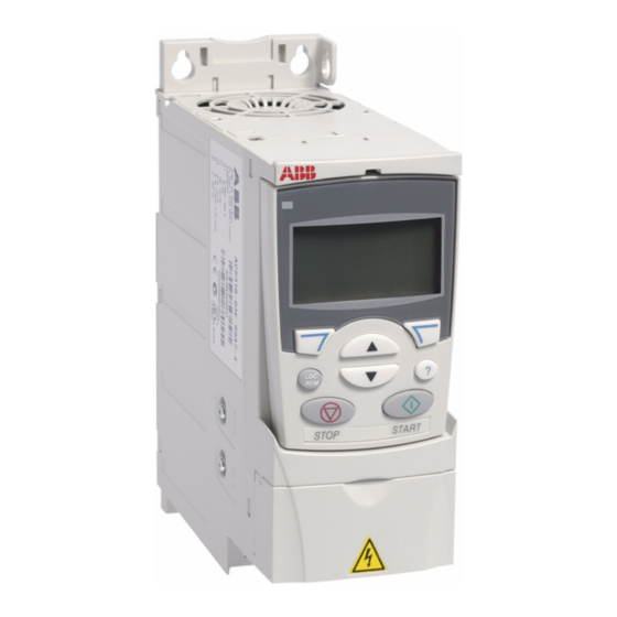
Aotewell Ltd www.aotewell.com Industry Automation 24 Operation principle and hardware description Product overview Layout The layout of the drive is presented below. The figure shows a frame size R2 drive. The construction of the different frame sizes R0…R4 varies to some extent. Covers on (R2) Covers off (R2) Cooling outlet through top cover... -
Page 25: Power Connections And Control Interfaces
Aotewell Ltd www.aotewell.com Industry Automation Operation principle and hardware description 25 Power connections and control interfaces The diagram gives an overview of connections. I/O connections are parameterable. See chapter Application macros on page for I/O connections for the different macros and chapter Electrical installation on page... -
Page 26: Type Designation Label
A, B, C, … for product revision number XXXX: Integer starting every week from 0001 5 ABB MRP code of the drive 6 CE marking and C-Tick, C-UL US and RoHS marks (the label of your drive shows the valid markings) HongKong|UK|China sales@aotewell.com... -
Page 27: Type Designation Key
R707 = ACS310 User’s Manual in French (3AUA0000048400 [FR]) R708 = ACS310 User’s Manual in Spanish (3AUA0000048401 [ES]) The ACS310 is compatible with panels that have the following panel revisions and panel firmware versions. To find out the revision and firmware version of your panel, see page 68. - Page 28 Aotewell Ltd www.aotewell.com Industry Automation 28 Operation principle and hardware description HongKong|UK|China sales@aotewell.com +86-755-8660-6182...
-
Page 29: Mechanical Installation
Aotewell Ltd www.aotewell.com Industry Automation Mechanical installation 29 Mechanical installation What this chapter contains The chapter tells how to check the installation site, unpack, check the delivery and install the drive mechanically. Checking the installation site The drive may be installed on the wall or in a cabinet. Check the enclosure requirements for the need to use the NEMA 1 option in wall installations (see chapter Technical data on page 335. -
Page 30: Required Tools
Aotewell Ltd www.aotewell.com Industry Automation 30 Mechanical installation Floor The floor/material below the installation should be non-flammable. Free space around the drive The required free space for cooling above and below the drive is 75 mm (3 in). No free space is required on the sides of the drive, so drives can be mounted immediately next to each other. -
Page 31: Unpacking
Aotewell Ltd www.aotewell.com Industry Automation Mechanical installation 31 Unpacking The drive (1) is delivered in a package that also contains the following items (frame size R2 shown in the figure): • plastic bag (2) including clamping plate (also used for I/O cables in frame sizes R3 and R4), I/O clamping plate (for frame sizes R0…R2), clamps and screws •... -
Page 32: Installing
Aotewell Ltd www.aotewell.com Industry Automation 32 Mechanical installation Installing The instructions in this manual cover drives with the IP20 degree of protection. To comply with NEMA 1, use the MUL1-R1, MUL1-R3 or MUL1-R4 option kit, which is delivered with multilingual installation instructions (3AFE68642868, 3AFE68643147 or 3AUA0000025916, respectively). - Page 33 Aotewell Ltd www.aotewell.com Industry Automation Mechanical installation 33 3. Position the drive onto the screws on the wall. 4. Tighten the screws in the wall securely. On DIN rail 1. Click the drive to the rail. To detach the drive, press the release lever on top of the drive (1b). sales@aotewell.com +86-755-8660-6182 HongKong|UK|China...
-
Page 34: Fasten Clamping Plates
Aotewell Ltd www.aotewell.com Industry Automation 34 Mechanical installation Fasten clamping plates 1. Fasten the clamping plate to the plate at the bottom of the drive with the provided screws. 2. For frame sizes R0…R2, fasten the I/O clamping plate to the clamping plate with the provided screws. -
Page 35: Planning The Electrical Installation
Note: The installation must always be designed and made according to applicable local laws and regulations. ABB does not assume any liability whatsoever for any installation which breaches the local laws and/or other regulations. Furthermore, if the recommendations given by ABB are not followed, the drive may experience problems that the warranty does not cover. -
Page 36: European Union
Aotewell Ltd www.aotewell.com Industry Automation 36 Planning the electrical installation European union To meet the European Union Directives, according to standard EN 60204-1, Safety of Machinery, the disconnecting device must be one of the following types: • a switch-disconnector of utilization category AC-23B (EN 60947-3) •... -
Page 37: Alternative Power Cable Types
Aotewell Ltd www.aotewell.com Industry Automation Planning the electrical installation 37 Alternative power cable types Power cable types that can be used with the drive are presented below. Motor cables Note: A separate PE conductor is required if the conductivity of the cable shield is not (recommended for input cables also) sufficient for the purpose. -
Page 38: Additional Us Requirements
Aotewell Ltd www.aotewell.com Industry Automation 38 Planning the electrical installation Additional US requirements Type MC continuous corrugated aluminium armor cable with symmetrical grounds or shielded power cable is recommended for the motor cables if metallic conduit is not used. The power cables must be rated for 75 °C (167 °F). -
Page 39: Relay Cable
Control panel cable In remote use, the cable connecting the control panel to the drive must not exceed 3 m (10 ft). The cable type tested and approved by ABB is used in control panel option kits. Routing the cables Route the motor cable away from other cable routes. -
Page 40: Control Cable Ducts
Aotewell Ltd www.aotewell.com Industry Automation 40 Planning the electrical installation A diagram of the cable routing is shown below. Motor cable min. 300 mm (12 in) Drive Power cable Motor cable Input power cable 90° min. 200 mm (8 in) min. -
Page 41: Protecting The Drive, Input Power Cable, Motor And Motor Cable In Short-Circuit Situations And Against Thermal Overload
Aotewell Ltd www.aotewell.com Industry Automation Planning the electrical installation 41 Protecting the drive, input power cable, motor and motor cable in short-circuit situations and against thermal overload Protecting the drive and input power cable in short-circuit situations Arrange the protection according to the following guidelines. Circuit diagram Short-circuit protection Protect the drive and input... -
Page 42: Using Residual Current Devices (Rcd) With The Drive
145. Using residual current devices (RCD) with the drive ACS310-03x drives are suitable to be used with residual current devices of Type B. Other measures for protection in case of direct or indirect contact, such as separation from the environment by double or reinforced insulation or isolation from the supply system by a transformer, can also be applied. - Page 43 Aotewell Ltd www.aotewell.com Industry Automation Planning the electrical installation 43 Install the protective component as close to the inductive load as possible. Do not install protective components at the I/O terminal block. Varistor Drive relay 230 V AC output RC filter Drive relay 230 V AC...
- Page 44 Aotewell Ltd www.aotewell.com Industry Automation 44 Planning the electrical installation HongKong|UK|China sales@aotewell.com +86-755-8660-6182...
-
Page 45: Electrical Installation
Aotewell Ltd www.aotewell.com Industry Automation Electrical installation 45 Electrical installation What this chapter contains The chapter tells how to check the insulation of the assembly and the compatibility with IT (ungrounded) and corner-grounded TN systems as well as connect power cables, control cables and embedded fieldbus. -
Page 46: Motor And Motor Cable
1. If you have an IT (ungrounded) or corner-grounded TN system, disconnect the internal EMC filter by removing the EMC screw. For 3-phase U-type drives (with type designation ACS310-03U-), the EMC screw is already removed at the factory and replaced by a plastic one. -
Page 47: Connecting The Power Cables
Aotewell Ltd www.aotewell.com Industry Automation Electrical installation 47 Connecting the power cables Connection diagram Drive INPUT OUTPUT U1 V1 W1 U2 V2 W2 For alternatives, see section Selecting the supply disconnecting device (disconnecting means) page 35. Motor L1 L2 (L) (N) Ground the other end of the PE conductor at the distribution board. -
Page 48: Connection Procedure
Aotewell Ltd www.aotewell.com Industry Automation 48 Electrical installation Connection procedure 1. Fasten the grounding conductor (PE) of the input power cable under the grounding clamp. Connect the phase conductors to the U1, V1 and W1 terminals. Use a tightening torque of 0.8 N·m (7 lbf·in) for frame sizes R0…R2, 1.7 N·m (15 lbf·in) for R3, and 2.5 N·m (22 lbf·in) for R4. -
Page 49: Connecting The Control Cables
Aotewell Ltd www.aotewell.com Industry Automation Electrical installation 49 Connecting the control cables I/O terminals The figure below shows the I/O terminals. Tightening torque is 0.4 N·m (3.5 lbf·in). X1A: X1B: J701 1: SCR 17: ROCOM 2: AI1 18: RONC 3: GND 19: RONO 4: +10 V... - Page 50 Aotewell Ltd www.aotewell.com Industry Automation 50 Electrical installation Voltage and current connection for analog inputs Bipolar voltage (-10…10 V) and current (-20…20 mA) are also possible. If a bipolar connection is used instead of a unipolar one, see section Programmable analog inputs on page for how to set parameters accordingly.
- Page 51 Aotewell Ltd www.aotewell.com Industry Automation Electrical installation 51 Connection examples of two-wire and three-wire sensors Hand/Auto, PID control, PFC control and SPFC control macros (see section Application macros on page 101) use analog input 2 (AI2). The macro wiring diagrams on these pages use an externally powered sensor (connections not shown). The figures below gives example of a connections using a two-wire or three-wire sensor/transmitter supplied by the drive auxiliary voltage output.
-
Page 52: Default I/O Connection Diagram
165. For information on other macros, see chapter Application macros on page 101. The default I/O connections for the ABB standard macro are given in the figure below. Signal cable shield (screen) Output frequency reference: 0…10 V 1…10 kohm... -
Page 53: Connection Procedure
Aotewell Ltd www.aotewell.com Industry Automation Electrical installation 53 Connection procedure 1. Remove the terminal cover by simultaneously pushing the recess and sliding the cover off the frame. 2. Digital signals: Strip the outer insulation of the digital signal cable 360 degrees and ground the bare shield under the clamp. -
Page 54: Connecting The Embedded Fieldbus
Aotewell Ltd www.aotewell.com Industry Automation 54 Electrical installation Connecting the embedded fieldbus Embedded fieldbus is connected to the drive with EIA-485 or RS-232. Connection diagram EIA-485 The figure below shows the fieldbus connection. J701 GND_A 23 SCR Fieldbus cable shield (screen) 24 B Positive 25 A... -
Page 55: Installation Checklist
Aotewell Ltd www.aotewell.com Industry Automation Installation checklist 55 Installation checklist Checking the installation Check the mechanical and electrical installation of the drive before start-up. Go through the checklist below together with another person. Read chapter Safety page of this manual before you work on the drive. Check MECHANICAL INSTALLATION The ambient operating conditions are within allowed limits. - Page 56 Aotewell Ltd www.aotewell.com Industry Automation 56 Installation checklist Check The motor cable, input power cable and control cables are routed separately. The external control (I/O) connections are OK. The input power voltage cannot be applied to the output of the drive (with a bypass connection).
-
Page 57: Start-Up And Control With I/O
Aotewell Ltd www.aotewell.com Industry Automation Start-up and control with I/O 57 Start-up and control with I/O What this chapter contains The chapter tells how to: • perform the start-up • start, stop, change the direction of the motor rotation and adjust the speed of the motor through the I/O interface Using the control panel to do these tasks is explained briefly in this chapter. -
Page 58: How To Start Up The Drive Without A Control Panel
Aotewell Ltd www.aotewell.com Industry Automation 58 Start-up and control with I/O • Check the installation. See the checklist in chapter Installation checklist on page How you start up the drive depends on the control panel you have, if any. • If you have no control panel, follow the instructions given in section How to start up the drive without a control panel on page 58. -
Page 59: How To Perform A Manual Start-Up
Enter the motor data from the motor nameplate: Note: Set the motor data to exactly the same value as on the motor nameplate. For ABB Motors example, if the nominal motor speed is 1470 rpm on the motor M2AA 200 MLA 4... - Page 60 • nominal motor speed (parameter 9908) 9908 • nominal motor power (parameter 9909) 9909 Select the application macro (parameter 9902) 9902 according to how the control cables are connected. The default value 1 (ABB STANDARD) is suitable in most cases. sales@aotewell.com +86-755-8660-6182 HongKong|UK|China...
- Page 61 Aotewell Ltd www.aotewell.com Industry Automation Start-up and control with I/O 61 DIRECTION OF THE MOTOR ROTATION Check the direction of the motor rotation. • If the drive is in remote control (REM shown on the left), switch to local control by pressing •...
-
Page 62: How To Perform A Guided Start-Up
Aotewell Ltd www.aotewell.com Industry Automation 62 Start-up and control with I/O How to perform a guided start-up To be able to perform the guided start-up, you need the Assistant control panel. Before you start, ensure that you have the motor nameplate data on hand. POWER-UP Apply input power. - Page 63 Industry Automation Start-up and control with I/O 63 Select the application macro according to which the PAR EDIT control cables are connected. 9902 APPLIC MACRO ABB STANDARD EXIT 00:00 SAVE Continue with the application set-up. After CHOICE Do you want to...
- Page 64 Aotewell Ltd www.aotewell.com Industry Automation 64 Start-up and control with I/O FINAL CHECK After the whole set-up is completed, check that there are no faults or alarms shown on the display and the panel LED is green and does not blink. The drive is now ready for use.
-
Page 65: How To Control The Drive Through The I/O Interface
Default I/O connection diagram on page according to the connection diagram given for the ABB standard macro. Ensure that the drive is in remote control. Press key In remote control, the panel display shows text REM. to switch between remote and local control. - Page 66 Aotewell Ltd www.aotewell.com Industry Automation 66 Start-up and control with I/O sales@aotewell.com +86-755-8660-6182 HongKong|UK|China...
-
Page 67: Control Panels
About control panels Use a control panel to control the ACS310, read status data, and adjust parameters. The drive works with either of two different control panel types: •... - Page 68 68 Control panels To find out the panel revision, see the label on the back of the panel. An example label and explanation of the label contents are shown below. ABB Oy, ACS-CP-A S/N M0935E0001 RoHS 1 Panel type code...
-
Page 69: Basic Control Panel
Aotewell Ltd www.aotewell.com Industry Automation Control panels 69 Basic control panel Features The Basic control panel features: • numeric control panel with an LCD display • copy function – parameters can be copied to the control panel memory for later transfer to other drives or for backup of a particular system. -
Page 70: Overview
Aotewell Ltd www.aotewell.com Industry Automation 70 Control panels Overview The following table summarizes the key functions and displays on the Basic control panel. No. Use LCD display – Divided into five areas: a. Upper left – Control location: LOC: drive control is local, that is, from the control panel REM: drive control is remote, such as the drive OUTPUT... -
Page 71: Operation
Aotewell Ltd www.aotewell.com Industry Automation Control panels 71 Operation You can operate the control panel with the help of menus and keys. You can select an option, for example, an operation mode or parameter, by scrolling the arrow keys until the option is visible on the display and then pressing the key. - Page 72 Aotewell Ltd www.aotewell.com Industry Automation 72 Control panels How to find out the panel firmware version Step Action Display If the power is switched on, switch it off. Keep key pressed down while you switch on the X X X power and read the panel firmware version shown on the display.
- Page 73 Aotewell Ltd www.aotewell.com Industry Automation Control panels 73 How to change the direction of the motor rotation You can change the direction of the motor rotation in any mode. Step Action Display If the drive is in remote control (REM shown on the left), switch to local control by pressing .
-
Page 74: Output Mode
Aotewell Ltd www.aotewell.com Industry Automation 74 Control panels Output mode In the Output mode, you can: • monitor actual values of up to three group 01 OPERATING DATA signals, one signal at a time • start, stop, change the direction and switch between local and remote control. You can enter the Output mode by pressing until the display shows text OUTPUT at the bottom. -
Page 75: Reference Mode
Aotewell Ltd www.aotewell.com Industry Automation Control panels 75 Reference mode In the Reference mode, you can: • set the frequency reference • start, stop, change the direction and switch between local and remote control. How to set the frequency reference Step Action Display Go to the Main menu by pressing... -
Page 76: Parameter Mode
Aotewell Ltd www.aotewell.com Industry Automation 76 Control panels Parameter mode In the Parameter mode, you can: • view and change parameter values • select and modify the signals shown in the Output mode • start, stop, change the direction and switch between local and remote control. How to select a parameter and change its value Step Action Display... - Page 77 Aotewell Ltd www.aotewell.com Industry Automation Control panels 77 How to select the monitored signals Step Action Display You can select which signals are monitored in the Output mode and how they are displayed with group 34 PANEL DISPLAY parameters. See page detailed instructions on changing parameter values.
-
Page 78: Copy Mode
Aotewell Ltd www.aotewell.com Industry Automation 78 Control panels Copy mode The Basic control panel can store a full set of drive parameters and up to two user sets of drive parameters to the control panel. Uploading and downloading can be performed in local control. -
Page 79: Basic Control Panel Alarm Codes
Aotewell Ltd www.aotewell.com Industry Automation Control panels 79 How to upload and download parameters For the upload and download functions available, see above. Note that the drive has to be in local control for uploading and downloading. Step Action Display Go to the Main menu by pressing if you are in the Output mode, otherwise by pressing... -
Page 80: Assistant Control Panel
Aotewell Ltd www.aotewell.com Industry Automation 80 Control panels Assistant control panel Features The Assistant control panel features: • alphanumeric control panel with an LCD display • language selection for the display • Start-up assistant to ease drive commissioning • copy function – parameters can be copied to the control panel memory for later transfer to other drives or for backup of a particular system. -
Page 81: Overview
Aotewell Ltd www.aotewell.com Industry Automation Control panels 81 Overview The following table summarizes the key functions and displays on the Assistant control panel No. Use Status LED – Green for normal operation. If LED is flashing, or red, see section LEDs on page 333. -
Page 82: Operation
Aotewell Ltd www.aotewell.com Industry Automation 82 Control panels Status line The top line of the LCD display shows the basic status information of the drive. MAIN MENU 49.1Hz No. Field Alternatives Significance Control location Drive control is local, that is, from the control panel. - Page 83 Aotewell Ltd www.aotewell.com Industry Automation Control panels 83 Initially, the panel is in the Output mode, where you can 49.1Hz 49 1 Hz start, stop, change the direction, switch between local and 0 5 A remote control, modify the reference value and monitor up 10 7 % to three actual values.
- Page 84 Aotewell Ltd www.aotewell.com Industry Automation 84 Control panels How to get help Step Action Display Press to read the context-sensitive help text for the PAR GROUPS item that is highlighted. 01 OPERATING DATA 03 FB ACTUAL SIGNALS 04 FAULT HISTORY 10 START/STOP/DIR 11 REFERENCE SELECT 00:00...
- Page 85 Aotewell Ltd www.aotewell.com Industry Automation Control panels 85 How to start, stop and switch between local and remote control You can start, stop and switch between local and remote control in any mode. To be able to start or stop the drive, the drive must be in local control. Step Action Display •...
-
Page 86: Output Mode
Aotewell Ltd www.aotewell.com Industry Automation 86 Control panels Output mode In the Output mode, you can: • monitor actual values of up to three signals in group 01 OPERATING DATA • change the direction of the motor rotation • set the frequency reference •... - Page 87 Aotewell Ltd www.aotewell.com Industry Automation Control panels 87 How to set the frequency reference Step Action Display EXIT If you are not in the Output mode, press repeatedly 49.1Hz until you get there. 49 1 Hz 0 5 A 10 7 % 00:00 MENU If the drive is in remote control (REM shown on the status...
-
Page 88: Parameters Mode
EDIT Select the appropriate parameter with keys PARAMETERS . The current value of the parameter is shown 9901 LANGUAGE 9902 APPLIC MACRO below the selected parameter. ABB STANDARD 9905 MOTOR NOM VOLT 9906 MOTOR NOM CURR 00:00 EXIT EDIT EDIT... - Page 89 Aotewell Ltd www.aotewell.com Industry Automation Control panels 89 Step Action Display SAVE • To save the new value, press PARAMETERS 9901 LANGUAGE • To cancel the new value and keep the original, press 9902 APPLIC MACRO CANCEL 3-WIRE 9905 MOTOR NOM VOLT 9906 MOTOR NOM CURR 00:00 EDIT...
- Page 90 Aotewell Ltd www.aotewell.com Industry Automation 90 Control panels Step Action Display Select the scalings for the signals by specifying the PAR EDIT minimum and maximum display values. This has no 3406 OUTPUT1 MIN effect if parameter 3404/3411/3418 is set to 9 (DIRECT). 0.0 Hz For details, see parameters 3406...
-
Page 91: Assistants Mode
Aotewell Ltd www.aotewell.com Industry Automation Control panels 91 Assistants mode When the drive is first powered up, the Start-up assistant guides you through the setup of the basic parameters. The Start-up assistant is divided into assistants, each of which is responsible for the specification of a related parameter set, for example Motor set-up or PID control. - Page 92 Aotewell Ltd www.aotewell.com Industry Automation 92 Control panels Step Action Display • To specify a new value, press keys PAR EDIT 9905 MOTOR NOM VOLT 240 V 00:00 SAVE EXIT • To ask for information on the requested parameter, HELP press key .
-
Page 93: Changed Parameters Mode
Aotewell Ltd www.aotewell.com Industry Automation Control panels 93 Changed parameters mode In the Changed parameters mode, you can: • view a list of all parameters that have been changed from the macro default values • change these parameters • start, stop, change the direction and switch between local and remote control. How to view and edit changed parameters Step Action Display... -
Page 94: Fault Logger Mode
Aotewell Ltd www.aotewell.com Industry Automation 94 Control panels Fault logger mode In the Fault logger mode, you can: • view the drive fault history of maximum ten faults (after a power off, only the three latest faults are kept in the memory) •... -
Page 95: Time And Date Mode
Aotewell Ltd www.aotewell.com Industry Automation Control panels 95 Time and date mode In the Time and date mode, you can: • show or hide the clock • change date and time display formats • set the date and time •... - Page 96 Aotewell Ltd www.aotewell.com Industry Automation 96 Control panels Step Action Display • To set the time, select SET TIME on the menu and SET TIME press . Specify the hours with keys , and press .Then specify the minutes. Press 15:41 CANCEL to save or...
-
Page 97: Parameter Backup Mode
Aotewell Ltd www.aotewell.com Industry Automation Control panels 97 Parameter backup mode The Parameter backup mode is used to export parameters from one drive to another or to make a backup of the drive parameters. Uploading to the panel stores all drive parameters, including up to two user sets, to the Assistant control panel. - Page 98 Aotewell Ltd www.aotewell.com Industry Automation 98 Control panels How to upload and download parameters For the upload and download functions available, see above. Note that the drive has to be in local control for uploading and downloading. Step Action Display MENU Go to the Main menu by pressing if you are in the...
- Page 99 00:00 Select BACKUP INFO on the Par backup menu with keys BACKUP INFO , and press . The display shows the DRIVE TYPE ACS310 following information about the drive where the backup 3304 DRIVE RATING was made: 9A74i 3301 FIRMWARE...
-
Page 100: Io Settings Mode
Aotewell Ltd www.aotewell.com Industry Automation 100 Control panels IO settings mode In the IO settings mode, you can: • check the parameter settings related to any I/O terminal • edit the parameter setting. For example, if “1103: REF1” is listed under Ain1 (Analog input 1), that is, parameter 1103 REF1 SELECT has value AI1, you can... -
Page 101: Application Macros
9902 APPLIC MACRO, makes the essential changes and saves the result as a user macro. The ACS310 has eight standard macros and two user macros. The table below contains a summary of the macros and describes suitable applications. Macro Suitable applications... - Page 102 Aotewell Ltd www.aotewell.com Industry Automation 102 Application macros Macro Suitable applications PID control Process control applications, for example different closed loop control systems such as pressure control, level control and flow control. It is possible to switch between process and speed control: Some control signal terminals are reserved for process control, others for speed control.
-
Page 103: Summary Of The I/O Connections Of The Application Macros
Aotewell Ltd www.aotewell.com Industry Automation Application macros 103 Summary of the I/O connections of the application macros The following table gives the summary of the default I/O connections of all application macros. Input/ Macro output 3-wire Alternate Motor Hand/ AC500 standard potentiom. -
Page 104: Abb Standard Macro
Aotewell Ltd www.aotewell.com Industry Automation 104 Application macros ABB standard macro This is the default macro. It provides a general purpose I/O configuration with three constant speeds. Parameter values are the default values given in section parameters on page 177. -
Page 105: 3-Wire Macro
Aotewell Ltd www.aotewell.com Industry Automation Application macros 105 3-wire macro This macro is used when the drive is controlled using momentary push-buttons. It provides three constant speeds. To enable the macro, set the value of parameter 9902 APPLIC MACRO to 2 (3-WIRE). For the parameter default values, see section Default values with different macros page 165. -
Page 106: Alternate Macro
Aotewell Ltd www.aotewell.com Industry Automation 106 Application macros Alternate macro This macro provides an I/O configuration adapted to a sequence of DI control signals used when alternating the rotation direction of the motor. To enable the macro, set the value of parameter 9902 APPLIC MACRO to 3 (ALTERNATE). -
Page 107: Motor Potentiometer Macro
Aotewell Ltd www.aotewell.com Industry Automation Application macros 107 Motor potentiometer macro This macro provides a cost-effective interface for PLCs that vary the speed (output frequency) of the motor using only digital signals. To enable the macro, set the value of parameter 9902 APPLIC MACRO to 4 (MOTOR... -
Page 108: Hand/Auto Macro
Aotewell Ltd www.aotewell.com Industry Automation 108 Application macros Hand/Auto macro This macro can be used when switching between two external control devices is needed. To enable the macro, set the value of parameter 9902 APPLIC MACRO 5 (HAND/AUTO). For the parameter default values, see section Default values with different macros page 165. -
Page 109: Pid Control Macro
Aotewell Ltd www.aotewell.com Industry Automation Application macros 109 PID control macro This macro provides parameter settings for closed-loop control systems such as pressure control, flow control, etc. Control can also be switched to speed control using a digital input. To enable the macro, set the value of parameter 9902 APPLIC MACRO to 6... -
Page 110: Pfc Control Macro
Aotewell Ltd www.aotewell.com Industry Automation 110 Application macros PFC control macro This macro provides parameter settings for pump and fan control (PFC) applications. To enable the macro, set the value of parameter 9902 APPLIC MACRO to 7 (PFC CONTROL). For the parameter default values, see section Default values with different macros page 165. -
Page 111: Spfc Control Macro
Aotewell Ltd www.aotewell.com Industry Automation Application macros 111 SPFC control macro This macro provides parameter settings for pump and fan control (SPFC) applications with a soft start function. To enable the macro, set the value of parameter 9902 APPLIC MACRO to 15 (SPFC CONTROL). -
Page 112: User Macros
Aotewell Ltd www.aotewell.com Industry Automation 112 Application macros User macros In addition to the standard application macros, it is possible to create two user macros. The user macro allows the user to save the parameter settings, including group 99 START-UP DATA, into the permanent memory and recall the data at a later time. -
Page 113: Ac500 Modbus Macro
Application macros 113 AC500 Modbus macro The AC500 Modbus application macro configures the ACS310 drive communication and control parameters. The macro is available in ACS310 drives with firmware manual version 4.050 or later. To activate the macro, set parameter 9902 APPLIC... - Page 114 114 Application macros Parameter Default value 5304 EFB PARITY (8 NONE 5305 EFB CTRL PROFILE (ABB DRV FULL) 5310 EFB PAR 10 5311 EFB PAR 11 5312 EFB PAR 12 Note: The default slave address of the drive is 2 (parameter...
-
Page 115: Program Features
Aotewell Ltd www.aotewell.com Industry Automation Program features 115 Program features What this chapter contains The chapter describes program features. For each feature, there is a list of related user settings, actual signals, and fault and alarm messages. Start-up assistant Introduction The Start-up assistant (requires the Assistant control panel) guides the user through the start-up procedure, helping to enter the requested data (parameter values) to the... -
Page 116: Default Order Of The Tasks
MACRO), the Start-up assistant decides which consequent tasks it suggests. The default tasks are shown in the table below. Application selection Default tasks ABB STANDARD Language select, Motor set-up, Application, Option modules, Speed control EXT1, Speed control EXT2, Start/Stop control, Timed functions, Protections, Output signals... -
Page 117: List Of The Tasks And The Relevant Drive Parameters
Aotewell Ltd www.aotewell.com Industry Automation Program features 117 List of the tasks and the relevant drive parameters Depending on the selection made in the Application task (parameter 9902 APPLIC MACRO), the Start-up assistant decides which consequent tasks it suggests. Name Description Set parameters... - Page 118 Aotewell Ltd www.aotewell.com Industry Automation 118 Program features Name Description Set parameters Output signals Output signals Selecting the signals Group 14 RELAY indicated through relay output RO1 and, if OUTPUTS the MREL relay output extension module is in use, RO2…RO4. Selecting the signals indicated through Group 15 ANALOG...
-
Page 119: Contents Of The Assistant Displays
Aotewell Ltd www.aotewell.com Industry Automation Program features 119 Contents of the assistant displays There are two types of displays in the Start-up assistant: Main displays and information displays. The main displays prompt the user to feed in information. The assistant steps through the main displays. -
Page 120: Local Control
Aotewell Ltd www.aotewell.com Industry Automation 120 Program features Local control The control commands are given from the control panel keypad when the drive is in local control. LOC indicates local control on the panel display. Assistant control panel Basic control panel 49.1Hz 49 1 Hz 0 5 A... -
Page 121: Diagnostics
Aotewell Ltd www.aotewell.com Industry Automation Program features 121 Diagnostics Actual signals Additional information 0111/0112 EXT1/EXT2 reference Block diagram: Start, stop, direction source for EXT1 The figure below shows the parameters that select the interface for start, stop, and direction for external control location EXT1. -
Page 122: Reference Types And Processing
Aotewell Ltd www.aotewell.com Industry Automation 122 Program features Reference types and processing The drive can accept a variety of references in addition to the conventional analog input and control panel signals. • The drive reference can be given with two digital inputs: One digital input increases the speed, the other decreases it. -
Page 123: Reference Trimming
Aotewell Ltd www.aotewell.com Industry Automation Program features 123 Reference trimming In reference trimming, the external reference is corrected depending on the measured value of a secondary application variable. The block diagram below illustrates the function. Switch Select 1105 REF1 MAX 2 (DIRECT) 1108 REF2 MAX REF1... -
Page 124: Example
Aotewell Ltd www.aotewell.com Industry Automation 124 Program features Example The drive runs a conveyor line. It is speed controlled but the line tension also needs to be taken into account: If the measured tension exceeds the tension setpoint, the speed is slightly decreased, and vice versa. -
Page 125: Diagnostics
Aotewell Ltd www.aotewell.com Industry Automation Program features 125 Diagnostics Actual signal Additional information 0120, 0121 Analog input values 1401 AI1/A2 signal loss Alarm AI1 LOSS AI2 LOSS AI1/AI2 signal below limit 3021 AI1 FAULT LIMIT 3022 AI2 FAULT LIMIT Fault AI1 LOSS AI2 LOSS... -
Page 126: Programmable Digital Inputs
Aotewell Ltd www.aotewell.com Industry Automation 126 Program features Programmable digital inputs The drive has five programmable digital inputs. The update time for the digital inputs is 2 ms. It is possible to delay the state change of digital inputs with delays defined in group 18 FREQ IN &... -
Page 127: Diagnostics
Aotewell Ltd www.aotewell.com Industry Automation Program features 127 Diagnostics Actual signal Additional information 0160 DI status 0414 DI status at the time the latest fault occurred Programmable relay output The drive has one programmable relay output. It is possible to add three additional relay outputs with the optional MREL relay output extension module. -
Page 128: Diagnostics
Aotewell Ltd www.aotewell.com Industry Automation 128 Program features Diagnostics Actual signal Additional information 0161 Frequency input value Transistor output The drive has one programmable transistor output. The output can be used either as a digital output or frequency output (0…16000 Hz). The update time for the transistor/frequency output is 2 ms. -
Page 129: Diagnostics
Aotewell Ltd www.aotewell.com Industry Automation Program features 129 Parameter Additional information Group 34 PANEL DISPLAY Selection of an actual signals to be displayed on the control panel Diagnostics Actual signal Additional information Groups 01 OPERATING DATA … Lists of actual signals 04 FAULT HISTORY Power loss ride-through If the incoming supply voltage is cut off, the drive continues to operate by utilizing the... -
Page 130: Dc Magnetizing
Aotewell Ltd www.aotewell.com Industry Automation 130 Program features DC magnetizing When DC magnetizing is activated, the drive automatically magnetizes the motor before starting. This feature guarantees the highest possible break-away torque, up to 180% of the nominal motor torque. The Automatic start feature and DC magnetizing cannot be activated at the same time. -
Page 131: Motor Heating Function
Aotewell Ltd www.aotewell.com Industry Automation Program features 131 Motor heating function With the motor heating function, DC current can be injected into the motor to keep it warm in low temperatures. The function can be enabled with parameter 2104 DC HOLD CTL. - Page 132 Aotewell Ltd www.aotewell.com Industry Automation 132 Program features Constant speed 7 (1208 CONST SPEED 7) is also used for fault functions. See parameter group 30 FAULT FUNCTIONS. HongKong|UK|China sales@aotewell.com +86-755-8660-6182...
-
Page 133: Custom U/F Ratio
Aotewell Ltd www.aotewell.com Industry Automation Program features 133 Custom U/f ratio The user can define a U/f curve (output voltage as a function of frequency). This custom ratio is used only in special applications where linear and squared U/f ratio are not sufficient (eg when motor break-away torque needs to be boosted). -
Page 134: Ir Compensation
Aotewell Ltd www.aotewell.com Industry Automation 134 Program features IR compensation When IR compensation is activated, the drive Motor voltage gives an extra voltage boost to the motor at low speeds. IR compensation is useful in IR compensation applications that require high break-away torque. ... -
Page 135: Motor Thermal Protection
Aotewell Ltd www.aotewell.com Industry Automation Program features 135 Motor thermal protection The motor can be protected against overheating by activating the Motor thermal protection function. The drive calculates the temperature of the motor on the basis of the following assumptions: 1. -
Page 136: Input Phase Loss
Aotewell Ltd www.aotewell.com Industry Automation 136 Program features Settings Parameter 3023 WIRING FAULT Input phase loss Input phase loss protection circuits supervise the input power cable connection status by detecting intermediate circuit ripple. If a phase is lost, the ripple increases. Settings Parameter 3016 SUPPLY PHASE... -
Page 137: Power Limit
Aotewell Ltd www.aotewell.com Industry Automation Program features 137 Power limit Power limitation is used to protect the input bridge and the DC intermediate circuit. If the maximum allowed power is exceeded, the drive torque is automatically limited. Maximum overload and continuous power limits depend on the drive hardware. For specific values, see chapter Technical data on page 335. -
Page 138: Parameter Lock
Aotewell Ltd www.aotewell.com Industry Automation 138 Program features Parameter lock The user can prevent parameter adjustment by activating the parameter lock. Settings Parameters 1602 PARAMETER LOCK 1603 PASS CODE PID control There are two built-in PID controllers in the drive: •... -
Page 139: Block Diagrams
Aotewell Ltd www.aotewell.com Industry Automation Program features 139 Block diagrams The figure below shows an application example: The controller adjusts the speed of a pressure boost pump according to the measured pressure and the set pressure reference. Example: PID control block diagram Pressure boost pump %ref A C S 6 0 0... - Page 140 Aotewell Ltd www.aotewell.com Industry Automation 140 Program features The following figure presents the speed/scalar control block diagram for process controller PID1. HongKong|UK|China sales@aotewell.com +86-755-8660-6182...
-
Page 141: Settings
Aotewell Ltd www.aotewell.com Industry Automation Program features 141 Settings Parameter Additional information 1101 Local control mode reference type selection 1102 EXT1/EXT2 selection 1106 PID1 activation 1107 REF2 minimum limit 1501 PID2 output (external controller) connection to AO 9902 PID control macro selection Groups 40 PROCESS PID SET PID1 settings... - Page 142 Aotewell Ltd www.aotewell.com Industry Automation 142 Program features Use timers to control the bits sent to the digital inputs as shown in the table below. Enable setpoint selection through the digital inputs, set 4039 INT SETPNT SEL to, for example, DI1,2 (7). Day 1 Day 2 Day 3...
-
Page 143: Sleep Function For The Process Pid (Pid1) Control
Aotewell Ltd www.aotewell.com Industry Automation Program features 143 Sleep function for the process PID (PID1) control The sleep function operates on a 2 ms time level. The block diagram below illustrates the sleep function enable/disable logic. The sleep function can be put into use only when the PID control is active. Compare Select NOT SEL... -
Page 144: Example
Aotewell Ltd www.aotewell.com Industry Automation 144 Program features Example The time scheme below visualizes the operation of the sleep function. Reference Sleep boost time (4030) Sleep boost step (4031) Time Wake-up delay Selected process (4026) actual value Wake-up level deviation (4025) Time Output frequency... -
Page 145: Settings
Aotewell Ltd www.aotewell.com Industry Automation Program features 145 Settings Parameter Additional information 9902 PID control activation 4022…4026, 4030, 4031, Sleep function settings 4122…4126, 4130, 4131 Diagnostics Parameter Additional information 1401 PID sleep function status through RO 1 1402/1403/1410 PID sleep function status through RO 2…4. -
Page 146: Settings
Aotewell Ltd www.aotewell.com Industry Automation 146 Program features It is also possible to monitor motor temperature by connecting a PTC sensor and a thermistor relay between the +24 V DC voltage supply offered by the drive and a digital input. The figure below displays the connection. Par. -
Page 147: Timed Functions
Aotewell Ltd www.aotewell.com Industry Automation Program features 147 Timed functions A variety of drive functions can be time controlled, eg start/stop and EXT1/EXT2 control. The drive offers • four start and stop times (START TIME 1…START TIME STOP TIME 1…STOP TIME •... -
Page 148: Examples
Aotewell Ltd www.aotewell.com Industry Automation 148 Program features A parameter which is triggered by a timed function can be connected to only one timed function at a time. 1001 EXT1 COMMANDS Timed function 1 1002 EXT2 COMMANDS 3626 TIMED FUNC 1 SRC 1102 EXT1/EXT2 SEL 1201 CONST SPEED SEL Timed function 2... -
Page 149: Settings
Aotewell Ltd www.aotewell.com Industry Automation Program features 149 drive runs continuously from 18:00 (6 p.m.) on Friday evening to 06:30 (6:30 a.m.) on Monday morning. Timed function is enabled on the rising edge of digital input DI1. Parameter Setting 3601 TIMERS ENABLE DI1 CMODE 3602 START TIME 1 18:00:00... -
Page 150: User Load Curve
Aotewell Ltd www.aotewell.com Industry Automation 150 Program features User load curve The user can specify a load curve (motor torque as a function of frequency) for supervision. The curve is defined by five points. Supervision can be set for the torque dropping below the underload curve, exceeding the overload curve, or both. -
Page 151: Energy Optimizer
Aotewell Ltd www.aotewell.com Industry Automation Program features 151 Energy optimizer Energy optimizer optimizes the flux so that the total energy consumption and motor noise level are reduced when the drive operates below the nominal load. The total efficiency (motor and drive) can be improved by 1…10% depending on the load torque and speed. -
Page 152: Pump Cleaning
Aotewell Ltd www.aotewell.com Industry Automation 152 Program features Pump cleaning The Pump cleaning function can be used for preventing solids from building up on pump impellers. The function consists of a programmable sequence of forward and reverse runs of the pump (see the figure below), effectively shaking off any residue on the impeller. -
Page 153: Load Analyzer
Aotewell Ltd www.aotewell.com Industry Automation Program features 153 Load analyzer The load analyzer can be used for analyzing the customer’s process and sizing the drive and the motor. Peak value logger The user can select a signal (group 01 OPERATING DATA) to be monitored by the peak value logger (PVL). -
Page 154: Settings
Aotewell Ltd www.aotewell.com Industry Automation 154 Program features Settings Parameter Additional information Group 64 LOAD ANALYZER, Load analyzer settings parameters 6401…6405 Diagnostics Actual signal Additional information Group 64 LOAD ANALYZER, Load analyzer results parameters 6406…6433 HongKong|UK|China sales@aotewell.com +86-755-8660-6182... -
Page 155: Pfc And Spfc Control
Aotewell Ltd www.aotewell.com Industry Automation Program features 155 PFC and SPFC control PFC control Pump and fan control (PFC) switches auxiliary pumps on and off as required by capacity changes. Autochange function alternates between pumps to keep the duty times of the pumps equal. - Page 156 Aotewell Ltd www.aotewell.com Industry Automation 156 Program features motors. The main difference between traditional PFC and SPFC is the way SPFC connects auxiliary motors on-line. SPFC connects auxiliary motors online with a flying start, while the motor is still coasting. Thus, in some cases SPFC makes it possible to soften the start-up current while connecting auxiliary motors on-line.
- Page 157 Aotewell Ltd www.aotewell.com Industry Automation Program features 157 7. The drive waits for 8122 PFC START DELAY to ensure that the contactor (RO 2) has stabilized. 8. After delay 8122, the drive starts modulating from zero speed regulating the speed of motor 2. RO 1 is closed and motor 1 is connected directly on-line as an auxiliary motor.
-
Page 158: Settings
Aotewell Ltd www.aotewell.com Industry Automation 158 Program features Settings Parameter Additional information Group 14 RELAY OUTPUTS Selections of relay outputs for starting and stopping of motors Group 18 FREQ IN & TRAN OUT Selections of relay outputs for starting and stopping of motors (transistor output can be used as an additional relay) Group... -
Page 159: Connection Diagram Example
Aotewell Ltd www.aotewell.com Industry Automation Program features 159 Connection diagram example HongKong|UK|China sales@aotewell.com +86-755-8660-6182... -
Page 160: Pipe Fill
Aotewell Ltd www.aotewell.com Industry Automation 160 Program features Pipe fill The Pipe fill function is used for soft-starting a pump system. The pipe system is filled smoothly with water, and when the pressure in the pipe system is near the final set point, the drive changes to closed loop control. -
Page 161: Pid Reference Ramping
Aotewell Ltd www.aotewell.com Industry Automation Program features 161 PID reference ramping After PID deviation is below PID ENABLE DEV, PID reference ramping is enabled. The PID reference ramping parameters are in group 40. Final setpoint Change over Actual pressure Time Pump motor speed Time... - Page 162 Aotewell Ltd www.aotewell.com Industry Automation 162 Program features HongKong|UK|China sales@aotewell.com +86-755-8660-6182...
-
Page 163: Actual Signals And Parameters
Aotewell Ltd www.aotewell.com Industry Automation Actual signals and parameters 163 Actual signals and parameters What this chapter contains The chapter describes the actual signals and parameters and gives the fieldbus equivalent values for each signal/parameter. It also contains a table of the default values for the different macros. -
Page 164: Fieldbus Equivalent
Aotewell Ltd www.aotewell.com Industry Automation 164 Actual signals and parameters Fieldbus equivalent Example: If 2008 MAXIMUM FREQ (see page 200) is set from an external control system, an integer value of 1 corresponds to 0.1 Hz. All the read and sent values are limited to 16 bits (-32768…32767). -
Page 165: Default Values With Different Macros
Aotewell Ltd www.aotewell.com Industry Automation Actual signals and parameters 165 Default values with different macros When application macro is changed (9902 APPLIC MACRO), the software updates the parameter values to their default values. The table below shows the parameter default values for different macros. For other parameters, the default values are the same for all macros. - Page 166 Aotewell Ltd www.aotewell.com Industry Automation 166 Actual signals and parameters Index Name/ 3-WIRE ALTERNA MOTOR HAND/ SPFC AC500 Selection STAND AUTO CONTROL CONTROL CONTROL MODBUS 4001 GAIN 4002 INTEGRATIO 60.0 s 60.0 s 60.0 s 60.0 s 60.0 s 60.0 s 3.0 s 3.0 s 60.0 s...
-
Page 167: Actual Signals In The Short Parameter View
Aotewell Ltd www.aotewell.com Industry Automation Actual signals and parameters 167 Actual signals in the short parameter view Actual signals in the short parameter view Name/Value Description FbEq 04 FAULT HISTORY Fault history (read-only). See group 04 FAULT HISTORY the list of all parameters. 0401 LAST FAULT Code of the latest fault. -
Page 168: Accel/Decel
Defines the use of parity and stop bit(s) and the data length. 8 NONE 1 The same setting must be used in all on-line stations. 5305 EFB CTRL Selects the communication profile. See section ABB DRV PROFILE Communication profiles on page 302. 5306 EFB OK Number of valid messages received by the drive. -
Page 169: 98 Options
Actual signals and parameters 169 Parameters in the short parameter view Name/Value Description Def/FbEq 5319 EFB PAR 19 ABB drives profile (ABB DRV LIM ABB DRV FULL) 0000 hex Control word. Read only copy of the Fieldbus Control word. 5320 EFB PAR 20... -
Page 170: All Actual Signals
Aotewell Ltd www.aotewell.com Industry Automation 170 Actual signals and parameters All actual signals All actual signals Name/Value Description FbEq 01 OPERATING Basic signals for monitoring the drive (read-only) DATA 0101 SPEED & DIR Calculated motor speed in rpm. A negative value indicates 1 = 1 rpm reverse direction. - Page 171 Aotewell Ltd www.aotewell.com Industry Automation Actual signals and parameters 171 All actual signals Name/Value Description FbEq 0129 PID 2 SETPNT Setpoint signal (reference) for the PID2 controller. Unit depends on parameter 4106 UNITS 4107 UNIT SCALE settings. 0130 PID 1 FBK Feedback signal for the process PID1 controller.
- Page 172 Aotewell Ltd www.aotewell.com Industry Automation 172 Actual signals and parameters All actual signals Name/Value Description FbEq 0161 PULSE INPUT Value of frequency input in Hz 1 = 1 Hz FREQ 0162 RO STATUS Status of relay output 1. 1 = RO is energized, 0 = RO is de- 1 = 1 energized.
-
Page 173: Fb Actual Signals
Aotewell Ltd www.aotewell.com Industry Automation Actual signals and parameters 173 All actual signals Name/Value Description FbEq 0178 SAVED CO2 Reduction in carbon dioxide emissions in tn. See the note 1 = 0.1 tn on page 256. The counter value is accumulated till it reaches 6553.5 (the counter does not roll over). - Page 174 Aotewell Ltd www.aotewell.com Industry Automation 174 Actual signals and parameters All actual signals Name/Value Description FbEq Bit 5 = SUPPLY PHASE Bit 6 = Reserved Bit 7 = OVERSPEED Bit 8 = Reserved Bit 9 = DRIVE ID Bit 10 = CONFIG FILE Bit 11 = SERIAL 1 ERR...
-
Page 175: Fault History
Aotewell Ltd www.aotewell.com Industry Automation Actual signals and parameters 175 All actual signals Name/Value Description FbEq Bit 11 = MOTOR STALL Bit 12 = AUTORESET Bit 13 = AUTOCHANGE Bit 14 = PFC I LOCK Bit 15 = Reserved 0309 ALARM WORD A 16-bit data word. - Page 176 Aotewell Ltd www.aotewell.com Industry Automation 176 Actual signals and parameters All actual signals Name/Value Description FbEq 0403 FAULT TIME 2 Time at which the latest fault occurred. Format on the assistant control panel: Real time (hh:mm:ss) if the real time clock is operating. / Time elapsed after the power-on (hh:mm:ss minus the whole days stated by signal 0402 FAULT TIME 1) if real time clock is not used, or was...
-
Page 177: All Parameters
Aotewell Ltd www.aotewell.com Industry Automation Actual signals and parameters 177 All parameters All parameters Name/Value Description Def/FbEq 10 START/STOP/DIR The sources for external start, stop and direction control 1001 EXT1 Defines the connections and the source for the start, stop DI1,2 COMMANDS and direction commands for external control location 1... - Page 178 Aotewell Ltd www.aotewell.com Industry Automation 178 Actual signals and parameters All parameters Name/Value Description Def/FbEq COMM Fieldbus interface as the source for the start and stop commands, ie Control word 0301 FB CMD WORD 1 bits 0…1. The Control word is sent by the fieldbus controller through the embedded fieldbus (Modbus) to the drive.
-
Page 179: Reference Select
COMM Fieldbus interface as the source for EXT1/EXT2 selection, ie Control word 0301 FB CMD WORD 1 bit 5 (with ABB drives profile 5319 EFB PAR 19 bit 11). The Control word is sent by the fieldbus controller through the embedded fieldbus (Modbus) to the drive. -
Page 180: Time 2
Aotewell Ltd www.aotewell.com Industry Automation 180 Actual signals and parameters All parameters Name/Value Description Def/FbEq 1103 REF1 SELECT Selects the signal source for external reference REF1. See section Block diagram: Reference source for EXT1 on page 121. KEYPAD Control panel Analog input AI1 Analog input AI2 AI1/JOYST... - Page 181 Aotewell Ltd www.aotewell.com Industry Automation Actual signals and parameters 181 All parameters Name/Value Description Def/FbEq DI3U,4D(RNC) Digital input DI3: Reference increase. Digital input DI4: Reference decrease. Stop command resets the reference to zero. The reference is not saved if the control source is changed (from EXT1 to EXT2, from EXT2 to EXT1 or from LOC to REM).
- Page 182 Aotewell Ltd www.aotewell.com Industry Automation 182 Actual signals and parameters All parameters Name/Value Description Def/FbEq 0.0…500.0 Hz Minimum value in Hz. 1 = 0.1 Hz Example: Analog input AI1 is selected as the reference source (value of parameter 1103 is AI1). The reference minimum and maximum correspond to the 1301 MINIMUM 1302 MAXIMUM AI1...
-
Page 183: Constant Speeds
Aotewell Ltd www.aotewell.com Industry Automation Actual signals and parameters 183 All parameters Name/Value Description Def/FbEq DI4U,5D(NC) See parameter 1103 REF1 SELECT. FREQ INPUT See parameter 1103 REF1 SELECT. 1107 REF2 MIN Defines the minimum value for external reference REF2. 0.0% Corresponds to the minimum setting of the used source signal. - Page 184 Aotewell Ltd www.aotewell.com Industry Automation 184 Actual signals and parameters All parameters Name/Value Description Def/FbEq DI1,2,3 Constant speed selection through digital inputs DI1, DI2 and DI3. 1 = DI active, 0 = DI inactive. DI DI2 DI3 Operation 0 No constant speed 0 Speed defined by par.
- Page 185 Aotewell Ltd www.aotewell.com Industry Automation Actual signals and parameters 185 All parameters Name/Value Description Def/FbEq DI2,3(INV) See selection DI1,2(INV). DI3,4(INV) See selection DI1,2(INV). DI4,5(INV) See selection DI1,2(INV). DI1,2,3(INV) Constant speed selection through inverted digital inputs DI1, DI2 and DI3. 1 = DI active, 0 = DI inactive. DI DI2 DI3 Operation 1 No constant speed 1 Speed defined by par.
- Page 186 Aotewell Ltd www.aotewell.com Industry Automation 186 Actual signals and parameters All parameters Name/Value Description Def/FbEq 1209 TIMED MODE Selects timed function activated speed. Timed function can CS1/2/3/4 be used to change between the external reference and constant speeds when parameter 1201 CONST SPEED selection is TIMED FUNC 1...
-
Page 187: Analog Inputs
Aotewell Ltd www.aotewell.com Industry Automation Actual signals and parameters 187 All parameters Name/Value Description Def/FbEq 13 ANALOG INPUTS Analog input signal processing 1301 MINIMUM AI1 Defines the minimum %-value that corresponds to minimum 1.0% mA/(V) signal for analog input AI1. When used as a reference, the value corresponds to the reference minimum setting. -
Page 188: Relay Outputs
Aotewell Ltd www.aotewell.com Industry Automation 188 Actual signals and parameters All parameters Name/Value Description Def/FbEq -100.0…100.0% See parameter 1302 MAXIMUM AI1. 1 = 0.1% 1306 FILTER AI2 Defines the filter time constant for analog input AI2. See 0.1 s parameter 1303 FILTER AI1. - Page 189 Aotewell Ltd www.aotewell.com Industry Automation Actual signals and parameters 189 All parameters Name/Value Description Def/FbEq CONST FREQ A constant speed is in use. See parameter group CONSTANT SPEEDS. REF LOSS Reference or active control location is lost. OVERCURRE Alarm/Fault by overcurrent protection function OVERVOLTAG Alarm/Fault by overvoltage protection function DRIVE TEMP...
- Page 190 Aotewell Ltd www.aotewell.com Industry Automation 190 Actual signals and parameters All parameters Name/Value Description Def/FbEq COMM(-1) Fieldbus control signal 0134 COMM RO WORD. 0 = de- energize output, 1 = energize output. 0134 Binary DO RO1 value (MREL) (MREL) (MREL) 00000 00001 00010...
-
Page 191: Analog Outputs
Aotewell Ltd www.aotewell.com Industry Automation Actual signals and parameters 191 All parameters Name/Value Description Def/FbEq 1403 RELAY See parameter 1401 RELAY OUTPUT 1. Available only if NOT SEL OUTPUT 3 the MREL relay output extension module is connected to the drive. 1404 RO 1 ON Defines the operation delay for relay output RO 1. -
Page 192: System Controls
Aotewell Ltd www.aotewell.com Industry Automation 192 Actual signals and parameters All parameters Name/Value Description Def/FbEq 1502 AO1 Defines the minimum value for the signal selected with CONTENT MIN parameter 1501 AO1 CONTENT SEL. AO minimum and maximum correspond to the 1504 MINIMUM AO1 1505 MAXIMUM AO1... - Page 193 Fieldbus interface as the source for inverted Run enable signal (Run disable), ie Control word 0301 FB CMD WORD bit 6 (with ABB drives profile 5319 EFB PAR 19 bit 3). The Control word is sent by the fieldbus controller through the embedded fieldbus (Modbus) to the drive.
- Page 194 COMM Fieldbus interface as the source for the fault reset signal, ie Control word 0301 FB CMD WORD 1 bit 4 (with ABB drives profile 5319 EFB PAR 19 bit 7). The Control word is sent by the fieldbus controller through the embedded fieldbus (Modbus) to the drive.
- Page 195 Aotewell Ltd www.aotewell.com Industry Automation Actual signals and parameters 195 All parameters Name/Value Description Def/FbEq 1606 LOCAL LOCK Disables entering the local control mode or selects the NOT SEL source for the local control mode lock signal. When local lock is active, entering the local control mode is disabled (LOC/REM key of the panel).
- Page 196 Aotewell Ltd www.aotewell.com Industry Automation 196 Actual signals and parameters All parameters Name/Value Description Def/FbEq 1608 START Selects the source for the Start enable 1 signal. NOT SEL ENABLE 1 Note: Functionality of the Start enable signal is different from the Run enable signal. Example: External damper control application using Start enable and Run enable.
-
Page 197: Freq In & Tran Out
Aotewell Ltd www.aotewell.com Industry Automation Actual signals and parameters 197 All parameters Name/Value Description Def/FbEq DI2(INV) See selection DI1(INV). DI3(INV) See selection DI1(INV). DI4(INV) See selection DI1(INV). DI5(INV) See selection DI1(INV). 1609 START Selects the source for the Start enable 2 signal. See NOT SEL ENABLE 2 parameter... - Page 198 Aotewell Ltd www.aotewell.com Industry Automation 198 Actual signals and parameters All parameters Name/Value Description Def/FbEq 0.0…10.0 s Filter time constant 1 = 0.1 s 1804 TO MODE Selects the operation mode for the transistor output TO. DIGITAL See section Transistor output on page 128.
-
Page 199: 20 Limits
Aotewell Ltd www.aotewell.com Industry Automation Actual signals and parameters 199 All parameters Name/Value Description Def/FbEq 1814 DI1 ON DELAY Defines the delay from the signal change to the change of 0.0 s the digital input DI to the ON state. 0.0…3600.0 s Delay time 1 = 0.1 s... -
Page 200: 21 Start/Stop
Aotewell Ltd www.aotewell.com Industry Automation 200 Actual signals and parameters All parameters Name/Value Description Def/FbEq 2007 MINIMUM Defines the minimum limit for the drive output frequency. 0.0 Hz FREQ A positive (or zero) minimum frequency value defines two ranges, one positive and one negative. A negative minimum frequency value defines one speed range. - Page 201 Aotewell Ltd www.aotewell.com Industry Automation Actual signals and parameters 201 All parameters Name/Value Description Def/FbEq TORQ BOOST Torque boost should be selected if a high break-away torque is required. The drive pre-magnetizes the motor with DC current before the start. The pre-magnetizing time is defined by parameter 2103 DC MAGN TIME.
- Page 202 Aotewell Ltd www.aotewell.com Industry Automation 202 Actual signals and parameters All parameters Name/Value Description Def/FbEq 2106 DC CURR REF Defines the DC brake current. If parameter 2107 DC BRAKE TIME is not zero, the DC brake current is injected to the motor during the stop.
- Page 203 Aotewell Ltd www.aotewell.com Industry Automation Actual signals and parameters 203 All parameters Name/Value Description Def/FbEq 2110 TORQ BOOST Defines the maximum supplied current during torque boost. 100% CURR See parameter 2101 START FUNCTION. 15…300% Value in percent 1 = 1% 2112 ZERO SPEED Defines the delay for the Zero speed delay function.
-
Page 204: Accel/Decel
Aotewell Ltd www.aotewell.com Industry Automation 204 Actual signals and parameters All parameters Name/Value Description Def/FbEq Digital input DI1. 1 = Motor heating is On. 0 = Motor heating is Off. See selection DI1. See selection DI1. See selection DI1. See selection DI1. COMM Serial communication as the control for motor heating. - Page 205 If a short deceleration time is needed for a high inertia application, note that the ACS310 cannot be equipped with a brake resistor. Actual deceleration time depends on parameter...
- Page 206 Aotewell Ltd www.aotewell.com Industry Automation 206 Actual signals and parameters All parameters Name/Value Description Def/FbEq 2204 RAMP SHAPE Selects the shape of the acceleration/deceleration ramp 1. 0.0 = The function is deactivated during emergency stop. LINEAR 0.0 = LINEAR 0.0: Linear ramp. Suitable for steady acceleration or 1 = 0.1 s 0.1…1000.0 s deceleration and for slow ramps.
-
Page 207: Critical Speeds
(Modbus) to the drive. For the Control word bits, see sections DCU communication profile on page ABB drives communication profile on page 302. DI1(INV) Inverted digital input DI1. 0 = ramp input is forced to zero. Ramp output ramps to zero according to the used ramp time. -
Page 208: Motor Control
Aotewell Ltd www.aotewell.com Industry Automation 208 Actual signals and parameters All parameters Name/Value Description Def/FbEq 2503 CRIT SPEED 1 Defines the maximum limit for critical output frequency 0.0 Hz range 1 0.0…500.0 Hz Limit in Hz. The value cannot be below the minimum 1 = 0.1 Hz (parameter 2502 CRIT SPEED 1... - Page 209 Aotewell Ltd www.aotewell.com Industry Automation Actual signals and parameters 209 All parameters Name/Value Description Def/FbEq 2604 IR COMP Defines the frequency at which the IR compensation is 0 V. FREQ See the figure for parameter 2603 IR COMP VOLT Note: If parameter 2605 U/F RATIO is set to USER...
- Page 210 Aotewell Ltd www.aotewell.com Industry Automation 210 Actual signals and parameters All parameters Name/Value Description Def/FbEq ON (LOAD) Switching frequency can adapt to loading instead of limiting the output current. This allows maximum loading with all switching frequency selections. The drive automatically decreases the actual switching frequency if loading is too high for the selected switching frequency.
-
Page 211: Maintenance Trig
Aotewell Ltd www.aotewell.com Industry Automation Actual signals and parameters 211 All parameters Name/Value Description Def/FbEq 0…120% of U V Voltage 1 = 1 V 2617 USER Defines the fourth frequency point of the custom U/f curve. 40.0 Hz DEFINED F4 0.0…500.0 Hz Frequency 1 = 0.1 Hz... -
Page 212: Fault Functions
Aotewell Ltd www.aotewell.com Industry Automation 212 Actual signals and parameters All parameters Name/Value Description Def/FbEq 2906 RUN TIME Defines the actual value for the drive run time counter. 0.0 kh When parameter 2905 RUN TIME TRIG has been set to a non zero value, the counter starts. - Page 213 Aotewell Ltd www.aotewell.com Industry Automation Actual signals and parameters 213 All parameters Name/Value Description Def/FbEq 3002 PANEL COMM Selects how the drive reacts to a control panel FAULT communication break. Note: When either of the two external control locations are active, and start, stop and/or direction are through the control panel –...
- Page 214 Aotewell Ltd www.aotewell.com Industry Automation 214 Actual signals and parameters All parameters Name/Value Description Def/FbEq FAULT The drive trips on fault MOT OVERTEMP when the temperature exceeds 110 °C, and the motor coasts to stop. Note: Because motor thermal protection has memory retention, do not shut down the drive when a OVERTEMP fault occurs.
- Page 215 Aotewell Ltd www.aotewell.com Industry Automation Actual signals and parameters 215 All parameters Name/Value Description Def/FbEq 3007 MOT LOAD Defines the load curve together with parameters 3008 100% CURVE ZERO SPEED LOAD 3009 BREAK POINT FREQ. With the default value 100%, motor overload protection is functioning when the constant current exceeds 127% of the parameter 9906 MOTOR NOM CURR...
- Page 216 Aotewell Ltd www.aotewell.com Industry Automation 216 Actual signals and parameters All parameters Name/Value Description Def/FbEq 3009 BREAK POINT Defines the load curve together with parameters 3007 MOT 35 Hz FREQ LOAD CURVE 3008 ZERO SPEED LOAD. Example: Thermal protection trip times when parameters 3006…3008 have default values.
- Page 217 Aotewell Ltd www.aotewell.com Industry Automation Actual signals and parameters 217 All parameters Name/Value Description Def/FbEq 0.5…50.0 Hz Frequency 1 = 0.1 Hz 3012 STALL TIME Defines the time for the stall function. See parameter 3010 20 s STALL FUNCTION. 10…400 s Time 1 = 1 s 3016 SUPPLY...
-
Page 218: Automatic Reset
Aotewell Ltd www.aotewell.com Industry Automation 218 Actual signals and parameters All parameters Name/Value Description Def/FbEq 3022 AI2 FAULT Defines a fault level for analog input AI2. If parameter 3001 0.0% LIMIT AI<MIN FUNCTION is set to FAULT, the drive trips on fault AI2 LOSS when the analog input signal falls below the set level. - Page 219 Aotewell Ltd www.aotewell.com Industry Automation Actual signals and parameters 219 All parameters Name/Value Description Def/FbEq 3104 AR Activates/deactivates the automatic reset for the DISABLE OVERCURRE overcurrent fault. Automatically resets the fault (OVERCURRENT) after the delay set by parameter 3103 DELAY TIME.
-
Page 220: 32 Supervision
Aotewell Ltd www.aotewell.com Industry Automation 220 Actual signals and parameters All parameters Name/Value Description Def/FbEq 32 SUPERVISION Signal supervision. Supervision status can be monitored with relay or transistor output. See parameter groups RELAY OUTPUTS 18 FREQ IN & TRAN OUT. 3201 SUPERV 1 Selects the first supervised signal. - Page 221 Aotewell Ltd www.aotewell.com Industry Automation Actual signals and parameters 221 All parameters Name/Value Description Def/FbEq Example 2: If 3202 SUPERV 1 LIM LO > 3203 SUPERV 1 LIM HI The lower limit 3203 SUPERV 1 LIM HI remains active until the supervised signal exceeds the higher limit 3202 SUPERV 1 LIM...
-
Page 222: 33 Information
3302 LOADING Displays the version of the loading package. type PACKAGE dependent 2101…21FF 2101 hex = ACS310-03E- 2102 hex = ACS310-03U- 3303 TEST DATE Displays the test date. 00.00 Date value in format YY.WW (year, week) 3304 DRIVE RATING Displays the drive current and voltage ratings. -
Page 223: Panel Display
Aotewell Ltd www.aotewell.com Industry Automation Actual signals and parameters 223 All parameters Name/Value Description Def/FbEq 34 PANEL DISPLAY Selection of actual signals to be displayed on the panel 3401 SIGNAL1 Selects the first signal to be displayed on the control panel PARAM in the Output mode. - Page 224 Aotewell Ltd www.aotewell.com Industry Automation 224 Actual signals and parameters All parameters Name/Value Description Def/FbEq 3404 OUTPUT1 DSP Defines the format for the displayed signal (selected by DIRECT FORM parameter 3401 SIGNAL1 PARAM). +/-0 Signed/Unsigned value. Unit is selected by parameter 3405 OUTPUT1 UNIT.
- Page 225 Aotewell Ltd www.aotewell.com Industry Automation Actual signals and parameters 225 All parameters Name/Value Description Def/FbEq meters per second m3/h cubic meters per hour dm3/s cubic decimeters per second kilopascal gallons per minute pounds per square inch cubic feet per minute foot millions of gallons per day inHg...
- Page 226 Aotewell Ltd www.aotewell.com Industry Automation 226 Actual signals and parameters All parameters Name/Value Description Def/FbEq in wg inches of water gauge ft wg feet on water gauge lbsi pounds per squared inch millisecond Mrev millions of revolutions days inWC inches of water column m/min meters per minute Newton meter...
- Page 227 Aotewell Ltd www.aotewell.com Industry Automation Actual signals and parameters 227 All parameters Name/Value Description Def/FbEq 3408 SIGNAL2 Selects the second signal to be displayed on the control PARAM panel in the Output mode. See parameter 3401 SIGNAL1 PARAM. 0, 101…178 Parameter index in group 01 OPERATING DATA.
-
Page 228: Motor Temp Meas
Aotewell Ltd www.aotewell.com Industry Automation 228 Actual signals and parameters All parameters Name/Value Description Def/FbEq See parameter 3404 OUTPUT1 DSP FORM. 3419 OUTPUT3 Selects the unit for the displayed signal selected by UNIT parameter 3415 SIGNAL3 PARAM. See parameter 3405 OUTPUT1 UNIT. - Page 229 Aotewell Ltd www.aotewell.com Industry Automation Actual signals and parameters 229 All parameters Name/Value Description Def/FbEq The function is active. The temperature is supervised using one PTC sensor. Analog output AO feeds constant current through the sensor. The resistance of the sensor increases sharply as the motor temperature rises over the PTC reference temperature (Tref), as does the voltage over the resistor.
-
Page 230: Timed Functions
Aotewell Ltd www.aotewell.com Industry Automation 230 Actual signals and parameters All parameters Name/Value Description Def/FbEq Digital input DI5. Used when parameter 3501 SENSOR TYPE value is set to THERM(0)/THERM(1). 3503 ALARM LIMIT Defines the alarm limit for motor temperature measurement. Alarm MOTOR TEMP indication is given when the limit is... - Page 231 Aotewell Ltd www.aotewell.com Industry Automation Actual signals and parameters 231 All parameters Name/Value Description Def/FbEq DI5(INV) See selection DI1(INV). DI1(INV) CM Timed function enable on the falling edge of DI1. Timed function is in continuous mode, in which the start date can be different from the stop date.
- Page 232 Aotewell Ltd www.aotewell.com Industry Automation 232 Actual signals and parameters All parameters Name/Value Description Def/FbEq See parameter 3604 START DAY 3613 STOP DAY 3 See parameter 3605 STOP DAY See parameter 3605 STOP DAY 3614 START TIME 4 See parameter 3602 START TIME See parameter 3602 START TIME...
- Page 233 Aotewell Ltd www.aotewell.com Industry Automation Actual signals and parameters 233 All parameters Name/Value Description Def/FbEq T1+T2 Time periods 1 and 2 Time period 3 T1+T3 Time periods 1 and 3 T2+T3 Time periods 2 and 3 T1+T2+T3 Time periods 1, 2 and 3 Time period 4 T1+T4 Time periods 1 and 4...
-
Page 234: User Load Curve
Aotewell Ltd www.aotewell.com Industry Automation 234 Actual signals and parameters All parameters Name/Value Description Def/FbEq 3629 TIMED FUNC 4 See parameter 3626 TIMED FUNC 1 SRC. See parameter 3626 TIMED FUNC 1 SRC. 3630 ALTERNATING Defines the time interval for the timer to switch between 0.0 h TIMER On (1) and Off (0) states (starting from the On state),... - Page 235 Aotewell Ltd www.aotewell.com Industry Automation Actual signals and parameters 235 All parameters Name/Value Description Def/FbEq 3703 USER LOAD C Defines the time limit for generating a fault. Half of this time 20 s TIME is used as the limit for generating an alarm. 10…400 s Time 1 = 1 s...
-
Page 236: Process Pid Set 1
Aotewell Ltd www.aotewell.com Industry Automation 236 Actual signals and parameters All parameters Name/Value Description Def/FbEq 3717 LOAD TORQ Defines the torque value of the fifth underload curve LOW 5 definition point. Must be smaller than 3718 LOAD TORQ HIGH 0…600% Torque 1 = 1% 3718 LOAD TORQ... - Page 237 Aotewell Ltd www.aotewell.com Industry Automation Actual signals and parameters 237 All parameters Name/Value Description Def/FbEq 4003 DERIVATION Defines the derivation time for the process PID controller. 0.0 s TIME Derivative action boosts the controller output if the error value changes. The longer the derivation time, the more the speed controller output is boosted during the change.
- Page 238 Aotewell Ltd www.aotewell.com Industry Automation 238 Actual signals and parameters All parameters Name/Value Description Def/FbEq 0…4 Example: PI (3.141593) 1 = 1 4007 value Entry Display 00003 00031 00314 3.14 03142 3.142 31416 3.1416 4008 0% VALUE Defines together with parameter 4009 100% VALUE scaling applied to the PID controller’s actual values.
- Page 239 Aotewell Ltd www.aotewell.com Industry Automation Actual signals and parameters 239 All parameters Name/Value Description Def/FbEq DI3U,4D(NC) Digital input DI3: Reference increase. Digital input DI4: Reference decrease. The program stores the active reference (not reset by a stop command). The reference is not saved if the control source is changed from EXT1 to EXT2, from EXT2 to EXT1 or from LOC to REM.
- Page 240 Aotewell Ltd www.aotewell.com Industry Automation 240 Actual signals and parameters All parameters Name/Value Description Def/FbEq ACT1-ACT2 Subtraction of ACT1 and ACT2 ACT1+ACT2 Addition of ACT1 and ACT2 ACT1*ACT2 Multiplication of ACT1 and ACT2 ACT1/ACT2 Division of ACT1 and ACT2 MIN(ACT1,2) Selects the smaller of ACT1 and ACT2 MAX(ACT1,2) Selects the higher of ACT1 and ACT2...
- Page 241 Aotewell Ltd www.aotewell.com Industry Automation Actual signals and parameters 241 All parameters Name/Value Description Def/FbEq 4018 ACT1 Sets the minimum value for ACT1. MINIMUM Scales the source signal used as the actual value ACT1 (defined by parameter 4016 ACT1 INPUT). For parameter 4016 values 6 (COMM ACT...
- Page 242 Aotewell Ltd www.aotewell.com Industry Automation 242 Actual signals and parameters All parameters Name/Value Description Def/FbEq See selection DI1. See selection DI1. See selection DI1. INTERNAL Activated and deactivated automatically as defined by parameters 4023 PID SLEEP LEVEL 4025 WAKE-UP DEV. SUPRV1 The function is activated when parameter 3201 SUPERV 1...
- Page 243 Aotewell Ltd www.aotewell.com Industry Automation Actual signals and parameters 243 All parameters Name/Value Description Def/FbEq 4023 PID SLEEP Defines the start limit for the sleep function. If the motor 0.0 Hz LEVEL speed is below a set level (4023) longer than the sleep delay (4024), the drive shifts to the sleeping mode: The motor is stopped and the control panel shows alarm message...
- Page 244 Aotewell Ltd www.aotewell.com Industry Automation 244 Actual signals and parameters All parameters Name/Value Description Def/FbEq 4025 WAKE-UP DEV Defines the wake-up deviation for the sleep function. The drive wakes up if the process actual value deviation from the PID reference value exceeds the set wake-up deviation (4025) longer than the wake-up delay (4026).
- Page 245 Aotewell Ltd www.aotewell.com Industry Automation Actual signals and parameters 245 All parameters Name/Value Description Def/FbEq 4028 PID OUT MIN Defines the minimum value of PID output. -100.0% -1000.0… Value in percent 1 = 0.1% 1000.0% 4029 PID OUT MAX Defines the maximum value of PID output. 100.0% -1000.0…...
- Page 246 Aotewell Ltd www.aotewell.com Industry Automation 246 Actual signals and parameters All parameters Name/Value Description Def/FbEq DI4(INV) See selection DI1(INV). DI5(INV) See selection DI1(INV). 4035 PID OUT Freezes the output of the process PID controller. This NOT SEL FREEZE feature is useful when the reference is based on a process actual value connected to an analog input, and the sensor must be serviced without stopping the process.
-
Page 247: Process Pid Set 2
Aotewell Ltd www.aotewell.com Industry Automation Actual signals and parameters 247 All parameters Name/Value Description Def/FbEq 4039 INT SETPNT Selects the source for the selection of the internal setpoint NOT SEL used as the process PID controller reference when parameter 4010 SET POINT SEL value is set to INTERNAL. - Page 248 Aotewell Ltd www.aotewell.com Industry Automation 248 Actual signals and parameters All parameters Name/Value Description Def/FbEq 4103 DERIVATION See parameter 4003 DERIVATION TIME. TIME 4104 PID DERIV See parameter 4004 PID DERIV FILTER. FILTER 4105 ERROR See parameter 4005 ERROR VALUE INV.
-
Page 249: 42 Ext / Trim Pid
Aotewell Ltd www.aotewell.com Industry Automation Actual signals and parameters 249 All parameters Name/Value Description Def/FbEq 4136 INTERNAL See parameter 4036 INTERNAL SETPNT2. SETPNT2 4137 INTERNAL See parameter 4037 INTERNAL SETPNT3. SETPNT3 4138 INTERNAL See parameter 4038 INTERNAL SETPNT4. SETPNT4 4139 INT SETPNT See parameter 4039 INT SETPNT SEL. - Page 250 Aotewell Ltd www.aotewell.com Industry Automation 250 Actual signals and parameters All parameters Name/Value Description Def/FbEq NOT SEL No external PID control activation selected Digital input DI1. 1 = active, 0 = inactive. See selection DI1. See selection DI1. See selection DI1. See selection DI1.
-
Page 251: Pump Protection
Aotewell Ltd www.aotewell.com Industry Automation Actual signals and parameters 251 All parameters Name/Value Description Def/FbEq 44 PUMP Set-up of pump protection. PROTECTION 4401 INLET PROT Enables, and selects the mode of, the primary supervision NOT SEL CTRL of pump/fan inlet pressure. Note: Inlet protection is active only when the active reference is PID. - Page 252 Aotewell Ltd www.aotewell.com Industry Automation 252 Actual signals and parameters All parameters Name/Value Description Def/FbEq STOP Detection of very low inlet pressure stops the drive. The drive starts again if the pressure exceeds the supervision level. FAULT Detection of very low inlet pressure trips the drive on a fault. 2 4405 AI IN VERY Supervision level for the secondary inlet pressure 0.00%...
- Page 253 Aotewell Ltd www.aotewell.com Industry Automation Actual signals and parameters 253 All parameters Name/Value Description Def/FbEq PROTECT Detection of high outlet pressure produces an alarm on the control panel display. The output of the PI controller is ramped down (according to parameter 4417 PID OUT DEC TIME) to the forced reference (set by parameter 4416...
- Page 254 Aotewell Ltd www.aotewell.com Industry Automation 254 Actual signals and parameters All parameters Name/Value Description Def/FbEq 4414 DI STATUS Selects the digital input for connection of a pressure switch NOT SEL OUTLET at the pump/fan outlet. The “normal” state is 1 (active). If the selected input switches to 0 (inactive), the action defined by parameter 4409 OUTLET PROT CTRL...
- Page 255 Aotewell Ltd www.aotewell.com Industry Automation Actual signals and parameters 255 All parameters Name/Value Description Def/FbEq 4419 PROFILE Supervision limit for the Application profile protection 100.0% OUTP LIM -500.0…500.0% Supervision limit 1 = 0.1% 4420 PROF LIMIT Delay time for the Application profile protection 0.00 h ON DLY 0.00…100.00 h Delay time...
-
Page 256: Energy Saving
Aotewell Ltd www.aotewell.com Industry Automation 256 Actual signals and parameters All parameters Name/Value Description Def/FbEq 4425 PID ENABLE Defines the level when Precharge is disabled and PID is 0.1% enabled. When the level is reached, PID is enabled. PID is executed as parameterized. -
Page 257: Pump Cleaning
Aotewell Ltd www.aotewell.com Industry Automation Actual signals and parameters 257 All parameters Name/Value Description Def/FbEq DONE Reset not requested (normal operation). RESET Reset energy counters, The value reverts automatically to DONE. 46 PUMP CLEANING Set-up of pump cleaning. 4601 PUMP CLEAN Defines how the Pump cleaning function is triggered. -
Page 258: 52 Panel Comm
Aotewell Ltd www.aotewell.com Industry Automation 258 Actual signals and parameters All parameters Name/Value Description Def/FbEq SUPRV1 Trigger on SUPRV1 OVER (parameter 1401 RELAY OVER OUTPUT 1). See parameter group SUPERVISION. DRIVE START Trigger when the drive receives a start command TIMER TRIG Pump cleaning sequence is started periodically at intervals defined by parameter... -
Page 259: Efb Protocol
Aotewell Ltd www.aotewell.com Industry Automation Actual signals and parameters 259 All parameters Name/Value Description Def/FbEq 5202 BAUD RATE Defines the transfer rate of the link. 9.6 kbit/s 9.6 kbit/s 9.6 kbit/s 0.1 kbit/s 19.2 kbit/s 19.2 kbit/s 38.4 kbit/s 38.4 kbit/s 57.6 kbit/s 57.6 kbit/s 115.2 kbit/s... -
Page 260: 5303 Efb Baud Rate
Selects the communication profile. See section ABB DRV PROFILE Communication profiles on page 302. ABB DRV LIM ABB drives limited profile DCU PROFILE DCU profile ABB DRV ABB drives profile FULL 5306 EFB OK Number of valid messages received by the drive. During MESSAGES normal operation, this number increases constantly. - Page 261 For Modbus: Sets an additional delay before the drive begins transmitting response to the master request. 0…65535 Delay in milliseconds 1 = 1 5319 EFB PAR 19 ABB drives profile (ABB DRV LIM ABB DRV FULL) 0000 hex Control word. Read only copy of the Fieldbus Control word.
-
Page 262: Load Analyzer
Aotewell Ltd www.aotewell.com Industry Automation 262 Actual signals and parameters All parameters Name/Value Description Def/FbEq 5323 MDB DATA Modbus register 40080 (write-only). OUT 1 Supported only by STD MODBUS. 0...9999 Parameter index 1 = 1 5324 MDB DATA Modbus register 40081 (write-only). OUT 2 Supported only by STD MODBUS. - Page 263 Aotewell Ltd www.aotewell.com Industry Automation Actual signals and parameters 263 All parameters Name/Value Description Def/FbEq See selection DI1. See selection DI1. See selection DI1. See selection DI1. RESET Reset loggers. Parameter is set to NOT SEL. DI1(INV) Reset loggers on the falling edge of DI1. DI2(INV) See selection DI1(INV).
- Page 264 Aotewell Ltd www.aotewell.com Industry Automation 264 Actual signals and parameters All parameters Name/Value Description Def/FbEq 00:00:00… hours:minutes:seconds 1 = 2 s 23:59:58 6414 AL1RANGE0T Amplitude logger 1 (current in percent of nominal current ) 0…10% distribution 0.0…100.0% 1 = 0.1% 6415 AL1RANGE10 Amplitude logger 1 (current in percent of nominal current TO20...
-
Page 265: Pfc Control
Aotewell Ltd www.aotewell.com Industry Automation Actual signals and parameters 265 All parameters Name/Value Description Def/FbEq 6428 AL2RANGE40 Amplitude logger 2 (selection with parameter 6404) TO50 40…50% distribution 0.0…100.0% 1 = 0.1% 6429 AL2RANGE50 Amplitude logger 2 (selection with parameter 6404) TO60 50…60% distribution 0.0…100.0%... - Page 266 Aotewell Ltd www.aotewell.com Industry Automation 266 Actual signals and parameters All parameters Name/Value Description Def/FbEq 0.0…100.0% Value in percent 1 = 0.1% 8105 REFERENCE Sets a percentage value that is added to the process 0.0% STEP 3 reference. Applies only when at least three auxiliary (constant speed) motors are running.
- Page 267 Aotewell Ltd www.aotewell.com Industry Automation Actual signals and parameters 267 All parameters Name/Value Description Def/FbEq 8111 START FREQ Sets the frequency limit used to start the third auxiliary E: 50.0 Hz motor. See 8109 START FREQ 1 for a complete description U: 60.0 Hz of the operation.
- Page 268 Aotewell Ltd www.aotewell.com Industry Automation 268 Actual signals and parameters All parameters Name/Value Description Def/FbEq 8113 LOW FREQ 2 Sets the frequency limit used to stop the second auxiliary E: 25.0 Hz motor. See 8112 LOW FREQ 1 for a complete description of U: 30.0 Hz the operation.
- Page 269 Aotewell Ltd www.aotewell.com Industry Automation Actual signals and parameters 269 All parameters Name/Value Description Def/FbEq 8117 NR OF AUX Sets the number of auxiliary motors. Each auxiliary motor requires a relay output, which the drive uses to send start/stop signals. The Autochange function, if used, requires an additional relay output for the speed regulated motor.
- Page 270 Aotewell Ltd www.aotewell.com Industry Automation 270 Actual signals and parameters All parameters Name/Value Description Def/FbEq Standard PFC mode Relay logic PFC with Autochange mode HongKong|UK|China sales@aotewell.com +86-755-8660-6182...
- Page 271 Aotewell Ltd www.aotewell.com Industry Automation Actual signals and parameters 271 All parameters Name/Value Description Def/FbEq The table below shows the PFC motor assignments for some typical settings in the relay output parameters (1401…1403 and 1410), where the settings are either = 31 (PFC), or = X (anything but 31), and where the Autochange function is disabled (8118 AUTOCHNG INTERV...
- Page 272 Aotewell Ltd www.aotewell.com Industry Automation 272 Actual signals and parameters All parameters Name/Value Description Def/FbEq 8118 AUTOCHNG Controls operation of the Autochange function and sets the 0.0 = NO INTERV interval between changes. T SEL The Autochange time interval only applies to the time when the speed regulated motor is running.
- Page 273 Aotewell Ltd www.aotewell.com Industry Automation Actual signals and parameters 273 All parameters Name/Value Description Def/FbEq 8119 AUTOCHNG Sets an upper limit, as a percent of output capacity, for the 50.0% LEVEL Autochange logic. When the output from the PID/PFC control block exceeds this limit, Autochange is prevented. For example, use this parameter to deny Autochange when the pump-fan system is operating near maximum capacity.
- Page 274 Aotewell Ltd www.aotewell.com Industry Automation 274 Actual signals and parameters All parameters Name/Value Description Def/FbEq PID output 4PFC 100% 2PFC 8119 3PFC 3PFC 4PFC 2PFC 1PFC 8122 8118 8118 A = Area above 8119 AUTOCHNG LEVEL – Autochange not allowed B = Autochange occurs 1PFC, etc.
- Page 275 Aotewell Ltd www.aotewell.com Industry Automation Actual signals and parameters 275 All parameters Name/Value Description Def/FbEq Output frequency No aux. 1 aux. 2 aux. motors motor motors Area Autochange is allowed PID output 8119 100% 0.0…100.0% Value in percent 1 = 0.1% 8120 INTERLOCKS Defines operation of the Interlock function.
- Page 276 Aotewell Ltd www.aotewell.com Industry Automation 276 Actual signals and parameters All parameters Name/Value Description Def/FbEq Enables the Interlock function and assigns a digital input (starting with DI1) to the interlock signal for each PFC relay. These assignments are defined in the following table and depend on: •...
- Page 277 Aotewell Ltd www.aotewell.com Industry Automation Actual signals and parameters 277 All parameters Name/Value Description Def/FbEq Enables the Interlock function and assigns a digital input (starting with DI2) to the interlock signal for each PFC relay. These assignments are defined in the following table and depend on: •...
- Page 278 Aotewell Ltd www.aotewell.com Industry Automation 278 Actual signals and parameters All parameters Name/Value Description Def/FbEq Enables the Interlocks function and assigns a digital input (starting with DI3) to the interlock signal for each PFC relay. These assignments are defined in the following table and depend on: •...
- Page 279 Aotewell Ltd www.aotewell.com Industry Automation Actual signals and parameters 279 All parameters Name/Value Description Def/FbEq Enables the Interlock function and assigns a digital input (starting with DI5) to the interlock signal for each PFC relay. These assignments are defined in the following table and depend on: •...
- Page 280 Aotewell Ltd www.aotewell.com Industry Automation 280 Actual signals and parameters All parameters Name/Value Description Def/FbEq Example: In the diagram below, the pumping station’s outlet flow is controlled by the measured inlet flow (A). Mains 3~ Con- Drive tactors Outlet pipe 1 Sewage tank Outlet...
- Page 281 Aotewell Ltd www.aotewell.com Industry Automation Actual signals and parameters 281 All parameters Name/Value Description Def/FbEq 8123 PFC ENABLE Selects PFC control or SPFC control. When enabled, PFC NOT SEL control or SPFC control does the following: • Switches in, or out, auxiliary constant speed motors as output demand increases or decreases.
- Page 282 Aotewell Ltd www.aotewell.com Industry Automation 282 Actual signals and parameters All parameters Name/Value Description Def/FbEq 8125 8124 Aux. motor A = speed regulated motor accelerating using group ACCEL/DECEL parameters (2202 or 2205). B = speed regulated motor decelerating using group ACCEL/DECEL parameters (2203...
-
Page 283: Options
Aotewell Ltd www.aotewell.com Industry Automation Actual signals and parameters 283 All parameters Name/Value Description Def/FbEq 8127 MOTORS Sets the actual number of PFC controlled motors (maximum 7 motors: 1 speed regulated, 3 connected direct-on-line and 3 spare motors). This value includes also the speed regulated motor. This value must be compatible with the number of relays allocated to PFC if the Autochange function is used. - Page 284 Aotewell Ltd www.aotewell.com Industry Automation 284 Actual signals and parameters All parameters Name/Value Description Def/FbEq SUOMI Finnish SVENSKA Swedish RUSSKI Russian POLSKI Polish TÜRKÇE Turkish CZECH Czech MAGYAR Hungarian ELLINIKA Greek 9902 APPLIC Selects the application macro. See chapter Application MACRO macros on page 101.
- Page 285 Aotewell Ltd www.aotewell.com Industry Automation Actual signals and parameters 285 All parameters Name/Value Description Def/FbEq USER S1 Save User 1 macro. Stores the current parameter settings SAVE and the motor model. USER S2 User 2 macro loaded into use. Before loading, check that LOAD the saved parameter settings and the motor model are suitable for the application.
- Page 286 Aotewell Ltd www.aotewell.com Industry Automation 286 Actual signals and parameters All parameters Name/Value Description Def/FbEq 9914 PHASE Inverts two phases in the motor cable. This changes the INVERSION direction of the motor rotation without having to exchange the positions of two motor cable phase conductors at the drive output terminals or at the motor connection box.
-
Page 287: System Overview
Aotewell Ltd www.aotewell.com Industry Automation Fieldbus control with the embedded fieldbus 287 Fieldbus control with the embedded fieldbus What this chapter contains The chapter describes how the drive can be controlled by external devices over a communication network using embedded fieldbus. System overview The drive is connected to an external control system through embedded fieldbus. - Page 288 Aotewell Ltd www.aotewell.com Industry Automation 288 Fieldbus control with the embedded fieldbus Fieldbus controller Fieldbus Other devices Drive RS-232 panel connector Embedded fieldbus (Modbus) connection through either RS-232 or EIA-485 EIA-485 I/O terminals 23…26 Data flow Control word (CW) References Process I/O (cyclic) Status word (SW) Actual values...
-
Page 289: Fieldbus Control With The Embedded Fieldbus 289
Selects the parity setting. The same settings must be used in 8 NONE 2 all on-line stations. 8 EVEN 1 8 ODD 1 5305 EFB CTRL ABB DRV LIM Selects the communication PROFILE profile used by the drive. See DCU PROFILE section Communication... - Page 290 Aotewell Ltd www.aotewell.com Industry Automation 290 Fieldbus control with the embedded fieldbus The new settings take effect when the drive is next powered up, or when parameter 5302 EFB STATION ID setting is cleared and reset. HongKong|UK|China sales@aotewell.com +86-755-8660-6182...
-
Page 291: Drive Control Parameters
1102 EXT1/EXT2 COMM Enables EXT1/EXT2 selection 40001 40031 bit 5 through 0301 FB CMD WORD 1 bit 11 bit 5 (with ABB drives profile 5319 EFB PAR 19 bit 11). 1103 REF1 COMM Fieldbus reference REF1 is used 40002 for REF1... - Page 292 1604 FAULT COMM Enables fault reset through 40001 bit 7 40031 bit 4 RESET SEL fieldbus 0301 FB CMD WORD 1 bit 4 (with ABB drives profile 5319 EFB PAR 19 bit 7). 1606 LOCAL COMM Local control mode lock signal...
-
Page 293: Fieldbus Control Interface
Fieldbus control with the embedded fieldbus 293 Fieldbus control interface The communication between a fieldbus system and the drive consists of 16-bit input and output data words (with ABB drives profile) and 32-bit input and output words (with DCU profile). ... -
Page 294: Fieldbus References
Aotewell Ltd www.aotewell.com Industry Automation 294 Fieldbus control with the embedded fieldbus Fieldbus references Reference selection and correction Fieldbus reference (called COMM in signal selection contexts) is selected by setting a reference selection parameter – 1103 1106 – to COMM, COMM+AI1 COMM*AI1. - Page 295 Aotewell Ltd www.aotewell.com Industry Automation Fieldbus control with the embedded fieldbus 295 Setting When COMM > 0 When COMM < 0 COMM(%) · (AI(%) / 50%) · (MAX-MIN) + COMM(%) · (AI(%) / 50%) · (MAX-MIN) - M*AI1 Corrected reference (Hz) COMM -100% -50%...
-
Page 296: Fieldbus Reference Scaling
Aotewell Ltd www.aotewell.com Industry Automation 296 Fieldbus control with the embedded fieldbus Fieldbus reference scaling Fieldbus references REF1 and REF2 are scaled as shown in the following table. Note: Any correction of the reference (see section Reference selection and correction on page 296) is applied before scaling. -
Page 297: Reference Handling
Aotewell Ltd www.aotewell.com Industry Automation Fieldbus control with the embedded fieldbus 297 Reference handling The control of rotation direction is configured for each control location (EXT1 and EXT2) using the parameters in group START/STOP/DIR. Fieldbus references are bipolar, ie they can be negative or positive. The following diagrams illustrate how group 10 parameters and the sign of the fieldbus reference interact to produce the reference REF1/REF2. -
Page 298: Modbus Mapping
Aotewell Ltd www.aotewell.com Industry Automation 298 Fieldbus control with the embedded fieldbus Modbus mapping The following Modbus function codes are supported by the drive. Function Code Additional information Hex (dec) Read Coil 01 (01) Reads discrete output status. The individual bits of the control word Status are mapped to coils 1...16. -
Page 299: Register Mapping
Aotewell Ltd www.aotewell.com Industry Automation Fieldbus control with the embedded fieldbus 299 Register mapping The drive parameters, Control/Status word, references and actual values are mapped to the area 4xxxx so that: • 40001…40099 are reserved for drive control/status, reference and actual values. •... - Page 300 The following table gives information on the contents of the Modbus addresses 40001…40012 and 40031…40034. Modbus register Access Information 40001 Control Word Control word. Supported only by ABB drives profile, ie when 5305 EFB CTRL PROFILE setting is ABB DRV ABB DRV FULL.
-
Page 301: Function Codes
Aotewell Ltd www.aotewell.com Industry Automation Fieldbus control with the embedded fieldbus 301 Function codes Supported function codes for the holding 4xxxx register are: Code Function name Additional information (dec) Read 4X Register Reads the binary contents of registers (4X references) in a slave (03) device. -
Page 302: Communication Profiles
5310…5317 ABB drives communication profile Two implementations of the ABB drives communication profile are available: ABB drives full and ABB drives limited. The ABB drives communication profile is active when parameter 5305 EFB CTRL PROFILE is set to ABB DRV FULL ABB DRV LIM. - Page 303 Fieldbus control with the embedded fieldbus 303 The table below and the state diagram on page describe the Control word content for the ABB drives profile. The upper case boldface text refers to the states shown in the diagram. ABB drives profile Control word, parameter...
- Page 304 Reserved The table below and the state diagram on page describe the Status word content for the ABB drives profile. The upper case boldface text refers to the states shown in the diagram. ABB drives profile (EFB) Status word, parameter...
- Page 305 Aotewell Ltd www.aotewell.com Industry Automation Fieldbus control with the embedded fieldbus 305 ABB drives profile (EFB) Status word, parameter 5320 EFB PAR 20 Name Value STATE/Description (Correspond to states/boxes in the state diagram) ABOVE_LIMIT Supervised parameter value exceeds the supervision high limit.
- Page 306 Industry Automation 306 Fieldbus control with the embedded fieldbus The state diagram below describes the start-stop function of Control word (CW) and Status word (SW) bits for the ABB drives profile. From any state From any state From any state...
-
Page 307: Dcu Communication Profile
Aotewell Ltd www.aotewell.com Industry Automation Fieldbus control with the embedded fieldbus 307 DCU communication profile Because the DCU profile extends the control and status interface to 32 bits, two different signals are needed for both the control (0301 and 0302) and status (0303 and 0304) words. - Page 308 Aotewell Ltd www.aotewell.com Industry Automation 308 Fieldbus control with the embedded fieldbus DCU profile Control word, parameter 0301 FB CMD WORD 1 Name Value Information RAMP_IN_0 Force ramp input to zero. No operation REQ_LOCALLO Enable local lock. Entering the local control mode is disabled (LOC/REM key of the panel).
- Page 309 Aotewell Ltd www.aotewell.com Industry Automation Fieldbus control with the embedded fieldbus 309 The following tables describe the Status word content for the DCU profile. DCU profile Status word, parameter 0303 FB STS WORD 1 Name Value Information READY Drive is ready to receive start command. Drive is not ready.
- Page 310 Aotewell Ltd www.aotewell.com Industry Automation 310 Fieldbus control with the embedded fieldbus DCU profile Status word, parameter 0304 FB STS WORD 2 Name Value Information ALARM An alarm is on. No alarms are on. NOTICE A maintenance request is pending. No maintenance request DIRLOCK Direction lock is ON.
-
Page 311: Fault Tracing
An alarm or fault message on the panel display indicates abnormal drive status. Using the information given in this chapter most alarm and fault causes can be identified and corrected. If not, contact an ABB representative. The four digit code number in parenthesis after the fault is for the fieldbus communication. -
Page 312: Fault History
Aotewell Ltd www.aotewell.com Industry Automation 312 Fault tracing parameter 1604 FAULT RESET SEL. When the fault has been removed, the motor can be restarted. Fault history When a fault is detected, it is stored in the fault history. The latest faults are stored together with the time stamp. -
Page 313: Alarm Messages Generated By The Drive
Aotewell Ltd www.aotewell.com Industry Automation Fault tracing 313 Alarm messages generated by the drive CODE ALARM CAUSE WHAT TO DO 2001 OVERCURRENT Output current limit Check motor load. controller is active. 0308 bit 0 Check acceleration time (2202 2205). (programmable fault function 1610) Check motor and motor cable (including phasing). - Page 314 Aotewell Ltd www.aotewell.com Industry Automation 314 Fault tracing CODE ALARM CAUSE WHAT TO DO 2008 PANEL LOSS Control panel selected Check panel connection. as active control 0308 bit 7 Check fault function parameters. location for drive has (programmable Check control panel connector. ceased fault function 3002) Refit control panel in mounting...
- Page 315 Aotewell Ltd www.aotewell.com Industry Automation Fault tracing 315 CODE ALARM CAUSE WHAT TO DO 2021 START ENABLE 1 No Start enable 1 Check parameter 1608 START MISSING signal received ENABLE 1 settings. 0309 bit 4 Check digital input connections. Check fieldbus communication settings.
- Page 316 Aotewell Ltd www.aotewell.com Industry Automation 316 Fault tracing CODE ALARM CAUSE WHAT TO DO 2033 INLET VERY LOW Pressure at pump/fan Check for a closed valve on the inlet inlet too low side of the pump/fan. 0310 bit 0 Check piping for leaks. See parameter group 44 PUMP PROTECTION.
-
Page 317: Alarms Generated By The Basic Control Panel
The Basic control panel indicates control panel alarms with a code, A5xxx. ALARM CODE CAUSE WHAT TO DO 5001 Drive is not responding. Check panel connection. 5002 Incompatible Contact your local ABB representative. communication profile 5010 Corrupted panel parameter Retry parameter upload. backup file Retry parameter download. 5011 Drive is controlled from Change drive control to the local control mode. - Page 318 5085 Parameter download from Check that source and destination drive types source to destination drive are same, ie ACS310. See the type designation has failed. label of the drive. 5086 Parameter download from Check that source and destination drive type source to destination drive designations are the same.
- Page 319 See parameters in group has failed because INFORMATION. parameter sets are incompatible. 5088 Operation has failed Contact your local ABB representative. because of drive memory error. 5089 Download has failed Contact your local ABB representative. because of CRC error.
-
Page 320: Fault Messages Generated By The Drive
Aotewell Ltd www.aotewell.com Industry Automation 320 Fault tracing Fault messages generated by the drive CODE FAULT CAUSE WHAT TO DO 0001 OVERCURRENT Output current has Check motor load. exceeded trip level. (2310) Check acceleration time (2202 2205). 0305 bit 0 Check motor and motor cable (including phasing). - Page 321 Aotewell Ltd www.aotewell.com Industry Automation Fault tracing 321 CODE FAULT CAUSE WHAT TO DO 0009 MOT OVERTEMP Motor temperature is Check motor ratings, load and cooling. too high (or appears to (4310) Check start-up data. be too high) due to 0305 bit 8 Check fault function parameters.
- Page 322 Aotewell Ltd www.aotewell.com Industry Automation 322 Fault tracing CODE FAULT CAUSE WHAT TO DO 0018 THERM FAIL Drive internal fault. Contact your local ABB Thermistor used for representative. (5210) drive internal 0306 bit 1 temperature measurement is open or short circuited.
- Page 323 0036 INCOMPATIBLE Loaded software is not Contact your local ABB compatible. representative. (630F) 0307 bit 3 0038 USER LOAD Condition defined by...
- Page 324 SERF MACRO (FF55) 0307 bit 14 0201 DSP T1 OVERLOAD (6100) Drive internal error Write down fault code and contact 0307 bit 13 your local ABB representative. 0202 DSP T2 OVERLOAD (6100) 0307 bit 13 0203 DSP T3 OVERLOAD (6100) 0307...
- Page 325 Aotewell Ltd www.aotewell.com Industry Automation Fault tracing 325 CODE FAULT CAUSE WHAT TO DO 1003 PAR AI SCALE Incorrect analog input Check parameter group 13 ANALOG AI signal scaling INPUTS settings. Check that following (6320) applies: 0307 bit 15 • 1301 MINIMUM AI1 <...
- Page 326 Aotewell Ltd www.aotewell.com Industry Automation 326 Fault tracing CODE FAULT CAUSE WHAT TO DO 1016 PAR USER LOAD C Incorrect user load Check parameter settings. Following curve parameter must apply: (6320) setting • 3704 LOAD FREQ 1 < 0307 bit 15 3707 LOAD FREQ 2 <...
-
Page 327: Embedded Fieldbus Faults
Aotewell Ltd www.aotewell.com Industry Automation Fault tracing 327 Embedded fieldbus faults Embedded fieldbus faults can be traced by monitoring group 53 EFB PROTOCOL parameters. See also fault/alarm SERIAL 1 ERR. No master device If there is no master device on line, parameter 5306 EFB OK MESSAGES 5307 EFB CRC ERRORS... - Page 328 Aotewell Ltd www.aotewell.com Industry Automation 328 Fault tracing HongKong|UK|China sales@aotewell.com +86-755-8660-6182...
-
Page 329: Maintenance And Hardware Diagnostics
Changing the battery in the the Assistant control panel Assistant control panel on page 332. Consult your local ABB Service representative for more details on the maintenance. On the Internet, go to http://www.abb.com/drives and select Drive Services – Maintenance and Field Services. -
Page 330: Cooling Fan
Fan failure can be predicted by the increasing noise from the fan bearings. If the drive is operated in a critical part of a process, fan replacement is recommended once these symptoms start appearing. Replacement fans are available from ABB. Do not use other than ABB specified spare parts. -
Page 331: Capacitors
The capacitors must be reformed if the drive has been stored for a year. See section Type designation label on page for how to find out the manufacturing time from the serial number. For information on reforming the capacitors, refer to Guide for capacitor reforming in ACS50, ACS55, ACS150, ACS310, ACS350, ACS355, HongKong|UK|China sales@aotewell.com +86-755-8660-6182... -
Page 332: Power Connections
Aotewell Ltd www.aotewell.com Industry Automation 332 Maintenance and hardware diagnostics ACS550 and ACH550 (3AFE68735190 [English]), available on the Internet (go to http://www.abb.com and enter the code in the Search field). Power connections WARNING! Read and follow the instructions in chapter Safety on page 15. -
Page 333: Leds
Aotewell Ltd www.aotewell.com Industry Automation Maintenance and hardware diagnostics 333 LEDs There is a green and a red LED on the front of the drive. They are visible through the panel cover but invisible if a control panel is attached to the drive. The Assistant control panel has one LED. - Page 334 Aotewell Ltd www.aotewell.com Industry Automation 334 Maintenance and hardware diagnostics HongKong|UK|China sales@aotewell.com +86-755-8660-6182...
-
Page 335: Technical Data
Aotewell Ltd www.aotewell.com Industry Automation Technical data 335 Technical data What this chapter contains The chapter contains the technical specifications of the drive, for example, the ratings, sizes and technical requirements as well as provisions for fulfilling the requirements for CE and other marks. HongKong|UK|China sales@aotewell.com +86-755-8660-6182... -
Page 336: Ratings
Type Input without Input with Output Frame choke or choke or 5% size reactor reactor ACS310- 2max (480 V) (480 V) x = E/U 1-phase U = 200…240 V (200, 208, 220, 230, 240 V) 01x-02A4-2 0.37 01x-04A7-2 11.4 0.75... -
Page 337: Definitions
(I or I R0…R4 ACS310 is manufactured in frame sizes R0…R4. Some instructions and other information that only concern certain frame sizes are marked with the symbol of the frame size (R0…R4). -
Page 338: Sizing
Aotewell Ltd www.aotewell.com Industry Automation 338 Technical data Sizing Drive sizing is based on the rated motor current and power. To achieve the rated motor power given in the table, the rated current of the drive must be higher than or equal to the rated motor current. - Page 339 Aotewell Ltd www.aotewell.com Industry Automation Technical data 339 Switching frequency derating, I and I (= all currents) Derate according to the switching frequency used (see parameter 2606 SWITCHING FREQ) as follows: Switching Drive voltage rating frequency = 200…240 V = 380…480 V 4 kHz No derating No derating...
-
Page 340: Fuses And Alternate Short-Circuit Protection
65 kA RMS symmetrical amperes at the drive maximum rated voltage. See the appropriate ratings in the following table. IP20 open type and IP21 UL type 1 ACS310 can use ABB type E manual motor protectors for branch circuit protection. See the MMP rating table for the minimum enclosure volume of IP20 open type ACS310 mounted in an enclosure. -
Page 341: Fuses And Mmps
All manual motor protections listed are type E self-protected up to 65kA. See ABB publication AC1010 for complete technical data on ABB type E manual motor protectors Manual motor protectors may require adjusting the trip limit from the factory setting at or above the drive input. -
Page 342: Size Of Copper Conductor In Cablings
For UL only: The minimum enclosure volume is specified in the UL listing for drive frames R0 and R1 when applied with the ABB type E MMP shown in the table. ACS310 drives are intended to be mounted in an enclosure unless a NEMA 1 kit is added. -
Page 343: Dimensions, Weights And Free Space Requirements
Aotewell Ltd www.aotewell.com Industry Automation Technical data 343 Type Size of copper conductor in cablings ACS310- Supply Motor (U1, V1, W1) (U2, V2, W2) x = E/U 03x-34A1-4 16.0 16.0 03x-41A8-4 25.0 16.0 03x-48A4-4 25.0 16.0 E = EMC filter connected (metal EMC filter screw installed), U = EMC filter disconnected (plastic EMC filter screw installed), U.S parameterization. -
Page 344: Free Space Requirements
Aotewell Ltd www.aotewell.com Industry Automation 344 Technical data Free space requirements Frame Free space required size Above Below On the sides R0…R4 00578903.xls G HongKong|UK|China sales@aotewell.com +86-755-8660-6182... -
Page 345: Losses, Cooling Data And Noise
(all digital inputs in the on state and the panel, fieldbus and fan in use). The total heat dissipation is the sum of the heat dissipation in the main and control circuits. Type Heat dissipation Air flow ACS310- Main circuit Control circuit x = E/U Rated I... -
Page 346: Noise
Aotewell Ltd www.aotewell.com Industry Automation 346 Technical data Type Heat dissipation Air flow ACS310- Main circuit Control circuit x = E/U Rated I BTU/Hr BTU/Hr BTU/Hr /min 03x-13A8-4 03x-17A2-4 03x-25A4-4 03x-34A1-4 1195 03x-41A8-4 1503 03x-48A4-4 1810 00578903.xls G E = EMC filter connected (metal EMC filter screw installed), U = EMC filter disconnected (plastic EMC filter screw installed), U.S parameterization,... -
Page 347: Terminal And Lead-Through Data For The Control Cables
Aotewell Ltd www.aotewell.com Industry Automation Technical data 347 Terminal and lead-through data for the control cables Conductor size Tightening torque Solid or stranded Stranded, with ferrule Stranded, with ferrule without plastic sleeve with plastic sleeve Min/Max Min/Max Min/Max Min/Max Min/Max Min/Max N·m lbf·in 0.14/1.5... -
Page 348: Electric Power Network Specification
Aotewell Ltd www.aotewell.com Industry Automation 348 Technical data Electric power network specification Voltage (U 200/208/220/230/240 V AC 1-phase for 200 V AC drives 200/208/220/230/240 V AC 3-phase for 200 V AC drives 380/400/415/440/460/480 V AC 3-phase for 400 V AC drives ±10% variation from converter nominal voltage is allowed as default. - Page 349 353. Maximum motor cable length is determined by the drive’s operational factors. Contact your local ABB representative for the exact maximum lengths when using external EMC filters. Note: The internal EMC filter must be disconnected by removing the EMC screw (see the figure on page 46) while using the low leakage current EMC filter (LRFI-XX).
-
Page 350: Control Connection Data
Aotewell Ltd www.aotewell.com Industry Automation 350 Technical data Control connection data Analog inputs X1A: 2 Voltage signal, unipolar 0 (2)…10 V, R > 312 kohm and 5 bipolar -10…10 V, R > 312 kohm Current signal, unipolar 0 (4)…20 mA, R = 100 ohm bipolar -20…20 mA, R... -
Page 351: Ambient Conditions
Aotewell Ltd www.aotewell.com Industry Automation Technical data 351 Ambient conditions Environmental limits for the drive are given below. The drive is to be used in a heated indoor controlled environment. Operation Storage Transportation installed for in the protective in the protective stationary use package package... -
Page 352: Materials
EU. They must be removed and handled according to local regulations. For further information on environmental aspects and more detailed recycling instructions, please contact your local ABB distributor. Applicable standards The drive complies with the following standards: •... -
Page 353: Ce Marking
Aotewell Ltd www.aotewell.com Industry Automation Technical data 353 CE marking The CE mark is attached to the drive to verify that the drive follows the provisions of the European Low Voltage and EMC Directives. Compliance with the European EMC Directive The EMC Directive defines the requirements for immunity and emissions of electrical equipment used within the European Union. -
Page 354: Category C2
Industry Automation 354 Technical data 1. The optional EMC filter is selected according to the ABB documentation and installed as specified in the EMC filter manual. 2. The motor and control cables are selected as specified in this manual. -
Page 355: Ul Marking
Aotewell Ltd www.aotewell.com Industry Automation Technical data 355 Note: It is not allowed to install a drive with the internal EMC filter connected on a corner-grounded TN system as this would damage the drive. UL marking See the type designation label for the valid markings of your drive. The UL mark is attached to the drive to verify that it meets UL requirements. -
Page 356: Rohs Marking
Aotewell Ltd www.aotewell.com Industry Automation 356 Technical data (NZMED) in November 2001. The aim of the scheme is to protect the radio frequency spectrum by introducing technical limits for emission from electrical/electronic products. For fulfilling the requirements of the standard, see section Compliance with EN 61800-3:2004 on page 353. -
Page 357: Dimension Drawings
Aotewell Ltd www.aotewell.com Industry Automation Dimension drawings 357 Dimension drawings Dimension drawings of the ACS310 are shown below. The dimensions are given in millimeters and [inches]. HongKong|UK|China sales@aotewell.com +86-755-8660-6182... -
Page 358: Frame Sizes R0 And R1, Ip20 (Cabinet Installation) / Ul Open
Aotewell Ltd www.aotewell.com Industry Automation 358 Dimension drawings Frame sizes R0 and R1, IP20 (cabinet installation) / UL open R1 and R0 are identical except for the fan at the top of R1. HongKong|UK|China sales@aotewell.com +86-755-8660-6182... -
Page 359: Frame Sizes R0 And R1, Ip20 / Nema 1
Aotewell Ltd www.aotewell.com Industry Automation Dimension drawings 359 Frame sizes R0 and R1, IP20 / NEMA 1 R1 and R0 are identical except for the fan at the top of R1. HongKong|UK|China sales@aotewell.com +86-755-8660-6182... -
Page 360: Frame Size R2, Ip20 (Cabinet Installation) / Ul Open
Aotewell Ltd www.aotewell.com Industry Automation 360 Dimension drawings Frame size R2, IP20 (cabinet installation) / UL open HongKong|UK|China sales@aotewell.com +86-755-8660-6182... -
Page 361: Frame Size R2, Nema 1
Aotewell Ltd www.aotewell.com Industry Automation Dimension drawings 361 Frame size R2, NEMA 1 HongKong|UK|China sales@aotewell.com +86-755-8660-6182... -
Page 362: Frame Size R3, Ip20 (Cabinet Installation) / Ul Open
Aotewell Ltd www.aotewell.com Industry Automation 362 Dimension drawings Frame size R3, IP20 (cabinet installation) / UL open HongKong|UK|China sales@aotewell.com +86-755-8660-6182... -
Page 363: Frame Size R3, Nema 1
Aotewell Ltd www.aotewell.com Industry Automation Dimension drawings 363 Frame size R3, NEMA 1 HongKong|UK|China sales@aotewell.com +86-755-8660-6182... -
Page 364: Frame Size R4, Ip20 (Cabinet Installation) / Ul Open
Aotewell Ltd www.aotewell.com Industry Automation 364 Dimension drawings Frame size R4, IP20 (cabinet installation) / UL open HongKong|UK|China sales@aotewell.com +86-755-8660-6182... -
Page 365: Frame Size R4, Nema 1
Aotewell Ltd www.aotewell.com Industry Automation Dimension drawings 365 Frame size R4, NEMA 1 HongKong|UK|China sales@aotewell.com +86-755-8660-6182... - Page 366 Aotewell Ltd www.aotewell.com Industry Automation 366 Dimension drawings HongKong|UK|China sales@aotewell.com +86-755-8660-6182...
-
Page 367: Index
INDEX Numerics 0xxxx register EFB mapping 299 3-wire macro 105 4xxxx register EFB mapping 299 ABB standard macro 104 abbreviations 21 ACC/DEC RAMP SHPE 206 actual values scaling, EFB comm 297 AI MIN FUNCTION 212 alternate macro 106 analog output... - Page 368 327 fault, swapped wires 327 input ref. sel., activate 291 misc. drive control, activate 297 PID control setpoint source, activate 291 reference scaling, ABB drives profile 296 relay output control, activate 297 set-up 289 state diagram 306 comm (FBA)
- Page 369 Aotewell Ltd www.aotewell.com Industry Automation parameter backup mode 97 control panel (Basic) controls overview 70 CONTROL SW VERSION 222 control word comm (EFB), description 307 controls overview (Basic panel) 70 declaration of incorporation 356 diagnostics EFB comm 298 DIN rail installation 33 duty/assist cycle 141 EIA-485 54 embedded fieldbus 287, 327...
- Page 370 Aotewell Ltd www.aotewell.com Industry Automation hand/auto macro 108 installation 32 installation checklist 55 insulation 45 IR COMPENSATION 208, 209 Living zero 212 local control 119 macro 101 Maintenance Capacitors 331 Fan 330 maintenance intervals 329 mapping EFB modbus 301 modbus EFB coils 299 EFB holding registers 299 EFB mapping summary 301...
- Page 371 160 power cables 36 power connections 25 power limit 137 power loss ride-through 129 process PID sets, parameter groups 141 Program version 222 ratings 336 reference scaling EFB, ABB drives profile 296 required tools 30 reset, automatic sales@aotewell.com +86-755-8660-6182 HongKong|UK|China...
- Page 372 42 RS-232 54 safety 15, 311 scaling actual values, EFB comm 297 reference (EFB, ABB drives profile) 296 speed, constant parameter group 147 SPFC control macro 111 standards 352 START FUNCTION 200 starting order counter 274...
- Page 373 Aotewell Ltd www.aotewell.com Industry Automation unpacking 31 US requirements 38 USER MACRO IO CHG 194 user macros 112 Version 222 warnings use of warnings 15 sales@aotewell.com +86-755-8660-6182 HongKong|UK|China...
- Page 374 Aotewell Ltd www.aotewell.com Industry Automation sales@aotewell.com +86-755-8660-6182 HongKong|UK|China...
-
Page 375: Further Information
Product and service inquiries Address any inquiries about the product to your local ABB representative, quoting the type designation and serial number of the unit in question. A listing of ABB sales, support and service contacts can be found by navigating to www.abb.com/searchchannels. - Page 376 Aotewell Ltd www.aotewell.com Industry Automation Contact us www.abb.com/drives www.abb.com/drivespartners 3AUA0000044201 Rev D (EN) 2016-01-11 sales@aotewell.com +86-755-8660-6182 HongKong|UK|China...
Need help?
Do you have a question about the ACS310 and is the answer not in the manual?
Questions and answers