
Related Manuals for True UC400


Summary of Contents for True UC400
- Page 1 * Assembly Guide & Warranty Card Included UC400 UPRIGHT BIKE OWNER’S MANUAL Model # UC400 Revision 091418...
- Page 2 UC400 UPRIGHT BIKE OWNERS MANUAL IMPORTANT: All Products shown are prototype. Actual product delivered may vary. Product specifications, features & software are subject to change without notice. For the most up to date owner’s manual please visit www.truefitness.com. For documents in additional languages please visit www.truefitness.com/resources/document-library/ IMPORTANTE: Todos los productos mostrados son prototipos.
- Page 3 The proud manufacturing tradition of quality and the culture of innovation at TRUE have given rise to a full line of truly extraordinary treadmills, indoor cycles and elliptical cross-trainers. As a result, people all over the world are benefiting from the TRUE experience.
-
Page 4: Table Of Contents
UC400 UPRIGHT BIKE OWNERS MANUAL TABLE OF CONTENTS: Chapter 1: Safety Instructions Safety Instructions Space Requirements Grounding Instructions Power Requirements Warning Decals Compliances Proper Training Position Chapter 2 Assembly Instructions Pre Assembly Checklist Assembly Steps Wiring Diagrams Exploded Diagram Chapter 3: Product Overview Bike Overview Chapter 4: Care &... -
Page 5: Chapter 1: Safety Instructions
45, smokes, has high cholesterol, is obese or has not exercised regularly in the past year. Additionally, TRUE recommends consulting a fitness professional on the correct use of this product. - Page 6 To disconnect plug remove from electrical outlet. • The UC400 bike is self-generated and does not require the use of an electrical outlet with the LED console. Optional TFT or touch screen consoles require 110V AC input and 9V DC 1.5Amp output for console operation only.
-
Page 7: Space Requirements
SPACE REQUIREMENTS: • TRUE’s recommendation is to leave a 39” (0.99m) safety zone at rear of bike. The sides of the bike should be at least 24” (0.6m) away from the wall or obstructions. (See Fig 1) Truefitness.com / 800.426.6570 / 636.272.7100... -
Page 8: Grounding Instructions
CHAPTER 1 SAFETY INSTRUCTIONS GROUNDING INSTRUCTIONS: This product must be grounded, if it should malfunction or breakdown, grounding provides a path of least resistance for electric current to reduce the risk of electric shock. This product is equipped with a cord having an equipment-grounding conductor and a grounding plug. -
Page 9: Power Requirements
CHAPTER 1 SAFETY INSTRUCTIONS Truefitness.com / 800.426.6570 / 636.272.7100... -
Page 10: Warning Decals
CHAPTER 1 SAFETY INSTRUCTIONS WARNING DECALS: WARNING: Replace warning labels that may be worn, damaged or missing. To replace any worn or missing warning decals contact TRUE FITNESS by one of the following: www.truefitness.com or contact customer service at 800-883-8783. COMPLIANCES: This equipment complies with all applicable codes and regulations. -
Page 11: Chapter 2 Assembly Instructions
All exercise equipment is potentially hazardous. If attention is not paid to the conditions of equipment usage, death, or serious injury could occur. • Save these instructions. *Should you need technical assistance in assembly of your TRUE Fitness product, contact TRUE Fitness Technical Support at 1-800-883-8783. PRE-ASSEMBLY CHECK LIST: Provided Tools:... - Page 12 CHAPTER 2: ASSEMBLY INSTRUCTIONS PRE-ASSEMBLY CHECK LIST (continued): Provided Hardware: 1 & 2 (F & R 5 (F RONT TABILIZER RONT 6 (M 11 (S TORAGE 8 (H 12 (C ANDLEBAR ONSOLE OVERS Truefitness.com / 800.426.6570 / 636.272.7100...
-
Page 13: Assembly Steps
CHAPTER 2: ASSEMBLY INSTRUCTIONS BIKE ASSEMBLY STEPS: CAUTION: • Use caution when assembling bike. It is recommended that at least two people unpack and assemble bike. • Remove all bike components from packaging. • For each step use hardware in the corresponding bag Sub-Assembly Identification: Use the image below as a reference for where the provided sub-assemblies will be located in the complete bike assembly: Truefitness.com / 800.426.6570 / 636.272.7100... - Page 14 CHAPTER 2: ASSEMBLY INSTRUCTIONS BIKE ASSEMBLY STEPS: Step 1: Rear Stabilizer Bar: a) Rotate the frame forward on the Front Stabilizer bracket (metal). *At least one person should hold the frame, while another person completes the remaining Rear Stabilizer installation steps b) For each screw, install through split washer then flat washer c) Insert Rear Stabilizer into the metal bracket...
- Page 15 CHAPTER 2: ASSEMBLY INSTRUCTIONS BIKE ASSEMBLY STEPS (continued): Step 2: Front Stabilizer Bar (continued): b) For each screw, install through split washer then flat washer c) Insert Front Stabilizer into the metal bracket Install each screw through the bottom of the metal bracket, then through the Front Stabilizer d) Tighten using the provided hex wrench Hardware Required:...
- Page 16 CHAPTER 2: ASSEMBLY INSTRUCTIONS BIKE ASSEMBLY STEPS (continued): Preparation for Step # 4 (continued): Prior to Routing the Front Mast Cables, it is very important that the IMPORTANT: following cable connection is confirmed. If this connection is not made, the Console will not be able to turn on. Truefitness.com / 800.426.6570 / 636.272.7100...
- Page 17 CHAPTER 2: ASSEMBLY INSTRUCTIONS BIKE ASSEMBLY STEPS (continued): Step 4: Front Mast Cable Routing: *Complete the power supply installation on page 22 prior to completing this step if this unit will be paired with a touchscreen or 15” TFT console. a) Pull the cable bundle coming from the base of the unit through the front mast using the pull tie provided with the mast.
- Page 18 CHAPTER 2: ASSEMBLY INSTRUCTIONS BIKE ASSEMBLY STEPS (continued): Step 6: Mast Boot a) Pull down the Mast Boot b) Attach the Mast Boot to the plastic shrouds by tightening both screws with a Phillips head screwdriver (not provided). Hardware Required: 2 M4 x 10 Screws Step 7: Handlebar Cable Routing: a) While at least one person holds the...
- Page 19 CHAPTER 2: ASSEMBLY INSTRUCTIONS BIKE ASSEMBLY STEPS (continued): Step 9: Console Mounting: a) The screws used to attach the Console are provided in the Console packaging b) Align the back of the Console with the Front Mast Console Mounting Plate c) Attach the Console to the Mounting Plate by tightening all 4 screw with a Phillips head screwdriver (not provided)
- Page 20 CHAPTER 2: ASSEMBLY INSTRUCTIONS BIKE ASSEMBLY STEPS (continued): Step 11: Storage Tray: a) Insert the storage tray on top of the front mast mounting plate; pay special attention to make sure that the plastic lip of the storage tray is tucked underneath the bottom of the console b) Attach the storage tray to the mounting plate by tightening all 4 screws with a phillips...
- Page 21 CHAPTER 2: ASSEMBLY INSTRUCTIONS BIKE ASSEMBLY STEPS (continued): Step 13: Pedals: a) Align the Left Pedal with the Left Crank and the Right Pedal with the Right Crank; pedals should be clearly labeled on the Pedal Strap b) Secure each pedal to the appropriate crank using the provided wrench NOTE: The left pedal is reverse-threaded (turn counter-clockwise to tighten)
- Page 22 CHAPTER 2: ASSEMBLY INSTRUCTIONS BIKE ASSEMBLY STEPS (continued): Step 15: Final Unit Connections: Truefitness.com / 800.426.6570 / 636.272.7100...
- Page 23 CHAPTER 2: ASSEMBLY INSTRUCTIONS BIKE ASSEMBLY STEPS (continued): IMPORTANT: The following steps are only required if this unit will be paired with a touchscreen console or 15” TFT Console. Auxiliary Power Supply Installation Step A (cable routing): IMPORTANT: Prior to Routing the Front Mast Cables, it is very important that the following cable connection is confirmed.
- Page 24 CHAPTER 2: ASSEMBLY INSTRUCTIONS BIKE ASSEMBLY STEPS (continued): Auxiliary Power Supply Installation Step C (remove wire tie): a) Remove the wire-tie shown in the provided This will release the Power Supply Input Plug Remove wire-tie *Use caution not to drop the loose wire-tie into the machine after it has been removed Input Plug Auxiliary Power Supply Installation Step D (input plug connection):...
- Page 25 CHAPTER 2: ASSEMBLY INSTRUCTIONS BIKE ASSEMBLY STEPS (continued): Auxiliary Power Supply Installation Step E (secure power supply): a) Secure the Power Supply to the square frame tube using 2 wire-ties (positions shown) *Wire-ties should also secure the extra Power Supply cables b) Verify that there is no interference between the wire-ties or cables and the moving brake flywheel...
-
Page 26: Wiring Diagrams
CHAPTER 2: ASSEMBLY INSTRUCTIONS UC400 Wiring Diagram Self-Generating Power 7UCS0021 7UCS0021 Battery 70588800 7UCS0026 Heart Rate Left Nucleus Board 7UC0007 70617200 Charging Port Include w/wire Heart Rate Right ' � 7UC0007 Brake Assembly 7RCS0014 1./) => r--- Combo Heart LI.. - Page 27 CHAPTER 2: ASSEMBLY INSTRUCTIONS w/Optional Power Suppl y UC400 Wiring Diagram 7UCS0021 7UCS0021 ·1 Battery Heart Rate Left 70588800 7UC0007 7UCS0026 Nucleus Board 70617200 Heart Rate Ri g ht Charging Port Include 7UC0007 w/wire Combo Heart Brake Assembly Rate Board...
-
Page 28: Exploded Diagram
CHAPTER 2: ASSEMBLY INSTRUCTIONS EXPLODED DIAGRAM: Truefitness.com / 800.426.6570 / 636.272.7100... - Page 29 CHAPTER 2: ASSEMBLY INSTRUCTIONS EXPLODED DIAGRAM (continued) Truefitness.com / 800.426.6570 / 636.272.7100...
-
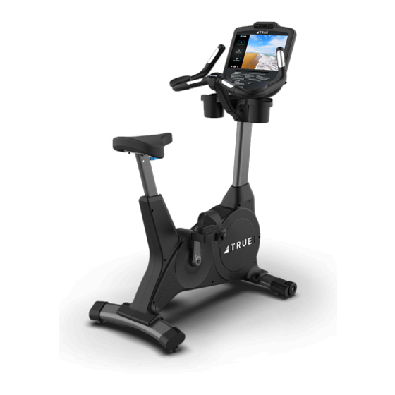
Page 30: Chapter 3: Product Overview
CHAPTER 3: PRODUCT OVERVIEW BIKE OVERVIEW: Console Assembly Contact Heart Rate Pads Seat Adjustment Handle Bottle Holder Pedals Battery Charge Port Coaxial Port Ethernet Port Power Cord Leveling Feet Truefitness.com / 800.426.6570 / 636.272.7100... - Page 31 CHAPTER 3: PRODUCT OVERVIEW BIKE OVERVIEW (continued): Console Assembly: The console allows the user to set up a workout program and control the bike during a workout (For console overview and operation instructions refer to the owner’s manual for the selected console option). Contact Heart Rate Pads: Allows the user to check their heart rate without wearing a wireless chest strap.
-
Page 32: Chapter 4: Care & Maintenance
It is important to perform the minor maintenance tasks described in this section. Failure to maintain the bike as described here could void the TRUE Fitness Warranty. To reduce the risk of electrical shock, always unplug the unit from its power source before cleaning or performing any maintenance tasks. -
Page 33: Other Scheduled Preventive Maintenance
CHAPTER 4: CARE & MAINTENANCE OTHER SCHEDULED PREVENTIVE MAINTENANCE: TRUE recommends that yearly scheduled maintenance to be performed by a qualified service technician. Please contact your dealer or visit www.truefitness.com to contact a local TRUE authorized service technician. Scheduled Preventive Maintenance: •... -
Page 34: Chapter 5: Customer Service
HOURS OF OPERATION: 8:30 A.M. - 5:00 P.M. CST E-MAIL: service@truefitness.com CONTACTING SALES: Interested in TRUE Products? Please contact us with any sales or product inquires so that we may direct you to the appropriate sales representative to answer your questions. TRUE FITNESS HOME OFFICE 865 HOFF ROAD ST. -
Page 35: Reporting Freight Claims Or Parts Damage
Severe Damage: Obvious damage to external packaging / internal product. Please refuse the shipment and it will be returned to TRUE Fitness by the carrier. Contact the TRUE Fitness customer support team by calling 800.883.8783 or sales support team by calling 800.426.6570 Monday-Friday during normal business hours to notify us that the shipment has been refused. -
Page 36: Chapter 6: Additional Information
This troubleshooting guide is intended to assist in diagnostics only and is not all inclusive. Technical specifications, error codes and programming are subject to change without notice. TRUE accepts no liability for any damage or loss suffered by persons whom rely wholly or in part on any description or statement contained within this manual. Please visit www.TRUEfitness.com to obtain the most recent version of all manuals and contact the TRUE Service Department at 800-... - Page 37 Corrupted brainboard Corrupted Re-install Console configuration - fails integrity Firmware and software Console software/firmware check versions are not Configuration Contact dealer or TRUE compatible service Power cycle Console Configure incorrectly Re-configure console Fault CN01: Re-install Console Math error - software...
- Page 38 CHAPTER 6: ADDITIONAL INFORMATION TROUBLESHOOTING GUIDE (CONTINUED): Fault CN03: Membrane Key stuck Membrane key is Contact dealer or TRUE Console Stuck Key down/closed damaged service Power cycle Loose Cable Fault CN04: Check cable connections Lower Board Brainboard fails to receive timely...
-
Page 39: Warranty Information
Product. The frame is warranted for labor and freight (for parts the Product was purchased is no longer an authorized TRUE shipped from TRUE) for two years from date of purchase. * This dealer, then TRUE Limited Warranty service may be obtained... - Page 40 UC400 UPRIGHT BIKE SERIAL NUMBERS: Registration Form is completed on-line; or if the attached form is filled in, signed by the original purchaser and mailed to TRUE within 30 days of purchaser’s receipt of this Product. The serial The UC400 upright bike comes with two serial numbers; one on number must be intact on the Product for this Limited Warranty the base and one on the display console (see diagram below).
- Page 41 UC400 Upright Bike Thank you for purchasing a TRUE product. To validate the TRUE product warranty the fast and easy way, please go on-line now to truefitness.com/support and register your product. The information you provide will never be distributed to any other individuals or agencies for any purpose.
Need help?
Do you have a question about the UC400 and is the answer not in the manual?
Questions and answers