Table of Contents
Advertisement
Quick Links
Advertisement
Table of Contents

Related Manuals for True UC900-20


Summary of Contents for True UC900-20
- Page 1 UC900 UPRIGHT BIKE OWNER’S MODEL UC900-20 MANUAL (MAN-UC900-20 REV00)
- Page 4 Alle hier gezeigten Produkte sind Prototypen. Das tatsächliche Produkt ausgeliefert wird, kann variieren. Produkt- Spezifi kationen, Funktionen und Software können sich ohne vorherige Ankündigung ändern. In den meisten Fällen bis zu Bedienungsanleitung Bisher besuchen und für Dokumente in weiteren Sprachen fi nden Sie unter https://truefi tness.com/ support/user-manuals/ BELANGRIJK! Alle getoonde producten zijn prototype.
- Page 5 You can count on TRUE Fitness for the best service in the industry, provided by a team focused on optimizing the life of your equipment.
- Page 6 You may receive a shipment that looks intact and discover once the box has been opened that there are hidden damages. Please notify the carrier immediately. TRUE will not be able to fi le a claim if the carrier is not notifi ed in a timely manner.
-
Page 7: Table Of Contents
TABLE OF CONTENTS SAFETY INSTRUCTIONS IMPORTANT SAFETY INSTRUCTIONS—SAVE THESE INSTRUCTIONS................8 *POWER REQUIREMENTS*..............................10 PROPER TRAINING POSITION ............................11 SPACE REQUIREMENTS..............................11 SPECIFICATIONS..................................12 WARNING DECALS................................12 COMPLIANCES..................................12 ASSEMBLY INSTRUCTIONS PRE-ASSEMBLY CHECKLIST.............................13 ASSEMBLY STEPS................................17 PRODUCT OVERVIEW PRODUCT FEATURES................................36 CARE AND MAINTENANCE INSPECTION..................................37 CLEANING THE EQUIPMENT.............................37 LUBRICATION.............................37 LEVELING THE MACHINE..............................38 PREVENTATIVE MAINTENANCE............................39 LONG TERM STORAGE..............................39... -
Page 8: Safety Instructions
• Replace warning labels that may be worn, damaged, • TRUE STRONGLY recommends seeing a physician or missing. for a complete medical exam before undertaking an exercise program, particularly if the user has a family •... - Page 9 Do not reach into or underneath the unit, or tip it on product. its side during operation. • Never operate a TRUE product if it has a damaged • Do not use if you have a cold or fever. power cord or electrical plug, or if it has been dropped, damaged, or even partially immersed in •...
-
Page 10: Power Requirements
*POWER REQUIREMENTS* Read and understand all instructions before plugging any TRUE power cord into an electrical outlet. *Power warnings, grounding instructions, and power requirements are only applicable when this product is being used with the optional power supply.* NOTE: The Envision II 16” and ShowRunner II consoles require the optional power supply. -
Page 11: Proper Training Position
SPACE REQUIREMENTS TRUE recommends leaving a minimum of 24” (61cm) on each side of the equipment and a 39” (99 cm) safety zone at the rear of the equipment. -
Page 12: Specifications
143 lbs / 65 kg WARNING DECALS WARNING: Replace warning labels that may be worn, damaged, or missing. To replace any worn or missing decals contact TRUE product support (service@truefi tness.com // 800.883.8783). console serial Model No. number location UC900-20 Serial No./Date Code... -
Page 13: Assembly Instructions
Unpacking and assembling of this product is a two person task. VERIFY BOX CONTENTS IMPORTANT! Please verify box contents. If you have questions, or if there are any missing parts, contact product support (service@truefi tness.com // 800.883.8783). TOOLS NEEDED FOR INCLUDED... - Page 14 BOX CONTENTS ITEM DESCRIPTION Base Left Pedal Right Pedal Seat Saddle Storage Tray Rear Console Cover Handlebar Front Console Cover Left Cup Holder Right Cup Holder Front Mast Mast Boot Front Stabilizer Rear Stabilizer Hardware Bag(s) Manual...
- Page 15 HARDWARE CONTENTS Front and Rear Stabilizer Hardware Front Mast Hardware ITEM DESCRIPTION ITEM DESCRIPTION SCREW M8X20L (E. COATING) SCREW M8X70L (E. COATING) UCS0061 UCS0309 SPRING WASHER M8 (E. COATING) SPRING WASHER M8 (E. CS80156 COATING) CS80156 WASHER, M8X16X1.2T, BLACK WASHER, M8X16X1.2T, BLACK CBW0015 CBW0015 Handlebar Hardware...
- Page 16 HARDWARE CONTENTS Tools ITEM DESCRIPTION 6MM BALL END ALLEN WRENCH 13MM/15MM/17MM COMBINATION WRENCH...
-
Page 17: Assembly Steps
ASSEMBLY STEPS STEP 1—ATTACH REAR STABILIZER Parts Used in this Step Tools Used in this Step PART DESCRIPTION 6mm Ball End Allen Wrench UCS0309 SCREW M8X70L (E. COATING) CS80156 SPRING WASHER M8 (E. COATING) CBW0015 WASHER, M8X16X1.2T, BLACK UCS0033BK SUBASSEMBLY, STABILIZER, REAR 1. - Page 18 STEP 2—ATTACH FRONT STABILIZER Tools Used in this Step Parts Used in this Step 6mm Ball End Allen PART DESCRIPTION Wrench UCS0309 SCREW M8X70L (E. COATING) CS80156 SPRING WASHER M8 (E. COATING) CBW0015 WASHER, M8X16X1.2T, BLACK UCS0015BK SUBASSEMBLY, FRONT STABILIZER 1.
- Page 19 STEP 3—ATTACH SEAT SADDLE Tools Used in this Step Parts Used in this Step 13mm/15mm/17mm PART DESCRIPTION Combination Wrench UCS0367 NUT, NYLOCK, M8, BLACK CBW0015 WASHER, M8X16X1.2T, BLACK BZU0009 SUBASSEMBLY, SEAT BOTTOM CUSHION (SADDLE) 1. Using the 13mm end of the 13mm/15mm/17mm combination wrench, remove the preassembled nuts and washers from the 3 threaded rods on the bottom of the seat saddle.
- Page 20 OPTIONAL STEP 4—INSTALL AUXILIARY POWER SUPPLY Tools Used in this Step Parts Used in this Step #2 Phillips Screwdriver PART DESCRIPTION UCS0363 SCREW, M4 X 35L, BLACK UCS0028BK COVER, POWER SUPPLY ACCESS 00560402 POWER CORD, FUYANG Wire cutters 00595500 POWER SUPPLY, FUYANG 12V 6A IMPORTANT! These steps are only required if this unit is paired with the Envision II 16”...
- Page 21 OPTIONAL STEP 4—INSTALL AUXILIARY POWER SUPPLY CONTINUED 00595500 00560402 00595500 00560402 00595500...
- Page 22 OPTIONAL STEP 4—INSTALL AUXILIARY POWER SUPPLY CONTINUED UCS0028BK UCS0363...
- Page 23 STEP 5—ROUTE FRONT MAST CABLES Parts Used in this Step PART DESCRIPTION UCS0318BK SUBASSEMBLY, UC900 CONSOLE MAST UCS0007BK SUBASSEMBLY, CONSOLE MAST BOOT W/ GASKET 1. Slide the mast boot up the front mast. 2. Pull the cables coming from the front of the bike through the front mast using the provided pull tie. 3.
- Page 24 STEP 6—ATTACH FRONT MAST Tools Used in this Step Parts Used in this Step 6mm Ball End Allen PART DESCRIPTION Wrench UCS0061 SCREW M8X20L (E. COATING) CS80156 SPRING WASHER M8 (E. COATING) CBW0015 WASHER, M8X16X1.2T, BLACK UCS0318BK SUBASSEMBLY, UC900 CONSOLE MAST Using a 6mm ball end allen wrench, secure the front mast to the bike frame using 6 screws, 6 spring washers, and 6 fl...
- Page 25 STEP 7—ATTACH MAST BOOT Tools Used in this Step Parts Used in this Step #2 Phillips Screwdriver PART DESCRIPTION UCS0304 SCREW M5X10L,BLACK UCS0318BK SUBASSEMBLY, UC900 CONSOLE MAST UCS0007BK SUBASSEMBLY, CONSOLE MAST BOOT W/ GASKET 1. Pull the mast boot down onto the plastic shrouds at the bottom of the console mast. 2.
- Page 26 STEP 8—ROUTE HANDLEBAR CABLES While one person holds the handlebar securely in place, route the handlebar cables through the front mast.
- Page 27 STEP 9—ATTACH HANDLEBAR Tools Used in this Step Parts Used in this Step 6mm Ball End Allen PART DESCRIPTION Wrench FT0047 SHCS, M8 X P1.25 X 20MM CS80156 SPRING WASHER M8 (E. COATING) CS80157 WASHER, FLAT, 8MM X 16MM X 1.2MM, E COAT UCS0381BK SUBASSEMBLY, HANDLEBAR, UC900...
- Page 28 STEP 10—CONNECT HEART RATE MONITOR CABLES 1. Unwrap the handlebar cable bundle and retrieve the left and right heart rate monitor cables. 2. Retrieve the four pin heart rate cable from the front mast cable bundle. 3. Insert the heart rate cables into both ends of the nucleus board on the console mounting plate as shown below. 4.
- Page 29 STEP 11—ATTACH STORAGE TRAY Tools Used in this Step Parts Used in this Step #2 Phillips Screwdriver PART DESCRIPTION TL0064 PRHMS M5-0.8x8 BLACK UCS0025BK SUBASSEMBLY, IPOD TRAY W/CUP HOLDER Using a #2 Phillips screwdriver, attach the storage tray to the mounting plate using 4 screws. UCS0025BK TL0064...
- Page 30 STEP 12—ATTACH PEDALS Tools Used in this Step Parts Used in this Step 13mm/15mm/17mm PART DESCRIPTION Combination Wrench RB0076BK SUBASSEMBLY, PEDAL SET W/STRAP Torque Wrench with 15mm Head 1. Using the 15mm end of the 13mm/15mm/17mm combination wrench, attach each pedal to its corresponding crank. 2.
- Page 31 STEP 13—ATTACH CONSOLE TO FRONT MAST Tools Used in this Step Parts Used in this Step #2 Phillips Screwdriver PART DESCRIPTION CONSOLE UCS0318BK SUBASSEMBLY, UC900 CONSOLE MAST 1. Using a #2 Phillips screwdriver, secure the console to the console mast using the hardware pre-assembled to the console (00567800 // SCREW, M5-.8X12 COMBO PHILLIPS/COMMON TRUSS HEAD - ACG BLACK // QTY 4).
- Page 32 STEP 14—ATTACH FRONT AND REAR CONSOLE COVERS Parts Used in this Step Tools Used in this Step PART DESCRIPTION #2 Phillips Screwdriver CS80131 SCREW M5X15L (BLACK) TL0045 SCREW M5*20L (BLACK) UCS0006BK COVER, CONSOLE, FRONT UCS0031BK SUBASSEMBLY, REAR CONSOLE COVER 1. Using a #2 Phillips screwdriver, attach the front console cover to the front mast using 1 of the 4 shorter screws. NOTE: Be sure that the front console cover aligns with the storage tray around the handlebar.
- Page 33 STEP 15—ATTACH CUP HOLDERS Parts Used in this Step PART DESCRIPTION UCS0010LBK HOLDER, CUP, LEFT UCS0010RBK HOLDER, CUP, RIGHT Insert each cup holder into its corresponding place on the storage tray as shown below. UCS0010RBK UCS0010LBK...
- Page 34 STEP 16—LEVEL THE MACHINE Tools Used in this Procedure 13mm/15mm/17mm Combination Wrench 1. Using the 13mm end of the 13mm/15mm/17mm combination wrench, adjust all four leveling feet until they contact the fl oor. IMPORTANT! Do not adjust the leveling feet to such a height that they detach or unscrew from the machine. 2.
- Page 35 OPTIONAL STEP 17—ATTACH POWER CORD Parts Used in this Step PART DESCRIPTION UCS0029BK SUBASSEMBLY, INLET, POWER SUPPLY 00560402 POWER CORD, 110V 00687000 POWER CORD, 220V IMPORTANT! This step is only required if this unit is paired with the Envision II 16” or ShowRunner II consoles. Insert the appropriate power cord into the corresponding power inlet.
-
Page 36: Product Overview
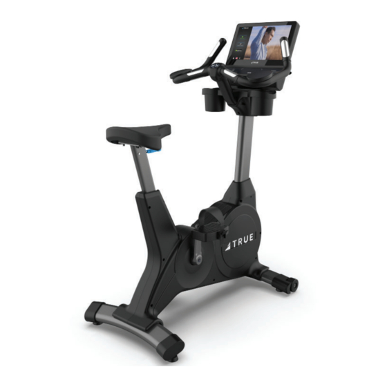
PRODUCT OVERVIEW PRODUCT FEATURES Contact Heart Rate Pads Quick Access Keys Console Handlebar Bottle Holders L E VE L Seat Adjustment Seat Handle Coaxial Port, Ethernet Port, and Power Supply Inlet Leveling Feet Console Pedals Allows the user to set up a workout program and control Moving part of the bike that provides resistance to the the bike during a workout. -
Page 37: Care And Maintenance
It is important to perform the minor maintenance tasks described in this section. Failure to maintain the bike as described here could void the TRUE Fitness Warranty. *To reduce the risk of electrical shock, always unplug the unit from its power source before cleaning or performing any maintenance tasks.*... -
Page 38: Leveling The Machine
LEVELING THE MACHINE CAUTION: Prevent potential damage to the machine and injury to the user. This unit is equipped with four leveling feet. Make sure that the bike is level at all times. If the bike is placed on a uneven surface, adjusting the leveling feet can help, but may not completely compensate for extremely uneven surfaces. -
Page 39: Preventative Maintenance
PREVENTATIVE MAINTENANCE TRUE recommends that quarterly scheduled maintenance be performed by a qualifi ed service technician. Please contact your dealer or visit www.truefi tness.com to contact a local TRUE authorized service technician. IMPORTANT! Use only TRUE Fitness certifi ed service providers. -
Page 40: Additional Information
This troubleshooting guide is intended to assist in diagnostics only and is not all inclusive. Technical specifi cations, error codes and programming are subject to change without notice. TRUE accepts no liability for any damage or loss suff ered by persons whom rely wholly or in part on any description or statement contained within this manual. Please visit www.truefi... - Page 41 (ATCS), digital cable (QAM) Channels or format type not correct Rescan TV channels Tuner Invalid Contact TRUE Product Support Transmitter belt contacts are not making good contact Re-adjust the transmitter belt so that it is in full contact with with the skin...
- Page 42 Corrupted brainboard confi guration Console Console Confi guration - fails integrity check Re-install software/fi rmware Firmware and software versions are not compatible Contact TRUE Product Support Power cycle Console Confi gure Incorrectly Re-confi gure console Fault CN01: Internal Fault Console Math error - software Re-install software/fi...
-
Page 43: Uc900 Wiring Diagram (Optional Auxiliary Power Supply)
UC900 WIRING DIAGRAM (OPTIONAL AUXILIARY POWER SUPPLY) CONSOLE HANDLEBAR UCS0381BK UCS0021 Thumbswitches UC0004 UCS0063 Thumbswitches UCS0021 Heart Rate Right UC0007 BATTERY Heart Rate Left UC0007 00588800 COMBO LOWER CONTROL BOARD HEART RATE 00591500 CHARGING BOARD PORT 00614200 UCS0374 NUCLEUS BOARD UCS0001 00612700 UCS0026... -
Page 44: Uc900 Wiring Diagram (Self-Generating Power)
UC900 WIRING DIAGRAM (SELF-GENERATING POWER) CONSOLE HANDLEBAR UCS0381BK UCS0021 Thumbswitches UC0004 UCS0063 Thumbswitches UCS0021 Heart Rate Right UC0007 BATTERY Heart Rate Left UC0007 00588800 COMBO LOWER CONTROL BOARD HEART RATE 00591500 CHARGING BOARD PORT 00614200 UCS0374 NUCLEUS BOARD UCS0001 00612700 UCS0026 UC0003 UC0001... -
Page 45: Warranty Information
*This limited warranty on the structural frame does not purchaser and the parts of the TRUE product (the include paint or coatings. The frame is defi ned as the “Product”) listed below, under normal use and service,... -
Page 46: Uc900 Bike Residential Limited Warranty
*This limited warranty on the structural frame does not purchaser and the parts of the TRUE product (the include paint or coatings. The frame is defi ned as the “Product”) listed below, under normal use and service,... - Page 47 UC900 BIKE LIMITED WARRANTY Save Time and Register Online! Activate Multiple Warranties at truefi tness.com THE TRUE LIMITED WARRANTY IS SUBJECT TO AND WILL BE IN ACCORDANCE WITH THE CONDITIONS SET FORTH BELOW: This limited warranty is valid for the United States and 14.
- Page 48 UC900 BIKE LIMITED WARRANTY Save Time and Register Online! Activate Multiple Warranties at truefi tness.com KEEP THIS PAGE FOR YOUR RECORDS SERIAL NUMBERS: The product comes with two serial numbers; one on the base and one on the console. The serial number on the base is under the rear stabilizer.
- Page 49 Activate Multiple Warranties at truefi tness.com Thank you for purchasing a TRUE product. To validate the TRUE product warranty the fast and easy way, please go on- line now to truefi tness.com and register your product. The information you provide will never be distributed to any other individuals or agencies for any purpose.
- Page 52 T R U E F I T N E S S . C O M I N T E G R I T Y M A T T E R S TRUE Fitness Technology, Inc | 865 Hoff Road, St. Louis, MO 63366 © 2023 TRUE. All Rights Reserved.
Need help?
Do you have a question about the UC900-20 and is the answer not in the manual?
Questions and answers