True ES700 Owner's Manual
Hide thumbs
Also See for ES700:
- Owner's manual (65 pages) ,
- Owner's manual (46 pages) ,
- Owner's manual (44 pages)

Related Manuals for True ES700


Summary of Contents for True ES700
- Page 1 *Assembly Guide & Warranty Card Included ES700 RECUMBENT BIKE OWNER’S MANUAL Revision 122313...
- Page 2 ES700 RECUMBENT BIKE OWNERS MANUAL IMPORTANT: All Products shown are prototype. Actual product delivered may vary. Product specifications, features & software are subject to change without notice. For the most up to date owner’s manual please visit www.truefitness.com. For documents in additional languages please visit www.truefitness.com/document-library/29/international-manuals IMPORTANTE: Todos los productos mostrados son prototipos.
- Page 3 The proud manufacturing tradition of quality and the culture of innovation at TRUE have given rise to a full line of truly extraordinary treadmills, indoor cycles and elliptical cross-trainers. As a result, people all over the world are benefiting from the TRUE experience.
-
Page 4: Table Of Contents
ES700 RECUMBENT BIKE OWNERS MANUAL TABLE OF CONTENTS : Chapter 1: Safety Instructions Chapter 4B: Emerge Operation Safety Instructions Emerge Overview & Navigation Space Requirements Advanced Console Functions Grounding Instructions Power Requirements Chapter 5: Care & Maintenance Warning Decals Care & Maintenance... -
Page 5: Chapter 1: Safety Instructions
45, smokes, has high cholesterol, is obese or has not exercised regularly in the past year. Additionally, TRUE recommends consulting a fitness professional on the correct use of this product. - Page 6 Do not use this product outdoors, near water, while wet, or in areas if high humidity including extreme temperature changes • Never operate a TRUE product with the air openings blocked. Keep air openings free of lint, hair or any obstructing material. •...
-
Page 7: Space Requirements
Cleaning and user maintenance shall not be made by children without supervision. SPACE REQUIREMENTS: • TRUE’s recommendation is to leave a 39” safety zone at rear of bike. The sides of the bike should be at least 20” away from the wall or obstructions. (See Fig 1) GROUNDING INSTRUCTIONS: This product must be grounded, if it should malfunction or breakdown, grounding provides a path of least resistance for electric current to reduce the risk of electric shock. - Page 8 CHAPTER 1: SAFETY INSTRUCTIONS GROUNDING INSTRUCTIONS (continued): DANGER Improper connection of the equipment-grounding conductor can result in a risk of electric shock. • Check with a qualified electrician or serviceman if you are in doubt as to whether the product is properly grounded. Do •...
-
Page 9: Power Requirements
CHAPTER 1: SAFETY INSTRUCTIONS Truefitness.com / 800.426.6570 / 636.272.7100... -
Page 10: Warning Decals
CHAPTER 1: SAFETY INSTRUCTIONS WARNING DECALS: WARNING: Replace warning labels that may be worn, damaged or missing. To replace any worn or missing warning decals contact TRUE FITNESS by one of the following: www.truefitness.com contact customer service at 800-883-8783. COMPLIANCES: This equipment complies with all applicable codes and regulations. -
Page 11: Chapter 2: Assembly Instructions
All exercise equipment is potentially hazardous. If attention is not paid to the conditions of equipment usage, death, or serious injury could occur. • Save these instructions. *Should you need technical assistance in assembly of your TRUE Fitness product, contact TRUE Fitness Technical Support at 1-800-883-8783. PRE-ASSEMBLY CHECK LIST: Provided Tools:... - Page 12 CHAPTER 2: ASSEMBLY INSTRUCTIONS PRE-ASSEMBLY CHECK LIST (continued): Provided hardware: 1 & 2 (F & R 4 (S RONT TABILIZER ANDLEBAR Counter-bore Hex Screw, M8xL20 Hex Screw, M10xL55 (C4) Qty. 4 (X1) Qty. 4 Hex Screw, M8xL20 (X4) Qty. 2 Split Washer, M10 (S1) Qty.
- Page 13 CHAPTER 2: ASSEMBLY INSTRUCTIONS PRE-ASSEMBLY CHECK LIST (continued): Additional Items Provided: POLAR T34 Transmitter and Chest Strap (Heart Rate Monitor) Power Adaptor NOTE: For the 9” TFT Console, a different 12V, 3A Power Adaptor is provided with the console packaging. NOTE: For the Orange LED Console, use the 9V, 1.5A Power Adapter provided with the base unit Truefitness.com / 800.426.6570 / 636.272.7100...
-
Page 14: Assembly Steps
CHAPTER 2: ASSEMBLY INSTRUCTIONS ASSEMBLY STEPS: CAUTION: • Use caution when assembling bike. It is recommended that at least two people unpack and assemble bike. • Remove all bike components from packaging. • For each step use hardware in the corresponding bag Sub-Assembly Identification: Use the image below as a reference for where the provided sub-assemblies will be located in the complete bike assembly: Truefitness.com / 800.426.6570 / 636.272.7100... - Page 15 CHAPTER 2: ASSEMBLY INSTRUCTIONS ASSEMBLY STEPS (continued): Step 1 & 2 Front and Rear Stabilizer Bars: CAUTION: • It is recommended that at least 2 people are used to assemble the bike • To protect the floor from damage, rest the bike frame on a large piece of cardboard packaging •...
- Page 16 CHAPTER 2: ASSEMBLY INSTRUCTIONS ASSEMBLY STEPS (continued): Step 3 Seat Handlebar Cable Connections: • Prior to connection, verify the handlebar is in the correct orientation; graphics on the contact heart rate thumb switches should be facing up • Connect the handlebar cables, as shown by the connection lines in the provided diagrams (above, left) Step 4 Seat Handlebar Assembly: •...
- Page 17 CHAPTER 2: ASSEMBLY INSTRUCTIONS ASSEMBLY STEPS (continued): Step 5 Seat Back Frame Assembly: • Install the seat back frame into the seat carriage • For each hex screw (X5, quantity 8), install through quantity 1 split washer (S5), followed by quantity 1 flat washer (F5) •...
- Page 18 CHAPTER 2: ASSEMBLY INSTRUCTIONS ASSEMBLY STEPS (continued): Step 6 Rear Seat Pivot Cover Assembly: • Install the rear seat pivot cover onto the seat carriage; rear seat pivot cover should mate cleanly with the front seat pivot cover (as shown in diagram, above) •...
- Page 19 CHAPTER 2: ASSEMBLY INSTRUCTIONS ASSEMBLY STEPS (continued): Step 8 Pedal Assembly: • Align the left pedal with the left crank, and the right pedal with the right crank (pedals should be clearly labeled on the pedal strap) • Secure each pedal to the appropriate crank using the provided pedal wrench NOTE: The left pedal is reverse-threaded...
- Page 20 CHAPTER 2: ASSEMBLY INSTRUCTIONS ASSEMBLY STEPS (continued): Step 10 Front Mast Cable Connections: • At least 1 person should hold the front mast while an additional person(s) routes the front mast cables • Route the bundle of cables through the front mast, as shown in the provided image (left) •...
- Page 21 CHAPTER 2: ASSEMBLY INSTRUCTIONS ASSEMBLY STEPS (continued): Step 12 Media Holder • Align the media holder thru holes (quantity 2) with the front mast thru holes (quantity 2); verify that the media holder is in the correct orientation (as shown in diagram, above) •...
- Page 22 CHAPTER 2: ASSEMBLY INSTRUCTIONS ASSEMBLY STEPS (continued): Step 13 Console Cable Connections: Orange LED Console NOTE: Ethernet cable connection is not available on the Orange LED Console Truefitness.com / 800.426.6570 / 636.272.7100...
- Page 23 CHAPTER 2: ASSEMBLY INSTRUCTIONS ASSEMBLY STEPS (continued): Step 13 Console Cable Connections (continued): 9” TFT Console NOTE: Ethernet cable connection is not available on the 9” TFT Console. NOTE: For the 9” TFT Console, it is important that the 12V, 3A Power Adaptor is installed. Truefitness.com / 800.426.6570 / 636.272.7100...
- Page 24 CHAPTER 2: ASSEMBLY INSTRUCTIONS ASSEMBLY STEPS (continued): Step 14 Console Ground Connection: • Locate the ground screw; pre-installed into the grounding hole on the front mast console bracket • Remove the ground screw with a Phillips Head screwdriver (not provided) •...
- Page 25 CHAPTER 2: ASSEMBLY INSTRUCTIONS ASSEMBLY STEPS (continued): Unit Leveling (if necessary): Turn feet (4x, located on the front and rear stabilizer) to adjust the levelness of the unit. Final Unit Connections: NOTE: For the 9” TFT Console, it is important that the 12V, 3A Power Adaptor is installed Truefitness.com / 800.426.6570 / 636.272.7100...
- Page 26 CHAPTER 2: ASSEMBLY INSTRUCTIONS ASSEMBLY STEPS (continued): Seat Bottom Adjustment (if necessary): The following information discusses the adjustability of the seat bottom position relative to the mesh seat back. Threaded seat bottom holes used for the “Back” position “Back” position The default seat bottom position is towards the back, creating a minimal amount of space between the seat bottom and the mesh seat back.
-
Page 27: Chapter 3: Product Overview
CHAPTER 3: PRODUCT OVERVIEW BIKE OVERVIEW: Console Assembly Contact Heart Rate Pads Quick Access Keys Bottle Holder Power Cord Seat Adjustment Pedals Leveling Feet Truefitness.com / 800.426.6570 / 636.272.7100... -
Page 28: Bottle Holder
CHAPTER 3: PRODUCT OVERVIEW BIKE OVERVIEW (continued): Console Assembly: The console allows the user to set up a workout program and control the bike during a workout (For console overview and operation instructions refer to the owner’s manual for the selected console option). Contact Heart Rate Pads: Allows the user to check their heart rate without wearing a wireless chest strap. -
Page 29: Chapter 4: Programming & Operation Heart Rate Monitoring
HEART RATE CONTROL (HRC): Introduction: You are now the owner of the most sophisticated Heart Rate Control equipment available. TRUE HRC is unique and patented. It accommodates users from rehabilitation to world class athletes, and all those in between. TRUE HRC allows users to do a completely adjustment free heart rate controlled workout. -
Page 30: Target Heart Rate
HEART RATE CONTROL (continued): The TRUE HRC system is unique because users must enter the key parameters of the workout; target heart rate, weight, age, and time, prior to beginning the HRC workout. As users approach their target heart rate, the bike’s computer takes full control over the workout and changes the workout intensity automatically to keep users near their target heart rate. -
Page 31: Program Descriptions
CHAPTER 4: PROGRAMMING & OPERATION PROGRAM DESCRIPTIONS: Available programs vary depending on the console option selected. Please refer to the chart below for assistance in determining which programs are available on this unit. Console Options Escalate Emerge Quick Start: ** A workout in which the user controls all settings. -
Page 32: Calorie Goal
CHAPTER 4: PROGRAMMING & OPERATION PROGRAM DESCRIPTIONS (continued): Glute Buster: * A changing WORKLOAD profile simulates hilly terrain to promote intense glute muscle use. Calorie Goal: ** This workout allows users to choose the number of calories they wish to burn within a specified workout time. The WORKLOAD will adjust automatically to attain this goal. - Page 33 CHAPTER 4: PROGRAMMING & OPERATION PROGRAM DESCRIPTIONS (continued): Target HRC: ** Users choose their target heart rate. The workout begins in MANUAL control – users should gradually increase the WORKLOAD until therir heart rate is within 10 bpm of their target. At this point, the machine takes control of WORKLOAD to maintain the user’s HR within a few beats of their target.
-
Page 34: Chapter 4A: Escalate 9 Operation
CHAPTER 4A: ESCALATE OPERATION ESCALATE OVERVIEW: LCD Display Selection Buttons Selection Buttons Decrease Increase Workload Workload Start Stop Reading Warning Rack USB Port Numeric Headphone 30 Pin iPod® Decal Keypad Jack Connector Truefitness.com / 800.426.6570 / 636.272.7100... -
Page 35: Escalate 9 Overview
CHAPTER 4A: ESCALATE OPERATION ESCALATE OVERVIEW (continued): LCD Display: Used to monitor or control a work out and for feature navigation. Selection Buttons: Used to navigate menus and make selections via the LCD Display. Workload Keys: Manually increases or decreases the workout intensity. Start: Allows the user to begin a Quick Start workout or preset workout. -
Page 36: Console Navigation
CHAPTER 4A: ESCALATE OPERATION CONSOLE NAVIGATION: Home Screen: The Home Screen is displayed on the console when there is no workout in progress. From this screen the user is able to select from various options to begin a workout. A) Workout Finder Displays preset workouts categorized by goal focused categories. - Page 37 CHAPTER 4A: ESCALATE OPERATION CONSOLE NAVIGATION (continued): Selecting a Preset Workout: Preset workouts are accessed by selecting Workout Finder from the home screen. To view the workouts in a category, select the category (A) by using the Scroll Selection Buttons (B) and then press the Next Selection Button (C). *Press and hold the Next Selection Button to return to the previous screen.
- Page 38 CHAPTER 4A: ESCALATE OPERATION CONSOLE NAVIGATION (continued): Workout Data Screens: During any workout a Workout Data Screen will be displayed to give the user a comprehensive visual overview of their current workout data. A) Custom Data Display #1: By Default, this display will show the distance for the current workout. Users can also choose custom data points to be seen in this display.
- Page 39 CHAPTER 4A: ESCALATE OPERATION CONSOLE NAVIGATION (continued): Workout Data Screen Controls: The Workout Data Screens contain various controls that allow users to adjust workout settings and to customize their overall workout experience. These controls are accessed by pressing the Selection Button for the control they wish to use. A) Change View: Switches between the available Workout Data Screens.
- Page 40 CHAPTER 4A: ESCALATE OPERATION CONSOLE NAVIGATION (continued): D) Source: Toggles iPod® on or off (when connected via the 30 pin iPod® connector), When an audio source is selected the user is given control over volume adjustments (A) and the ability to skip tracks (B). E) Show Tools: Pressing the Show Tools Selection Button (A) will display various options.
- Page 41 CHAPTER 4A: ESCALATE OPERATION CONSOLE NAVIGATION (continued): F) Bike Mode: Engages Bike Mode, which simulates riding a 21-speed road bike. The resistance changes to constant torque against the pedals and calculates speed (A) for a more realistic biking experience. Using the Workload Keys (B) will change the simulated gears (C).
-
Page 42: Advanced Console Functions
CHAPTER 4A: ESCALATE OPERATION ADVANCED CONSOLE FUNCTIONS: Entering Service Mode: Entering Service Mode can be completed by pressing and holding the upper left selection button (A) for 3-5 seconds or until the “Workout Finder” icon (B) blinks. When the “Workout Finder” icon blinks, release the upper right selection button and hold the “Workout Finder”... -
Page 43: Truefitness.com / 800.426.6570 / 636.272.7100
CHAPTER 4A: ESCALATE OPERATION ADVANCED CONSOLE FUNCTIONS (continued): Summary Screen: The Summary Screen provides an overview of the unit’s current settings (values cannot be changed in this screen). A) Product Model: The model number that the console is currently configured to. B) Software Version: The current version of software that is installed on the console. -
Page 44: Truefitness.com / 800.426.6570 / 636.272.7100
CHAPTER 4A: ESCALATE OPERATION ADVANCED CONSOLE FUNCTIONS (continued): Utilities Menu: The Utilities Menu allows users to adjust the time and date settings. Press the Enter Selection Button (A) to the time and date. Setting Time and Date: Use the Previous and Next Selection Buttons (A) to highlight the field to be changed. Then use the adjustment selection buttons (B) to adjust the selected value. -
Page 45: Truefitness.com / 800.426.6570 / 636.272.7100
CHAPTER 4A: ESCALATE OPERATION ADVANCED CONSOLE FUNCTIONS (continued): Demo Mode: Demo mode is intended for use by sales professionals and should not be used in a home environment Diagnostics Menu: The Diagnostics menu will display the unit’s current usage data including total distance, in miles, that the unit has traveled as well as the total time, in hours, that the unit has been in use. -
Page 46: Truefitness.com / 800.426.6570 / 636.272.7100
CHAPTER 4A: ESCALATE OPERATION ADVANCED CONSOLE FUNCTIONS (continued): Options Menu: The options menu contains 5 Settings with various options available for each. To navigate the options menu, use the scroll selection buttons (A) to highlight the option to be changed (B) and use the + and - Selection Buttons (C) to adjust the options. -
Page 47: Chapter 4B: Emerge Operation
CHAPTER 4B: EMERGE OPERATION EMERGE OVERVIEW & NAVIGATION: Upper LED Upper LED HRC Cruise Display Displays Numeric Keypad Control Decrease Increase Workload Workload Start Workout Change Enter Reading Warning Target Finder Display Rack Decal Truefitness.com / 800.426.6570 / 636.272.7100... - Page 48 CHAPTER 4B: EMERGE OPERATION EMERGE OVERVIEW & NAVIGATION (continued): Workload Keys: Manually increases or decreases the workout intensity. Start: Allows the user to begin a Quick Start workout or preset workout. Workout Finder: Pressing this button scrolls through available workouts. When the desired workout is displayed, the user must press start to begin the workout.
- Page 49 CHAPTER 4B: EMERGE OPERATION EMERGE OVERVIEW & NAVIGATION (continued): Upper LED Display: Shows the workout data of the program in progress in four value displays. Value Display Value Display Value Display Value Display Value Display #1 Value Display #2 Value Display #3 Value Display#4 Heart Rate –...
-
Page 50: Advanced Console Functions
ADVANCED CONSOLE FUNCTIONS: WARNING: Misconfiguration of the console may cause damage to the unit and void the manufacturer warranty. If necessary, please contact TRUE Fitness Technical Support at 800-883-8783 for assistance. Entering Diagnostics Mode: With the console powered up Press and hold the + WORKLOAD key for 10 seconds or until the console beeps. NOTE: If the sound is turned off no beep will be emitted from the console. -
Page 51: Chapter 5: Care & Maintenance
It is important to perform the minor maintenance tasks described in this section. Failure to maintain the bike as described here could void the TRUE Fitness Warranty. To reduce the risk of electrical shock, always unplug the unit from its power source before cleaning or performing any maintenance tasks. -
Page 52: Other Scheduled Preventive Maintenance
CHAPTER 5: CARE & MAINTENANCE OTHER SCHEDULED PREVENTIVE MAINTENANCE: TRUE recommends that yearly scheduled maintenance be performed by a qualified service technician. Please contact your dealer or visit www.truefitness.com to contact a local TRUE authorized service technician. Scheduled Preventive Maintenance: •... -
Page 53: Chapter 6: Customer Service
HOURS OF OPERATION: 8:30 A.M. - 5:00 P.M. CST E-MAIL: service@truefitness.com CONTACTING SALES: Interested in TRUE Products? Please contact us with any sales or product inquires so that we may direct you to the appropriate sales representative to answer your questions. TRUE FITNESS HOME OFFICE 865 HOFF ROAD ST. -
Page 54: Reporting Freight Claims Or Parts Damage
Severe Damage: Obvious damage to external packaging / internal product. Please refuse the shipment and it will be returned to TRUE Fitness by the carrier. Contact the TRUE Fitness customer support team by calling 800.883.8783 or sales support team by calling 800.426.6570 Monday-Friday during normal business hours to notify us that the shipment has been refused. -
Page 55: Chapter 7: Additional Information
This troubleshooting guide is intended to assist in diagnostics only and is not all inclusive. Technical specifications, error codes and programming are subject to change without notice. TRUE accepts no liability for any damage or loss suffered by persons whom rely wholly or in part on any description or statement contained within this manual. Please visit www.truefitness.com to obtain the most recent version of all manuals and contact the TRUE Service Department at 800-... - Page 56 CHAPTER 7: ADDITIONAL INFORMATION TROUBLESHOOTING GUIDE (continued): Malfunction Possible Cause Corrective Action Transmitter belt contacts are not Readjust the transmitter belt so that it is in full contact with making good contact with the the skin skin Contacts on the transmitter belt Moisten the contacts on the transmitter belt are not moist Transmitter belt is not within 3...
-
Page 57: Specification Sheet
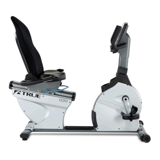
Convenient thumb controls allow quiet pedal resistance. Seat adjustment is effortless thanks to a wrap-around adjustment handle. The TRUE ES700 is the perfect mix of hard-core durability and refined comfort, inviting you to exercise. - Page 58 CHAPTER 7: ADDITIONAL INFORMATION RECUMBENT TECHNICAL Power Source 110V/15A SPECIFICATIONS Cord Length 8' (2.4M) Drive Motor Single Stage Drive System with Poly-V Belts Crank 3-Piece Forged Steel Crank System with Sealed Bearings Resistance Source Eddy Current Brake Resistance Levels 25 (Emerge), 30 (Escalate &...
-
Page 59: Warranty Information
Product. The frame is warranted for labor and freight (for parts Hours of operation 8:30am - 5:00 pm CST shipped from TRUE) for one year from date of purchase. * This limited warranty on structural frame does not include paint or The above Limited Warranty is subject to and will be in coatings. - Page 60 The ES700/ES900 bike comes with two serial numbers; one on maintenance (as referenced in the owner’s manual.) the base and one on the display console (see diagram below).
- Page 61 ES700/ES900 Bikes Thank you for purchasing a TRUE product. To validate the TRUE product warranty the fast and easy way, please go on-line now to truefitness.com/support and register your product. The information you provide will never be distributed to any other individuals or agencies for any purpose.
Need help?
Do you have a question about the ES700 and is the answer not in the manual?
Questions and answers