
Related Manuals for True RES700


Summary of Contents for True RES700
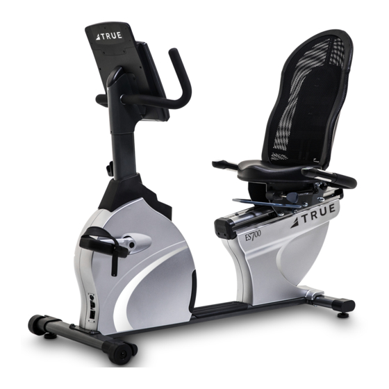
- Page 1 *Assembly Guide & Warranty Card Included RES700 RECUMBENT BIKE OWNER’S MANUAL Model # RES700-19 121718 Revision...
- Page 2 ES700 RECUMBENT BIKE OWNERS MANUAL IMPORTANT: All Products shown are prototype. Actual product delivered may vary. Product specifications, features & software are subject to change without notice. For the most up to date owner’s manual please visit www.truefitness.com. For documents in additional languages please visit www.truefitness.com/document-library/29/international-manuals IMPORTANTE: Todos los productos mostrados son prototipos.
- Page 3 The proud manufacturing tradition of quality and the culture of innovation at TRUE have given rise to a full line of extraordinary cardio and strength equipment. As a result, people all over the world are benefiting from the TRUE experience.
-
Page 4: Table Of Contents
ES700 RECUMBENT BIKE OWNERS MANUAL TABLE OF CONTENTS : Chapter 1: Safety Instructions Safety Instructions Space Requirements Grounding Instructions Power Requirements Warning Decals Compliances Chapter 2: Assembly Instructions Pre-Assembly Checklist Assembly Steps Chapter 3: Care & Maintenance Care & Maintenance Cleaning the Equipment Leveling the Unit Other Scheduled Preventive Maintenance... -
Page 5: Chapter 1: Safety Instructions
45, smokes, has high cholesterol, is obese or has not exercised regularly in the past year. Additionally, TRUE recommends consulting a fitness professional on the correct use of this product. - Page 6 To disconnect plug remove from electrical outlet. • Power adapter requirements for the RES700 are 110V AC input and 9V DC 1.5Amp output, unless it is paired with the optional touch console which requires 110V AC input and 12V DC 3Amp output.
-
Page 7: Space Requirements
SPACE REQUIREMENTS: • TRUE’s recommendation is to leave a 39” safety zone at rear of bike. The sides of the bike should be at least 20” away from the wall or obstructions. (See Fig 1) Truefitness.com / 800.426.6570 / 636.272.7100... -
Page 8: Grounding Instructions
CHAPTER 1: SAFETY INSTRUCTIONS GROUNDING INSTRUCTIONS: This product must be grounded, if it should malfunction or breakdown, grounding provides a path of least resistance for electric current to reduce the risk of electric shock. This product is equipped with a cord having an equipment-grounding conductor and a grounding plug. -
Page 9: Power Requirements
CHAPTER 1: SAFETY INSTRUCTIONS Truefitness.com / 800.426.6570 / 636.272.7100... -
Page 10: Warning Decals
CHAPTER 1: SAFETY INSTRUCTIONS WARNING DECALS: WARNING: Replace warning labels that may be worn, damaged or missing. To replace any worn or missing warning decals contact TRUE FITNESS by one of the following: www.truefitness.com contact customer service at 800-883-8783. COMPLIANCES: This equipment complies with all applicable codes and regulations. -
Page 11: Chapter 2: Assembly Instructions
All exercise equipment is potentially hazardous. If attention is not paid to the conditions of equipment usage, death, or serious injury could occur. • Save these instructions. *Should you need technical assistance in assembly of your TRUE Fitness product, contact TRUE Fitness Technical Support at 1-800-883-8783. PRE-ASSEMBLY CHECK LIST: Provided Tools:... - Page 12 CHAPTER 2: ASSEMBLY INSTRUCTIONS PRE-ASSEMBLY CHECK LIST (continued): Provided hardware: 1 & 2 (F & R 4 (S RONT TABILIZER ANDLEBAR Counter-bore Hex Screw, M8xL20 Hex Screw, M10xL55 (C4) Qty. 4 (X1) Qty. 4 Hex Screw, M8xL20 (X4) Qty. 2 Split Washer, M10 (S1) Qty.
- Page 13 CHAPTER 2: ASSEMBLY INSTRUCTIONS PRE-ASSEMBLYCHECKLIST(continued): Provided hardware: Step 16 (Tablet Holder) Pan Head Phillips Screw M4 Truefitness.com / 800.426.6570 / 636.272.7100...
- Page 14 CHAPTER 2: ASSEMBLY INSTRUCTIONS PRE-ASSEMBLY CHECK LIST (continued): Additional Items Provided: POLAR T34 Transmitter and Chest Strap (Heart Rate Monitor) Power Adaptor 9V, 1.3A Power Adaptor 12V, 3A Power Adaptor NOTE: For the 9” Touch Console, a different 12V, 3A Power Adaptor is provided with the console packaging.
- Page 15 CHAPTER 2: ASSEMBLY INSTRUCTIONS ASSEMBLY STEPS: CAUTION: • Use caution when assembling bike. It is recommended that at least two people unpack and assemble bike. • Remove all bike components from packaging. • For each step use hardware in the corresponding bag Sub-Assembly Identification: Use the image below as a reference for where the provided sub-assemblies will be located in the complete bike assembly: Truefitness.com / 800.426.6570 / 636.272.7100...
-
Page 16: Assembly Steps
CHAPTER 2: ASSEMBLY INSTRUCTIONS ASSEMBLY STEPS (continued): Step 1 & 2 Front and Rear Stabilizer Bars: CAUTION: • It is recommended that at least 2 people are used to assemble the bike • To protect the floor from damage, rest the bike frame on a large piece of cardboard packaging •... - Page 17 CHAPTER 2: ASSEMBLY INSTRUCTIONS ASSEMBLY STEPS (continued): Step 3 Seat Handlebar Cable Connections: • Prior to connection, verify the handlebar is in the correct orientation; graphics on the contact heart rate thumb switches should be facing up • Connect the handlebar cables, as shown by the connection lines in the provided diagrams (above, left) Step 4 Seat Handlebar Assembly: •...
- Page 18 CHAPTER 2: ASSEMBLY INSTRUCTIONS ASSEMBLY STEPS (continued): Step 5 Seat Back Frame Assembly: • Install the seat back frame into the seat carriage • For each hex screw (X5, quantity 8), install through quantity 1 split washer (S5), followed by quantity 1 flat washer (F5) •...
- Page 19 CHAPTER 2: ASSEMBLY INSTRUCTIONS ASSEMBLY STEPS (continued): Step 6 Rear Seat Pivot Cover Assembly: • Install the rear seat pivot cover onto the seat carriage; rear seat pivot cover should mate cleanly with the front seat pivot cover (as shown in diagram, above) •...
- Page 20 CHAPTER 2: ASSEMBLY INSTRUCTIONS ASSEMBLY STEPS (continued): Step 8 Pedal Assembly: • Align the left pedal with the left crank, and the right pedal with the right crank (pedals should be clearly labeled on the pedal strap) • Secure each pedal to the appropriate crank using the provided pedal wrench NOTE: The left pedal is reverse-threaded...
- Page 21 CHAPTER 2: ASSEMBLY INSTRUCTIONS ASSEMBLY STEPS (continued): Step 10 Front Mast Cable Connections: • At least 1 person should hold the front mast while an additional person(s) routes the front mast cables • Route the bundle of cables through the front mast, as shown in the provided image (left) •...
- Page 22 CHAPTER 2: ASSEMBLY INSTRUCTIONS ASSEMBLY STEPS (continued): Step 12 Media Holder • Align the media holder thru holes (quantity 2) with the front mast thru holes (quantity 2); verify that the media holder is in the correct orientation (as shown in diagram, above) •...
- Page 23 CHAPTER 2: ASSEMBLY INSTRUCTIONS ASSEMBLY STEPS (continued): Step 14 Console Ground Connection: • Locate the ground screw; pre-installed into the grounding hole on the front mast console bracket • Remove the ground screw with a Phillips Head screwdriver (not provided) •...
- Page 24 CHAPTER 2: ASSEMBLY INSTRUCTIONS ASSEMBLY STEPS (continued): Step 16 Attach Tablet Holder to Console: • Attach the two t-shaped bottom connectors on the tablet holder to the back of the console as shown. • Secure the tablet holder to the back of the console by fastening the M4 screws (quantity 2) in the predefined holes as shown using a Philips Head...
- Page 25 CHAPTER 2: ASSEMBLY INSTRUCTIONS ASSEMBLY STEPS (continued): Unit Leveling (if necessary): Turn feet (4x, located on the front and rear stabilizer) to adjust the levelness of the unit. Final Unit Connections: NOTE: For the 9” Touch Console, it is important that the 12V, 3A Power Adaptor is installed Truefitness.com / 800.426.6570 / 636.272.7100...
- Page 26 CHAPTER 2: ASSEMBLY INSTRUCTIONS ASSEMBLY STEPS (continued): Seat Bottom Adjustment (if necessary): The following information discusses the adjustability of the seat bottom position relative to the mesh seat back. Threaded seat bottom holes used for the “Back” position “Back” position The default seat bottom position is towards the back, creating a minimal amount of space between the seat bottom and the mesh seat back.
-
Page 27: Chapter 3: Care & Maintenance
It is important to perform the minor maintenance tasks described in this section. Failure to maintain the bike as described here could void the TRUE Fitness Warranty. To reduce the risk of electrical shock, always unplug the unit from its power source before cleaning or performing any maintenance tasks. -
Page 28: Other Scheduled Preventive Maintenance
CHAPTER 3: CARE & MAINTENANCE OTHER SCHEDULED PREVENTIVE MAINTENANCE: TRUE recommends that yearly scheduled maintenance be performed by a qualified service technician. Please contact your dealer or visit www.truefitness.com to contact a local TRUE authorized service technician. Scheduled Preventive Maintenance: a. -
Page 29: Chapter 4: Customer Service
HOURS OF OPERATION: 8:30 A.M. - 5:00 P.M. CST E-MAIL: service@truefitness.com CONTACTING SALES: Interested in TRUE Products? Please contact us with any sales or product inquires so that we may direct you to the appropriate sales representative to answer your questions. TRUE FITNESS HOME OFFICE 865 HOFF ROAD ST. -
Page 30: Reporting Freight Claims Or Parts Damage
Severe Damage: Obvious damage to external packaging / internal product. Please refuse the shipment and it will be returned to TRUE Fitness by the carrier. Contact the TRUE Fitness customer support team by calling 800.883.8783 or sales support team by calling 800.426.6570 Monday-Friday during normal business hours to notify us that the shipment has been refused. -
Page 31: Chapter 5: Additional Information
This troubleshooting guide is intended to assist in diagnostics only and is not all inclusive. Technical specifications, error codes and programming are subject to change without notice. TRUE accepts no liability for any damage or loss suffered by persons whom rely wholly or in part on any description or statement contained within this manual. Please visit www.truefitness.com to obtain the most recent version of all manuals and contact the TRUE Service Department at 800-... - Page 32 CHAPTER 5: ADDITIONAL INFORMATION TROUBLESHOOTING GUIDE (continued): The battery inside the transmitter replace the transmitter belt with a compatible transmitter belt is depleted belt Another user wearing a Move the units so that there is more space in-between units compatible transmitter strap is within 3 foot (1 meter) of the unit Heart rate is Environmental interference from...
-
Page 33: Warranty Information
Doing so may void the expressed warranty. TRUE Limited Warranty service may be obtained by contacting the authorized TRUE dealer from whom the Product was purchased. If the Frame dealer from whom the Product was purchased is no longer an... - Page 34 Registration Form is completed on-line; or if the attached form is NOTE TO AUTHORIZED WARRANTY LABOR PROVIDERS: filled in, signed by the original purchaser and mailed to TRUE Warranty labor reimbursement or warranty parts rights may not within 30 days of purchaser’s receipt of this Product. The serial...
- Page 35 Residential Limited Warranty ES700 Upright Bikes Thank you for purchasing a TRUE product. To validate the TRUE product warranty the fast and easy way, please go online now to www.truefitness.com and register your product. The information you provide will never be distributed to any other individuals or agencies for any purpose. If you prefer to mail your warranty card, have the owner of the product complete the information below and return it to TRUE Fitness Technology within 30 days from the date of equipment installation.
Need help?
Do you have a question about the RES700 and is the answer not in the manual?
Questions and answers