
Related Manuals for True UC900


Summary of Contents for True UC900
- Page 1 * Assembly Guide & Warranty Card Included UC900 UPRIGHT BIKE OWNER’S MANUAL Transcend Console Escalate Console Escalate Console Emerge Console Model# UC900 Revision 020917...
- Page 2 UC900 UPRIGHT BIKE OWNERS MANUAL IMPORTANT: All products shown are prototype. Actual product delivered may vary. Product specifications, features & software are subject to change without notice. For the most up-to-date owner’s manual please visit www.truefitness.com. For documents in additional languages please visit www.truefitness.com/resources/document-library/ IMPORTANTE: Todos los productos mostrados son prototipos.
- Page 3 The proud manufacturing tradition of quality and the culture of innovation at TRUE have given rise to a full line of extraordinary cardio and strength equipment. As a result, people all over the world are benefiting from the TRUE experience.
-
Page 4: Table Of Contents
UC900 UPRIGHT BIKE OWNERS MANUAL TABLE OF CONTENTS: Chapter 1: Safety Instructions Chapter 4C: Escalate Operation Safety Instructions ............. 5 Escalate Overview........... 98 Space Requirements ..........8 Console Navigation ..........100 Grounding Instructions ..........9 Advanced Console Functions ......106 Power Requirements .......... -
Page 5: Safety Instructions
45, smokes, has high cholesterol, is obese or has not exercised regularly in the past year. Additionally, TRUE recommends consulting a fitness professional on the correct use of this product. - Page 6 To disconnect plug remove from electrical outlet. • The UC900 bike is self-generated and does not require the use of an electrical outlet with the LED console. Optional TFT or touch screen consoles require 110V AC input and 9V DC 1.5Amp output for console operation only.
-
Page 7: Space Requirements
Cleaning and user maintenance shall not be made by children without supervision. SPACE REQUIREMENTS: TRUE’s recommendation is to leave a 39” (0.99m) safety zone at rear of bike. The sides of the bike should be at least 24” (0.6m) away from the wall or obstructions. (See Fig 1) Truefitness.com / 800.426.6570 / 636.272.7100... -
Page 8: Grounding Instructions
CHAPTER 1: SAFETY INSTRUCTIONS GROUNDING INSTRUCTIONS: This product must be grounded, if it should malfunction or breakdown, grounding provides a path of least resistance for electric current to reduce the risk of electric shock. This product is equipped with a cord having an equipment-grounding conductor and a grounding plug. - Page 9 CHAPTER 1: SAFETY INSTRUCTIONS Truefitness.com / 800.426.6570 / 636.272.7100 9 of 34...
-
Page 10: Warning Decals
WARNING DECALS: WARNING: Replace warning labels that may be worn, damaged, or missing. To replace any worn or missing decals contact TRUE FITNESS by visiting www.truefitness.com or contact customer service at 800-883-8783. COMPLIANCES: This equipment complies with all applicable codes and regulations. For a complete list of compliances, please visit www.truefitness.com. - Page 11 All exercise equipment is potentially hazardous. If attention is not paid to the conditions ofequipment usage, death, or serious injury could occur. • Save these instructions. *Should you need technical assistance in assembly of your TRUE Fitness product, contact TRUE Fitness Technical Support at 1-800-883-8783. PRE-ASSEMBLY CHECKLIST: Provided Tools:...
- Page 12 CHAPTER 2: ASSEMBLY GUIDE PRE-ASSEMBLY CHECKLIST: Provided Hardware: STEP 1 & 2 (FRONT & REAR STABILIZER BARS) STEP 5 (FRONT MAST) STEP 6 (MAST BOOT) STEP 11 (STORAGE TRAY) STEP 8 (HANDLEBAR) STEP 12 (CONSOLE COVERS) Truefitness.com / 800.426.6570 / 636.272.7100 12 of 34...
-
Page 13: Assembly Steps
CHAPTER 2: ASSEMBLY GUIDE ASSEMBLY STEPS: CAUTION: • Use caution when assembling bike. It is recommended that at least two people unpack and assemble bike. • Remove all bike components from packaging. • For each step use hardware in the corresponding bag Sub-Assembly Identification: •... - Page 14 CHAPTER 2: ASSEMBLY GUIDE ASSEMBLY STEPS: Step 1 Rear Stabilizer Bar: a) Rotate the frame forward on the Front Stabilizer bracket (metal). *At least one person should hold the frame, while another person completes the remaining Rear Stabilizer installation steps. b) For each screw, install through split washer and then flat washer.
- Page 15 CHAPTER 2: ASSEMBLY GUIDE ASSEMBLY STEPS: Step 2 Front Stabilizer Bar: b) For each screw, install through split washer then flat washer c) Insert Front Stabilizer into the metal bracket Install each screw through the bottom of the metal bracket, then through the Front Stabilizer d) Tighten using the provided hex wrench Hardware Required:...
- Page 16 CHAPTER 2: ASSEMBLY GUIDE ASSEMBLY STEPS: Step 4 Preparation: Prior to routing the front mast cables, it is very important that the following cable connection is confirmed. IMPORTANT: If this connection is not made, the console will not be able to turn on. Truefitness.com / 800.426.6570 / 636.272.7100 16 of 34...
- Page 17 CHAPTER 2: ASSEMBLY GUIDE ASSEMBLY STEPS: Step 4 Front Mast Cable Routing: *Complete the power supply installation on page 22 prior to completing this step if this unit will be paired with a touchscreen or 15” TFT console. a) Pull the cable bundle coming from the base of the unit through the front mast using the pull tie provided with the mast.
- Page 18 CHAPTER 2: ASSEMBLY GUIDE ASSEMBLY STEPS: Step 6 Mast Boot: a) Pull down the Mast Boot b) Attach the Mast Boot to the plastic shrouds by tightening both screws with a Phillips head screwdriver (not provided). Hardware Required: 2 M4 x 10 bolts Step 7 Handlebar Cable Routing: a) While at least one person holds the handlebar, another person should direct the handlebar cables...
- Page 19 CHAPTER 2: ASSEMBLY GUIDE ASSEMBLY STEPS: Step 9 Console Mounting: a) The screws used to attach the Console are provided in the Console packaging. b) Align the back of the Console with the Front Mast Console Mounting Plate. c) Attach the Console to the Mounting Plate by tightening all 4 screw with a Phillips head screwdriver (not provided).
- Page 20 CHAPTER 2: ASSEMBLY GUIDE ASSEMBLY STEPS: Step 11 Storage Tray: a) Insert the Storage Tray on top of the Front Mast Mounting Plate; pay special attention to make sure that the plastic lip of the Storage Tray is tucked underneath the bottom of the Console b) Attach the Storage Tray to the Mounting Plate by tightening all 4 screws with a Phillips head screwdriver...
- Page 21 CHAPTER 2: ASSEMBLY GUIDE ASSEMBLY STEPS: Step 13 Pedals: a) Align the Left Pedal with the Left Crank and the Right Pedal with the Right Crank; pedals should be clearly labeled on the Pedal Strap b) Secure each pedal to the appropriate crank using the provided wrench NOTE: The left pedal is reverse-threaded (turn counter-clockwise to tighten)
- Page 22 CHAPTER 2: ASSEMBLY GUIDE ASSEMBLY STEPS: Step 16 Final Unit Connections: Truefitness.com / 800.426.6570 / 636.272.7100 22 of 34...
- Page 23 CHAPTER 2: ASSEMBLY GUIDE ASSEMBLY STEPS: IMPORTANT: The following steps are only required if this unit will be paired with a touchscreen console or 15” TFT Console. Auxiliary Power Supply Installation Step A (cable routing): IMPORTANT: Prior to routing the front mast cables, it is very important that the following cable connection is confirmed.
- Page 24 CHAPTER 2: ASSEMBLY GUIDE ASSEMBLY STEPS: Auxiliary Power Supply Installation Step C (remove wire tie): a) Remove the wire-tie shown in the provided This will release the Power Remove wire-tie Supply Input Plug. * Use caution not to drop the loose wire-tie into the machine after it has Input Plug been removed...
- Page 25 CHAPTER 2: ASSEMBLY GUIDE ASSEMBLY STEPS: Auxiliary Power Supply Installation Step E (secure power supply): a) Secure the power supply to the square frame tube using 2 wire-ties (positions shown). *Wire-ties should also secure the extra power supply cables. b) Verify that there is no interference between the wire-ties or cables and the moving brake flywheel.
- Page 26 CHAPTER 2: ASSEMBLY GUIDE WIRING DIAGRAMS: Truefitness.com / 800.426.6570 / 636.272.7100 26 of 34...
- Page 27 CHAPTER 2: ASSEMBLY GUIDE WIRING DIAGRAMS: Truefitness.com / 800.426.6570 / 636.272.7100 27 of 34...
- Page 28 CHAPTER 2: ASSEMBLY GUIDE EXPLODED DIAGRAM: Truefitness.com / 800.426.6570 / 636.272.7100 28 of 34...
- Page 29 CHAPTER 2: ASSEMBLY GUIDE EXPLODED DIAGRAM: Truefitness.com / 800.426.6570 / 636.272.7100 29 of 34...
-
Page 30: Chapter 3: Product Overview
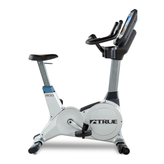
CHAPTER 3: PRODUCT OVERVIEW BIKE OVERVIEW: Quick Access Keys Console Assembly Contact Heart Rate Pads Bottle Holder Seat Adjustment Handle Pedals Coaxial Port Ethernet Port Power Cord Battery Charge Port Leveling Feet Truefitness.com / 800.426.6570 / 636.272.7100 30 of 34... -
Page 31: Chapter 3: Product Overview
CHAPTER 3: PRODUCT OVERVIEW BIKE OVERVIEW: Console Assembly: The console allows the user to set up a workout program and control the bike during a workout (For console overview and operation instructions refer to the owner’s manual for the selected console option). Quick Access Keys: Allows the user to make fast, convenient adjustments the workout intensity. - Page 32 UC900 UPRIGHT BIKE Save Time and Register Online! Activate Multiple Warranties at truefitness.com All TRUE® Fitness products are distributed by TRUE and are and warnings in owner’s manual, accident, misuse, abuse, warranted to the original registered product purchaser and the unauthorized modification, or failure to provide reasonable parts of the TRUE product (the “Product”) listed below, under...
-
Page 33: Warranty Registration
Product, this Limited Warranty will be void unless the written The UC900 upright bike comes with two serial numbers; one on authorization of TRUE is first obtained). the base and one on the display console (see diagram below). - Page 34 If you prefer to mail your warranty card, have the owner of the product complete the information below and return it to TRUE Fitness within 30 days from the date of equipment installation.
Need help?
Do you have a question about the UC900 and is the answer not in the manual?
Questions and answers