Table of Contents
Advertisement
Advertisement
Table of Contents

Related Manuals for Jungheinrich EKE 20 b


Summary of Contents for Jungheinrich EKE 20 b
- Page 1 EKE 20 b 04.02- Operating instructions 50261576 04.02...
- Page 2 Used to indicate standard equipment. Used to indicate optional equipment. Our trucks are subject to ongoing development. Jungheinrich reserves the right to alter the design, equipment and technical features of the truck. No guarantee of particular features of the truck should therefore be inferred from the present operating instructions.
-
Page 4: Table Of Contents
Table of contents Correct use and application of the truck Description of the truck Design and application ................ B 1 Assemblies ..................B 2 Technical data - standard version ............B 3 Performance data ................B 3 Dimensions ..................B 4 EN standards .................. - Page 5 Operation Safety regulations governing the operation of the fork-lift truck ..E 1 Description of the operating controls and indicators ......E 2 Starting up the truck ................E 4 Operation of the fork-lift truck .............. E 6 Safety regulations applicable when operating the truck ...... E 6 Driving, steering, braking ..............
-
Page 6: A Correct Use And Application Of The Truck
A Correct use and application of the truck The “Guidelines for the Correct Use and Application of Industrial Trucks” (VDMA) are included in the scope of delivery for this truck. The guidelines are part of these ope- rating instructions and must always be heeded. National regulations are fully applica- ble. -
Page 8: B Description Of The Truck
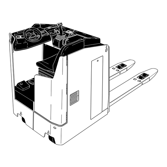
B Description of the truck Design and application The EKE 20 b is an electric pallet truck with lateral seat in four-wheel design. It is pro- vided with a driver's seat with electric steering wheel control. The EKE 20 b is designed for transport and order-picking operations on level ground. -
Page 9: Assemblies
Assemblies Item Designation Item Designation t Information and service t Battery door indicator t Control lever t Seat hood t Master switch (emerg. stop) t Drive wheel t Armrest t Supporting wheel t Battery hood t Dead man's switch t Lifting device t Parking brake t = Standard equipment o = Optional equipment... -
Page 10: Technical Data - Standard Version
Technical data - standard version Indication of technical data according to VDI 2198, subject to modification and supplementing. Performance data Designation Standard Rapid drive Q Rated capacity 2,000 2,000 Load centre distance Travelling speed 7.7 / 10.0 9.5 / 12.5 km/h with / without rated load Lifting speed... -
Page 11: Dimensions
Dimensions (all dimensions in mm) Designation Design length of front Height of fork when lowered Lift Seat height 1,020 Truck width Distance between forks, outside 510 / 540 / 670 Track 340 / 370 / 500 Distance between forks, inside 170 / 200 / 330 Fork width Safety distance... -
Page 12: En Standards
EN standards Continuous sound level: 68 dB(A) according to prEN 12053 as stipulated in ISO 4871 The continuous sound level is a value averaged according to standard regulations, taking the sound pressure level into account when driving, lifting and idling. The sound pressure level is measured at the ear. -
Page 13: Location Of Instruction Labels And Identification Labels
Location of instruction labels and identification labels 2000 1,5 V Item Designation Label “CAUTION: Low-voltage electronics” Capacity Qmax Control lever Floor load Attachment point of hooks for transportation by crane Battery identification plate Accident prevention inspection label (D only) Truck identification plate The capacity label (14) indicates the maximum capacity of the truck as Qmax. - Page 14 Truck identification plate Xxxx Xxxxxxx Xxxxxx Xxxxxxxxx Xxxxxx Xxxxxxxxx Xxxxxxxxxxxxxxxxxxx Xxxxxxxxxxxxxxxxxx Xxxxxxxxxx Xxxxxxxxxxxxxxxxx Xxxxxxxxxxxxxxxxxxx Xxxxxxxxx Xxxxxxxxxxxxxxxxxxx xxxxxxxxxx Xxxxxxxxxx Xxxxxxxxxxxxxxxxx xxxxxxxx Xxxxxxx Xxxxxx Xxxxx Xxxxxxxxxxxxxxxx Xxxx Xxxxxxxxxxxxxxxxxx Item Designation Item Designation Type Drive power Serial No. Customer no. Rated capacity in kg Min./max.
-
Page 16: C Transportation And Commissioning
C Transportation and commissioning Transportation by crane Only lifting gear of adequate capacity must be used (for the transport weight, refer to the truck identification label). Bore holes for lifting screws (1) and hoisting points at the chassis (2) can be used if hoisting gear is to be used for transporting the truck. -
Page 17: Moving The Truck With The Drive Unit Inoperative
Moving the truck with the drive unit inoperative This operating mode is not permitted when negotiating inclines and gradients. If the truck has to be moved after a failure has rendered it immobile, proceed as fol- lows: – Set the master switch to position “OFF”. –... -
Page 18: D Battery - Servicing, Recharging, Replacement
D Battery - Servicing, recharging, replace- ment Safety regulations governing the handling of lead-acid batteries The truck must be parked and rendered safe before any operations on batteries are undertaken (refer to chapter E). Servicing staff: Recharging, servicing and replacing of batteries must only be per- formed by qualified personnel. -
Page 19: Battery Types
Battery types Depending on the truck version, the truck will be supplied with different battery types. The table below shows the capacity of the batteries and also the combinations used as standard equipment. 24V - PzS - Battery 3 PzS 330L (with weights) 24V - PzS - Battery 3 PzS 420L 24V - PzS - Battery performance-enhanced 3 PzS 450HX... -
Page 20: Charging The Battery
Charging the battery To charge the battery, the truck must be parked in a closed and properly ventilated room. – Expose the battery (refer section 3). The battery connector (6) and the charging cable must only be connected or discon- nected with the truck and the battery charger switched off. -
Page 21: Removing And Installing The Battery
Removing and installing the battery The truck must be parked on level ground. To prevent short-circuits, batteries with ex- posed poles or cell connectors must be covered using a rubber mat. Place the battery connector or the battery cable, respectively, in such a way that they will not catch be- hind any truck protrusions when the battery is withdrawn. -
Page 22: Battery Discharge Indicator, Battery Discharge Monitor, Operating Hour Meter
Battery discharge indicator, battery discharge monitor, operating hour meter Battery discharge indicator: The loading status of the battery (8) is indicated in steps of 10% on the information and service indicator. The manufacturer setting of the battery discharge indicator / discharge monitor is standard batteries. -
Page 24: Safety Regulations Governing The Operation Of The Fork-Lift Truck
E Operation Safety regulations governing the operation of the fork-lift truck Driving permission: The fork-lift truck must only be operated by persons who have been trained in the operation of trucks, who have demonstrated to the user or his rep- resentative their capability of moving and handling loads, and who have expressly been charged by the user or his representative with the operation of the truck. -
Page 25: Description Of The Operating Controls And Indicators
Description of the operating controls and indicators Item Operating control or display Function t Switches the control current on and off. 1 Key switch When the key is removed from the key switch, the truck cannot be operated by un- authorised persons. - Page 26 1 2 3 4...
-
Page 27: Starting Up The Truck
Starting up the truck Before starting or operating the truck, or before lifting any loads, the driver has to make sure that nobody is within the danger area. The electronic driving and steering systems automatically control their functions. If an error or fault occurs, the driving and steering functions are stopped. - Page 28 Switching on the truck – Pull up the master switch (9). – Insert the key in the key switch (1) and turn the key clockwise towards the “I” posi- tion until reaching the stop. – Check the horn (4) for correct functioning. –...
-
Page 29: Operation Of The Fork-Lift Truck
Operation of the fork-lift truck Safety regulations applicable when operating the truck Driving lanes and work areas: Only such lanes and routes that are specially allo- cated for truck traffic must be used. Unauthorised persons must stay away from work areas. -
Page 30: Driving, Steering, Braking
Driving, steering, braking Increased attention has to be paid during driving and steering the truck. Control the steering position of the drive wheel on the information and service indica- tor (17). The electric steering system is self-monitoring. The steering control systems monitors the fault frequency over a certain period. If the same fault is detected several times during this period, the steering control reduces the driving speed of the truck to low speed. - Page 31 Driving up an incline The load must be transported facing the incline! Safety measures against “rolling down” of the truck: With the control lever (7) set to neutral, the service brake is automatically applied after a brief jolt (the controller detects the truck’s rolling down on an incline). The control lever (7) is used to release the service brake;...
- Page 32 Braking The braking behaviour of the truck strongly depends on the state of the floor. This must be taken into account by the driver for his driving behaviour. The truck may be braked in three ways: – using the service brake (break pedal (11)) –...
-
Page 33: Picking Up And Setting Down Loads
Braking by means of the generator brake (coasting) – Release the control lever (7) - control lever to neutral. Depending on the setting, the truck is braked by the generator braked, coasting to a stop. The degree of speed reduction can be set by the manufacturer service. When the service personnel has switched off the coast-down brake, only the service and/or the counter-current brake can be used. -
Page 34: Safe Parking Of The Truck
Safe parking of the truck If the truck is left unattended, even for only short periods of time, it must be rendered safe. Never park the truck on a slope or incline. The lifting device must always be complete- ly lowered. –... -
Page 35: Information And Service Indicator (Lisa)
Information and service indicator (LISA) The LCD display (19) of the LISA infor- mation and service indicator indicates the battery charge status (18), the oper- ating hours (21) and the position of the steered wheel (20). The operating data BA T T : 1 0 % 2 0 h is shown in the service and diagnosis mode (refer section 5.3). -
Page 36: Indicators
Indicators Operating data and error messages are displayed on the indicator. The operator menu can be used to set the following truck parameters: Here, the interval between maximum controller actuation ACCELERATION and 100% adjustment of the electronics is set. This driving parameter may only be adjusted by the cus- RELEASE BRAKE tom service. -
Page 37: Changing Driving Parameters
Changing driving parameters The driving behaviour of the truck is changed if the truck parameters are modified. This is to be taken into consideration during start-up! Parameters may only be modified with the truck parked and while it is not performing any lifting movements. -
Page 38: Fault Location
Fault location This chapter enables the operator to locate and rectify minor faults and malfunctions, or the effects of operating errors. When trying to locate a fault, proceed in the order shown in the table. Fault Possible cause Remedial action Truck does –... - Page 39 E 16...
-
Page 40: F Maintenance Of The Fork Lift Truck
F Maintenance of the fork lift truck Operational safety and environmental protection The checks and servicing operations contained in this chapter must be performed in accordance with the intervals as indicated in the servicing checklists. Modifications of fork lift truck assemblies, especially of the safety installations, are not permitted. - Page 41 Work on the electric system: Work on the electric system of the truck must only be performed by personnel specially trained for such operations. Before commencing any work on the electric system, all measures required to prevent electric shocks have to be taken. For battery-operated fork lift trucks, the truck must also be depow- ered by removing the battery plug.
-
Page 42: Servicing And Inspection
Servicing and inspection Thorough and expert servicing is one of the most important preconditions for safe op- eration of the fork-lift truck. The neglect of regular servicing intervals can lead to fork- lift truck failure and constitutes a potential hazard to personnel and equipment. The indicated servicing intervals are based on single-shift operation under normal op- erating conditions. -
Page 43: Maintenance Checklist
Maintenance checklist Maintenance intervals t W M M M Standard = Cold-storage depot = k 1 3 6 12 Chassis/ 1.1 Check all load bearing elements for damage Design: 1.2 Check all bolted connections 1.3 Check platform for correct functioning and damage Drive unit: 2.1 Check the transmission for noises and leakage 2.2 Check the transmission oil level... - Page 44 Maintenance intervals t W M M M Standard = Cold-storage depot = k 1 3 6 12 Electrical sys- 9.1 Performance check tem: 9.2 Check all cables for secure connection and damage 9.3 Check the fuses for correct amperage 9.4 Check switches and trip cams for secure attachment and correct functioning 9.5 Check the warning installations and safety circuits for correct functioning...
-
Page 45: Lubrication Schedule
Lubrication schedule 0,7 l A + C 1,25 - 1,3 l B + C Gliding surfaces Grease nipples Filler plug for hydraulic oil Filler plug for gear oil Drain plug for gear oil Cold store usage Compound for cold store usage 1:1 1.25l - 1.3l;... -
Page 46: Fuels, Coolants And Lubricants
Fuels, coolants and lubricants Handling consumption type material: Consumption type material must always be handled properly. Manufacturer's instructions are to be observed. Improper handling is injurious to health, life, and environment. Consumption type ma- terials must be stored in adequate containers. They might be inflammable and, there- fore, must not come into contact with hot components or open fire. -
Page 47: Instructions For The Servicing Operations
Instructions for the servicing operations Preparing the truck for servicing and maintenance operations All required safety measures must be taken to prevent any accidents in the course of the servicing and maintenance operations. The following preparatory operations must be performed: –... -
Page 48: Opening The Battery Hood
Opening the battery hood – Use the service key to unlock the battery hood (3). – Swing the battery hood (4) upward and lock it. Opening the seat hood – Use the hex key located beneath the armrest (2) to open the seat hood (5). –... -
Page 49: Opening The Control Flap
Opening the control flap – Open the latch (9) with the hex key (located beneath the armrest (2)). – Take out the control flap (10) and put it aside. The drive current control system and the truck fuses are readily accessible for serv- icing purposes. -
Page 50: Tightening The Wheel Screws
Tightening the wheel screws The wheel screws of the drive wheel must be retightened in accordance with the serv- icing intervals indicated in the servicing checklist. – Position the drive wheel (12) at right angles to the longitudinal axis of the truck. –... -
Page 51: Checking The Electric Fuses
Checking the electric fuses – Prepare the truck for the servicing and maintenance operations (refer to chapter F, section 6.1). – Open the hoods (refer to chapter F, section 6.3 and 6.4). – Referring to the table, check all fuses for correct rating and damage; replace fuses where required. -
Page 52: Recommissioning The Truck
Recommissioning the truck Recommissioning of the truck following the performance of cleaning or maintenance work is permitted only after the following operations have been performed: – Check the horn for proper functioning. – Check the master switch for correct functioning. –... -
Page 53: Recommissioning The Truck
Recommissioning the truck – Thoroughly clean the fork lift truck. – Lubricate the fork lift truck according to the lubrication chart (refer to chapter F). – Clean the battery. Grease the pole screws using pole grease and reconnect the battery. –...
Need help?
Do you have a question about the EKE 20 b and is the answer not in the manual?
Questions and answers