
Related Manuals for Samson 3331/BR 31a


Summary of Contents for Samson 3331/BR 31a
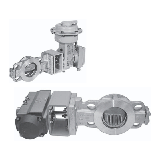
- Page 1 Pneumatic Control Valve Type 3331/BR 31a Special version Type 3331/3278 Type 3331 Butterfly Valve Fig. 1 · Type 3331/BR 31a (below) and Type 3331/3278 (top) Mounting and Operating Instructions EB 8227 EN Edition July 2004...
-
Page 2: Table Of Contents
Contents Contents Page Design and principle of operation ....4 Installation ....... 6 Assembling butterfly valve and rotary actuator . - Page 3 The corresponding declaration of conformity can be viewed and down- loaded on the Internet at http://www.samson.de. For appropriate operation, make sure that the control valve is only used in areas where the operating pressure and temperatures do not exceed the op- erating values which are based on the valve sizing data submitted in the or- der.
-
Page 4: Design And Principle Of Operation
The fail-safe position of the control valve upon failure of the supply air is determined The pneumatic control valve consists of a by the version of Type 3331/BR 31a (sin- Type 3310 Butterfly Valve and either a gle-acting Type SRP) or depending on how... - Page 5 Design and principle of operation Pfeiffer Type BR 31a Actuator Type 3278 Actuator Swing-through Angle-seated/ disc low-noise disc Valve body Internal bearing Gland flange Plug Yoke Type BR 31a Actuator Shaft 12.1 Stop 4.2 Feather key 12.2 Stop screw Packing Type 3278 Actuator Spring 13.1 Stop screw...
-
Page 6: Installation
Installation Installation Valve CLOSED without supply air 1. Place disc (8) in closed position (0° an- Assembling butterfly valve gle of rotation). and rotary actuator 2. Fasten yoke (3) with 2 or 4 screws de- pending on the nominal size of the valve Note! to the flange of the shaft (4). -
Page 7: Type 3331/3278
Installation Valve CLOSED without supply air 4. Turn the stop screw (12.1 or 12.2, de- pending on the direction of rotation) un- 1. Undo both stop screws (13.1 and 13.2) til the valve is completely open at 90°. at the actuator. Rescrew stop screw Align the markings on the shaft with the (13.2) to the point where the grooves of markings on the gland flange. -
Page 8: Mounting Position
(e.g. Type 3776/ 3777). The butterfly valve may be installed vertically In conjunction with SAMSON positioners, or horizontally in the pipeline. However, the suitable accessories are available for connec- following points must be observed for the di- tion. -
Page 9: Operation
Operation Operation Maintenance Changing the fail-safe Note! position Before performing any maintenance work on the control valve, The fail-safe position of the Type 3278 depressurize the concerned section Actuator can be changed from “Valve of the plant and drain the process CLOSED without supply air”... -
Page 10: Customer Inquiries
Customer inquiries Customer inquiries Please submit the following details: Order number Type designation, model number, nomi- nal size and version of the valve Pressure and temperature of the process medium Flow rate in m Bench range (spring range) of the actua- Installation drawing Dimensions and weights Refer to the Data Sheet T 8227 EN for the... - Page 11 EB 8227 EN...
- Page 12 SAMSON AG ⋅ MESS- UND REGELTECHNIK Weismüllerstraße 3 ⋅ 60314 Frankfurt am Main ⋅ Germany Phone +49 69 4009-0 ⋅ Fax +49 69 4009-1507 EB 8227 EN Internet: http://www.samson.de...
Need help?
Do you have a question about the 3331/BR 31a and is the answer not in the manual?
Questions and answers