Table of Contents
Advertisement
Features
•
Compatible with MCS-51
•
8 Kbytes of In-System Reprogrammable Flash Memory
Endurance: 1,000 Write/Erase Cycles
•
Fully Static Operation: 0 Hz to 24 MHz
•
Three-Level Program Memory Lock
•
256 x 8-Bit Internal RAM
•
32 Programmable I/O Lines
•
Three 16-Bit Timer/Counters
•
Eight Interrupt Sources
•
Programmable Serial Channel
•
Low Power Idle and Power Down Modes
Description
The AT89C52 is a low-power, high-performance CMOS 8-bit microcomputer with 8
Kbytes of Flash programmable and erasable read only memory (PEROM). The de-
vice is manufactured using Atmel's high density nonvolatile memory technology and
is compatible with the industry standard 80C51 and 80C52 instruction set and pinout.
The on-chip Flash allows the program memory to be reprogrammed in-system or by
a conventional nonvolatile memory programmer. By combining a versatile 8-bit CPU
with Flash on a monolithic chip, the Atmel AT89C52 is a powerful microcomputer
which provides a highly flexible and cost effective solution to many embedded control
applications.
Pin Configurations
PQFP/TQFP
I N D E X
C O R N E R
4 4
4 2
4 0
4 3
4 1
3 9
( M O S I ) P 1 . 5
1
( M I S O ) P 1 . 6
2
( S C K ) P 1 . 7
3
R S T
4
( R X D ) P 3 . 0
5
N C
6
( T X D ) P 3 . 1
7
( I N T 0 ) P 3 . 2
8
9
( I N T 1 ) P 3 . 3
( T 0 ) P 3 . 4
1 0
( T 1 ) P 3 . 5
1 1
1 3
1 5
1 7
1 6
1 2
1 4
TM
Products
3 6
3 4
3 5
P 0 . 4 ( A D 4 )
3 3
P 0 . 5 ( A D 5 )
3 2
P 0 . 6 ( A D 6 )
3 1
P 0 . 7 ( A D 7 )
3 0
2 9
E A / V P P
2 8
N C
2 7
A L E / P R O G
P S E N
2 6
2 5
P 2 . 7 ( A 1 5 )
2 4
P 2 . 6 ( A 1 4 )
2 3
P 2 . 5 ( A 1 3 )
1 9
2 1
1 8
2 0
2 2
( M O S I ) P 1 . 5
( M I S O ) P 1 . 6
( S C K ) P 1 . 7
( R X D ) P 3 . 0
( T X D ) P 3 . 1
( I N T 0 ) P 3 . 2
( I N T 1 ) P 3 . 3
(continued)
PDIP/Cerdip
( T 2 ) P 1 . 0
4 0
V C C
1
( T 2 E X ) P 1 . 1
2
3 9
P 0 . 0 ( A D 0 )
P 1 . 2
3
3 8
P 0 . 1 ( A D 1 )
3 7
P 1 . 3
4
P 0 . 2 ( A D 2 )
( S S ) P 1 . 4
5
3 6
P 0 . 3 ( A D 3 )
( M O S I ) P 1 . 5
6
3 5
P 0 . 4 ( A D 4 )
7
3 4
( M I S O ) P 1 . 6
P 0 . 5 ( A D 5 )
3 3
P 0 . 6 ( A D 6 )
( S C K ) P 1 . 7
8
R S T
3 2
P 0 . 7 ( A D 7 )
9
( R X D ) P 3 . 0
1 0
3 1
E A / V P P
( T X D ) P 3 . 1
1 1
3 0
A L E / P R O G
P S E N
( I N T 0 ) P 3 . 2
1 2
2 9
2 8
P 2 . 7 ( A 1 5 )
( I N T 1 ) P 3 . 3
1 3
( T 0 ) P 3 . 4
2 7
P 2 . 6 ( A 1 4 )
1 4
( T 1 ) P 3 . 5
1 5
2 6
P 2 . 5 ( A 1 3 )
( W R ) P 3 . 6
1 6
2 5
P 2 . 4 ( A 1 2 )
( R D ) P 3 . 7
1 7
2 4
P 2 . 3 ( A 1 1 )
X TA L 2
2 3
1 8
X TA L 1
1 9
2 2
G N D
2 0
2 1
P 2 . 0 ( A 8 )
PLCC/LCC
I N D E X
C O R N E R
6
4
2
4 4
4 2
4 0
5
3
1
4 3
4 1
7
8
9
R S T
1 0
1 1
N C
1 2
1 3
1 4
1 5
1 6
( T 0 ) P 3 . 4
1 7
( T 1 ) P 3 . 5
1 9
2 1
2 3
2 5
2 7
2 8
1 8
2 0
2 2
2 4
2 6
8-Bit
Microcontroller
with 8 Kbytes
Flash
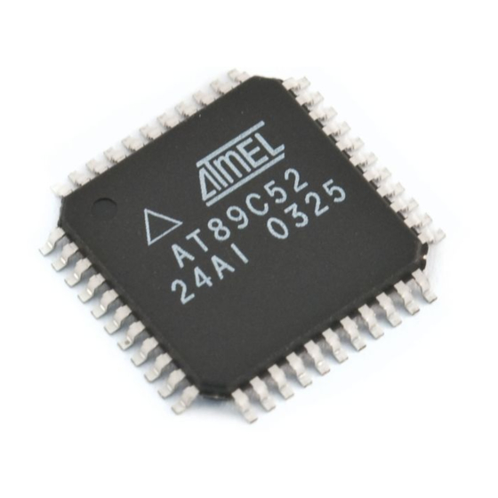
AT89C52
P 2 . 2 ( A 1 0 )
P 2 . 1 ( A 9 )
3 9
P 0 . 4 ( A D 4 )
P 0 . 5 ( A D 5 )
P 0 . 6 ( A D 6 )
3 6
P 0 . 7 ( A D 7 )
3 5
E A / V P P
3 4
N C
3 3
A L E / P R O G
3 2
P S E N
3 1
P 2 . 7 ( A 1 5 )
3 0
P 2 . 6 ( A 1 4 )
2 9
P 2 . 5 ( A 1 3 )
0313E
Advertisement
Table of Contents

Subscribe to Our Youtube Channel
Related Manuals for Atmel AT89C52


Summary of Contents for Atmel AT89C52
- Page 1 The on-chip Flash allows the program memory to be reprogrammed in-system or by a conventional nonvolatile memory programmer. By combining a versatile 8-bit CPU AT89C52 with Flash on a monolithic chip, the Atmel AT89C52 is a powerful microcomputer which provides a highly flexible and cost effective solution to many embedded control applications.
-
Page 2: Block Diagram
TMP2 TMP1 INCREMENTER INTERRUPT, SERIAL PORT, AND TIMER BLOCKS PROGRAM COUNTER PSEN TIMING ALE/PROG INSTRUCTION DPTR REGISTER CONTROL EA / V PORT 1 PORT 3 LATCH LATCH PORT 1 DRIVERS PORT 3 DRIVERS P1.0 - P1.7 P3.0 - P3.7 AT89C52... -
Page 3: Pin Description
The Port 2 output buffers can sink/source four TTL inputs. circuitry. In addition, the AT89C52 is designed with static When 1s are written to Port 2 pins, they are pulled high by logic for operation down to zero frequency and supports the internal pullups and can be used as inputs. - Page 4 Input to the inverting oscillator amplifier and input to the gram memory. internal clock operating circuit. When the AT89C52 is executing code from external pro- XTAL2 gram memory, PSEN is activated twice each machine cy- Output from the inverting oscillator amplifier.
-
Page 5: Special Function Registers
Data Memory For example, the following direct addressing instruction accesses the SFR at location 0A0H (which is P2). The AT89C52 implements 256 bytes of on-chip RAM. The MOV 0A0H, #data upper 128 bytes occupy a parallel address space to the Instructions that use indirect addressing access the upper Special Function Registers. - Page 6 The new count value appears in the Timer 0 and Timer 1 in the AT89C52 operate the same register during S3P1 of the cycle following the one in way as Timer 0 and Timer 1 in the AT89C51.
- Page 7 AT89C52 Auto-Reload (Up or Down Counter) (Continued) overflow also causes the timer registers to be reloaded RCAP2H and RCAP2L to be reloaded into the timer regis- with the 16-bit value in RCAP2H and RCAP2L. The values ters, TH2 and TL2, respectively.
- Page 8 NOTE: OSC. FREQ. IS DIVIDED BY 2, NOT 12 SMOD1 ÷ C/T2 = 0 "1" "0" RCLK CLOCK CONTROL ÷ C/T2 = 1 "1" "0" T2 PIN TCLK RCAP2H RCAP2L CLOCK TRANSITION ÷ DETECTOR TIMER 2 T2EX PIN EXF2 INTERRUPT CONTROL EXEN2 AT89C52...
- Page 9 AT89C52 however, it increments every state time (at 1/2 the oscilla- Baud Rate Generator tor frequency). The baud rate formula is given below. Timer 2 is selected as the baud rate generator by setting Modes 1 and 3 Oscillator Frequency TCLK and/or RCLK in T2CON (Table 2).
- Page 10 External interrupt 0 enable bit. UART User software should never write 1s to unimplemented bits, because they may be used in future AT89 products. The UART in the AT89C52 operates the same way as the UART in the AT89C51. Figure 6. Interrupt Sources Interrupts...
-
Page 11: Oscillator Characteristics
AT89C52 Oscillator Characteristics Figure 7. Oscillator Connections XTAL1 and XTAL2 are the input and output, respectively, of an inverting amplifier that can be configured for use as XTAL2 an on-chip oscillator, as shown in Figure 7. Either a quartz crystal or ceramic resonator may be used. To drive the... - Page 12 Program Memory Lock Bits The AT89C52 has three lock bits that can be left unpro- powered up without a reset, the latch initializes to a ran- grammed (U) or can be programmed (P) to obtain the ad- dom value and holds that value until reset is activated. The ditional features listed in the following table.
-
Page 13: Programming Interface
All major programming vendors offer worldwide support ten with all 1s. The chip erase operation must be executed for the Atmel microcontroller series. Please contact your before the code memory can be reprogrammed. local programming vendor for the appropriate software re- Reading the Signature Bytes: The signature bytes are vision. - Page 14 Figure 10. Verifying the Flash Memory Figure 9. Programming the Flash Memory AT89C52 AT89C52 A0 - A7 A0 - A7 ADDR. ADDR. OOOOH/1FFFH PGM DATA OOOOH/1FFFH P2.0 - P2.4 P2.0 - P2.4 (USE 10K DATA A8 - A12 A8 - A12 PULLUPS) P2.6...
- Page 15 AT89C52 Flash Programming and Verification Waveforms - High Voltage Mode PROGRAMMING VERIFICATION P1.0 - P1.7 ADDRESS ADDRESS P2.0 - P2.4 P3.0 AVQV PORT 0 DATA IN DATA OUT DVGL GHDX AVGL GHAX ALE/PROG SHGL GHSL GLGH LOGIC 1 EA/V LOGIC 0...
-
Page 16: Absolute Maximum Ratings
Pins are not guaranteed to sink Maximum I per 8-bit port: current greater than the listed test conditions. Port 0:26 mA 2. Minimum V for Power Down is 2 V. Ports 1,2, 3:15 mA AT89C52... - Page 17 AT89C52 A.C. Characteristics Under operating conditions, load capacitance for Port 0, ALE/PROG, and PSEN = 100 pF; load capacitance for all other outputs = 80 pF. External Program and Data Memory Characteristics 12 MHz Oscillator Variable Oscillator Symbol Parameter Units...
- Page 18 AVLL RLAZ RHDX A0 - A7 FROM RI OR DPL DATA IN A0 - A7 FROM PCL INSTR IN PORT 0 AVWL AVDV PORT 2 P2.0 - P2.7 OR A8 - A15 FROM DPH A8 - A15 FROM PCH AT89C52...
-
Page 19: External Clock Drive Waveforms
AT89C52 External Data Memory Cycle LHLL WHLH PSEN LLWL WLWH LLAX QVWX WHQX AVLL QVWH PORT 0 A0 - A7 FROM RI OR DPL DATA OUT A0 - A7 FROM PCL INSTR IN AVWL PORT 2 P2.0 - P2.7 OR A8 - A15 FROM DPH... - Page 20 100-mV change from load voltage occurs. A urements are made at V min. for a logic 1 and port pin begins to float when a 100-mV change from max. for a logic 0. the loaded V level occurs. AT89C52...
-
Page 21: Ordering Information
AT89C52 Ordering Information Speed Power Ordering Code Package Operation Range (MHz) Supply 5 V ± 20% AT89C52-12AC Commercial AT89C52-12JC (0°C to 70°C) AT89C52-12PC 40P6 AT89C52-12QC AT89C52-12AI Industrial AT89C52-12JI (-40°C to 85°C) AT89C52-12PI 40P6 AT89C52-12QI AT89C52-12AA Automotive AT89C52-12JA (-40°C to 125°C) - Page 22 Ordering Information Speed Power Ordering Code Package Operation Range (MHz) Supply 5 V ± 20% AT89C52-24AC Commercial AT89C52-24JC (0°C to 70°C) AT89C52-24PC 44P6 AT89C52-24QC AT89C52-24AI Industrial AT89C52-24JI (-40°C to 85°C) AT89C52-24PI 44P6 AT89C52-24QI Package Type 44 Lead, Thin Plastic Gull Wing Quad Flatpack (TQFP) 40D6 40 Lead, 0.600"...
Need help?
Do you have a question about the AT89C52 and is the answer not in the manual?
Questions and answers