Table of Contents
Advertisement
Advertisement
Table of Contents

Subscribe to Our Youtube Channel
Related Manuals for CAS EB Series


Summary of Contents for CAS EB Series
- Page 1 Service Manual EB SERVICE MANUAL 2007/06/13...
-
Page 2: Table Of Contents
Service Manual < Table of Contents > Introduction ..........................4 1.1. Preface ............................ 4 1.2. Precaution ..........................4 1.3. Specifications ........................5 1.4. Dimension..........................6 1.5. Key & SYMBOLS ON DISPLAY ..................7 1.6. Sealing Method........................9 Calibration ..........................11 2.1. - Page 3 Service Manual 6.4. Rear Display PCB (Bottom)..................26 6.5. Terminal PCB (Top) ....................... 27 6.6. Terminal PCB (Bottom) ....................27 6.7. Cal PCB (Top) ........................28 Error Messages & Solution....................29 Part List............................30 2007/06/13...
-
Page 4: Introduction
WE hope that your departments enjoy with high quality of CAS product. This manual will help you with proper operations and care of the EB series. Please keep it handy for the future references. 1.2. Precaution •... -
Page 5: Specifications
Service Manual 1.3. Specifications EB -60 EB-150 60 kg / 0.02 kg 150 kg / 0.5 kg Capacity / e 1 / 60,000 1 / 60,000 Internal 1/3,000 (Dual) 1/3,000 (Dual) External 29.99 Kg 59.98 Kg Tare Display Weight(6), unit price(6), total price(6) Indicators STABLE, ZERO, NET, Battery Number(0~9, 00), Clear, ZERO, TARE, PLU Save, PLU Call,... -
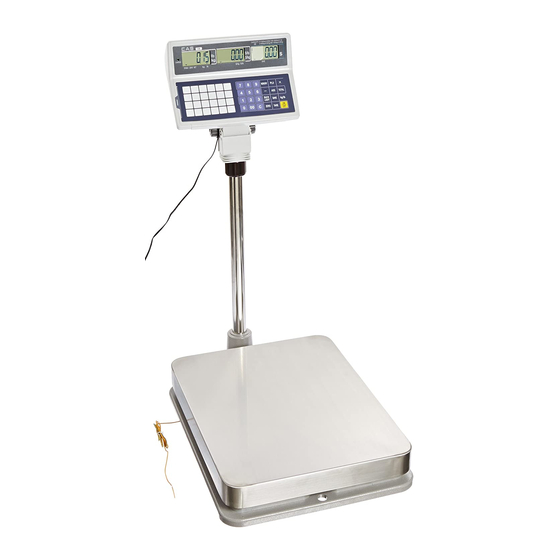
Page 6: Dimension
Service Manual 1.4. Dimension 2007/06/13... -
Page 7: Key & Symbols On Display
Service Manual 1.5. Key & SYMBOLS ON DISPLAY SYMBOLS DESCRIPTION To adjust zero Stable status Tare on Charge status Display battery status Back Light On status KEYS FUNCTIONS To input all of numerical data Direct PLU keys (24EA) To save PLU To call up PLU 2007/06/13... - Page 8 Service Manual To clear data To set zero To set or clear tare value To turn on & off the scale To turn on & off the backlight Display battery voltage(%) To make several sales transaction by adding up To make discount transaction To multiply the same item when making sales transaction To check total sales amount or finalize sales transaction To soft key...
-
Page 9: Sealing Method
Service Manual 1.6. Sealing Method [PLATE] 2007/06/13... - Page 10 Service Manual [STICKER] 2007/06/13...
-
Page 11: Calibration
Service Manual 2. Calibration 2.1. General Calibration Pressing and holding calibration switch press [POWER] key to go to calibration mode. User can move to other mode by using [ZERO] key in the calibration mode. User also moves to other sub-modes for each mode by using [TARE] key. Please simply follow below procedure to move to other mode. -
Page 12: C4 Setting
Service Manual < Modes > 2.1.1. C4 Setting 2.1.1.1. C4-1 Setting BIT 6~7 Initial Zero range Proper tare BIT5 Tare Type Full Tare BIT4 (+), (-) Direction successive Tare (-) Direction successive Tare Successive tare BIT 2~3 (+) Direction successive Tare One Time tare BIT1 BIT0... -
Page 13: C4-4 Setting
Service Manual Don't use BIT5 Use Back light Don't use BIT4 Use Head message Don't clear BIT3 Use gram Clear Don't clear BIT2 Use oz Clear Don't use BIT1 Use lb BIT0 Use Kg 2.1.1.4. C4-4 Setting BIT7 BIT6 00, 25, 50, 75 00, 10, 20 BIT 4~5 Price round off... -
Page 14: Span Calibration Setting (C-3)
Service Manual O.OOOO O.OOO O.OO Don't use BIT3 Use Unit message BIT2 Don't use DEP-50 BIT 0~1 Print type 2.1.2. SPAN Calibration Setting (C-3) (1) Pressing and holding “Calibration Switch” press [POWER] key. After “CAL” message blinks three times and shows the version of scale, it displays “CAL 1” message. -
Page 15: Calibration Factor Setting (C-10)
Service Manual (3) Press [TARE] key, and then “ G-1“ message and “9.7994” will be shown. The first digit,”9” will blink. (4) Input a gravitational acceleration value by using [ZERO] key. (5) Press [TARE] key, and then “G-2“ message blinks.“9.7994” will be shown. The first digit,”9”... -
Page 16: Input Function Key Code (C-6)
Service Manual 2.1.6. Input Function Key Code (C-6) (1) Under the calibration switch ON press [POWER] key. “CAL” message blinks three times. (2) Press [ZERO] to display “C-6”. (3) “E-SET” display on the weight window. (4) “XX” message shows up on the total price window. (5) Input “Soft Key Code”... -
Page 17: Percent Calibration (C-7)
Service Manual KG/LB TEST HOLD PRINT NO FUNCTION EURO PERSENT TARE TARE SAVE BOTH SAVE PERSET MUL ”X” 32~59 2.1.7. Percent Calibration (C-7) (1) Pressing and holding “Calibration Switch” press [POWER] key. After “CAL” message blinks three times and shows the version of scale, it displays “CAL 1” message. -
Page 18: The Schematics And Diagram
Service Manual 3. The Schematics and Diagram 3.1. System Block Diagram MAIN RS232 BOARD (BCO) REAR ONE MODULE DISPLAY RECHARGE LCD Display Driver POWER Pb BATTERY (12V Adaptor) (6V 5Ah) 2007/06/13... -
Page 19: Circuit Diagram
Service Manual 3.2. Circuit Diagram 3.2.1. Main and Power CN3 Power_SW U3 LM7809 1 2 3 D9 SS14 U1 MC34063A A_Vcc XC6204C502MR L13 220uH 0.33 2W SS14 VOUT 1N5406 SS14 TCAP 0.1uF 470uF/35V 100u/16v 0.1uF SS14 Adaptor 470pF COMP 470uF/35V 전원사양(+5V , Bat) 470uF/35V... -
Page 20: Display Part
Service Manual 3.2.2. Display part SEG0 SEG1 SEG2 SEG3 SEG4 SEG5 COM0 COM0 COM1 COM1 COM2 COM2 COM3 COM3 COM4 COM4 COM5 COM5 COM6 COM6 COM7 COM7 SEG6 SEG7 SEG8 Weight_DISPLAY LCD CS SEG18 LCD RD SEG19 SEG19 LCD WR SEG19 SEG18 SEG20... -
Page 21: Key Part
Service Manual 3.2.3. Key Part PLU1 PLU2 PLU3 PLU4 PLU5 PLU6 ZERO1 TARE1 MDOE1 PLU7 PLU8 PLU9 PLU10 PLU11 PLU12 PAD1 ADD1 PLU13 PLU14 PLU15 PLU16 PLU17 PLU18 PAY 1 TTL1 PLU19 PLU20 PLU21 PLU22 PLU23 PLU24 CLEAR1 CAN1 TTL2 CON8 CON8 0.1u... -
Page 22: Exploded View
Service Manual 4. Exploded View 2007/06/13... -
Page 23: Load Cell Drawing
Service Manual 5. Load Cell drawing 2007/06/13... -
Page 24: Part Location
Service Manual 6. Part Location 6.1. Main PCB (Top) 2007/06/13... -
Page 25: Main Pcb (Bottom)
Service Manual 6.2. Main PCB (Bottom) 2007/06/13... -
Page 26: Rear Display Pcb (Top)
Service Manual 6.3. Rear Display PCB (Top) 6.4. Rear Display PCB (Bottom) 2007/06/13... -
Page 27: Terminal Pcb (Top)
Service Manual 6.5. Terminal PCB (Top) 6.6. Terminal PCB (Bottom) 2007/06/13... -
Page 28: Cal Pcb (Top)
Service Manual 6.7. Cal PCB (Top) 2007/06/13... -
Page 29: Error Messages & Solution
Service Manual 7. Error Messages & Solution Error Message Description Solution on Display Please call your CAS The "Err 1" occurs when a current zero point has "Err 1" dealer. shifted from the last span calibration. Please call your CAS The "Err 2"... -
Page 30: Part List
Service Manual 8. Part List CODE NAME SPEC Q'TY 1 7002Z0000000 PIEZO BUZZER APR,ADR(CHINA) 2 7802CLL00030 CONNECTOR(WAFER) LWL0640-03 (LSW250-03) 3 7805CCN67030 CONNECTOR(WAFER) 03-5267 4 7801CLW00050 CONNECTOR(WAFER) LW0640-05(GOLD) (LPH01-05A) 5 7805CCN67020 CONNECTOR(WAFER) 02-5267 6 7804CCN73030 CONNECTOR(WAFER) 5273-03 (LPH03-03) CONDENSER-ELECTRIC 470uF/35V(short type) 8 6712CHP01040 CONDENSER-CHIP CL21F 104KBNC... - Page 31 Service Manual 21 6281I0022220 TRANSISTOR CHIP 2N2222AS 22 6281I0015040 TRANSISTOR CHIP KTA1504 SY 23 6527ID301000 RESISTOR-CHIP 1/10W RR1220P-103D(10K) 24 6598IJ301000 RESISTOR-CHIP-ARRAY RP164P103J(=1608 10kΩ X 4PCS) RESISTOR 2W 0.33 2W 26 6527ID300200 RESISTOR-CHIP 1/10W RR1220P-202D(2 ㏀) 27 6527ID300220 RESISTOR-CHIP 1/10W RR1220P-222D(2.2K) 28 6527ID300100 RESISTOR-CHIP 1/10W RR1220P-102D(1K)
Need help?
Do you have a question about the EB Series and is the answer not in the manual?
Questions and answers