Table of Contents
Advertisement
Advertisement
Chapters
Table of Contents

Subscribe to Our Youtube Channel
Related Manuals for Optex THERMO-HUNTER BUILT-IN


Summary of Contents for Optex THERMO-HUNTER BUILT-IN
- Page 1 Non-Contact Thermometer Instruction Manual THERMO-HUNTER BUILT-IN CS-30TAC , CS-40TAC CS-30TAC-HT , CS-40TAC-HT OPTEX FA CO., LTD. 91 Chudoji-Awata-cho Shimogyo-ku Kyoto 600-8815 JAPAN TEL: +81-75-325-1314 FAX: +81-75-325-2936 Printed in JAPAN 1941-4 2013/09...
-
Page 2: Table Of Contents
○ After reading this manual, please retain it for future reference. ○ OPTEX is not liable for any incidental or consequential damages or losses including losses of data or changes of measurement, arising from accident, misuse or abnormal conditions of operation or handling. -
Page 3: Safe Usage
Safe Usage This instruction manual contains various warnings for your safety and proper usage to avoid possible personal injury. Please be sure to heed the warnings and strictly follow safety instructions. This symbol signifies that improper usage may result in injuries or Caution damage. -
Page 4: Specifi Cations
Specifi cations Model CS-30TAC-HT CS-40TAC-HT CS-30TAC CS-40TAC Temperature range 0 °C to 1000 °C -40 °C to 500 °C φ 30/500 mm φ 40/500 mm φ 30/500 mm φ 40/500 mm Area size 22:1 15:1 22:1 15:1 Optics Silicon lens(Water-repellent coat, Oil-repellent coat) Detection element / Thermopile/ 8 to 14 μm Wavelength... -
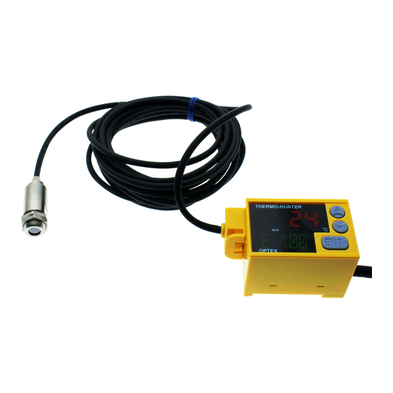
Page 5: External Dimensions/Parts Name
External Dimensions/Parts Name Lens surface Sensor head [mm] φ 7 Sensor cable φ 4×3000 (MAX) Cable No. Amplifi er DIN rail attachment part Output cable Cable cover φ 6×2000 (MAX) Serial No. Cable No. Main display ▲ / ▼ buttons ENT. -
Page 6: Wiring Diagram
Wiring Diagram Output cable . . . 15 pieces Dot mark 1 Dot mark 2 Output cable Descriptions Dot mark Line color Color Quantity Pink 12 to 24 VDC Power supply Gray Black White + Analog output 4-20 mA White Black -... - Page 7 Sensor cable When you cut the sensor cables, ensure to perform [mm] end treatment and connection of the cables. (1) Cut the cables to a desired length and treat their end as shown in the left fi gure. A guide wire is sheathed in the shielded mesh cable.
-
Page 8: Mounting/Installation
Mounting/Installation Sensor head The external screw is M12 × P1.0. Fix securely into the hole of φ12 mm or more using the attached hexagon nut. The optional mounting fi tting can help you adjust the angle easily. ○ Mounting Mount the sensor head perpendicular to the target. -
Page 9: Field Of View
Field of View [CS-30TAC/CS-30TAC-HT] φ 7/0 φ 12/100 φ 21/300 φ 30/500 D (distance) : S (area) = 22:1 [CS-40TAC/CS-40TAC-HT] φ 7/0 φ 14/100 φ 27/300 φ 40/500 Area size/Distance D:S = 15:1 [mm] [For correct measurement] The range of fi eld of view is equivalent to 90% of optical response (energy). The target measured should be suffi... -
Page 10: How To Use
How to Use (1) Check that the connections are correct and turn the power 8. 8 . 8 . 8 The display fl ashes and temperature measurement starts. 8. 8 . 8 . 8 (2) Check that the unit performs normal operation. Put your hand over the head part to check that the measurement value changes. -
Page 11: Function List
Function List To change the settings, press the ENTER button for three seconds or more. The settable items are shown below. Change the settings as necessary. While the indication fl ashes, the settings are being read or written and the button operation is not accepted. -
Page 12: Setup Of Functions
Setup of Functions BANK ● : BANK/ Bank mode Select the bank No. to make the setting. BANK There are four banks (1 to 4) in total, each of which can have its own setting. The No. displayed fi rst is that of the bank enabled in normal operation. - Page 13 TECH ○ : TECH/ Teach mode TECH E1. 0 0 E0. 9 0 (1) Press the ENTER button in the Teach mode after confi rming the target is aimed suffi ciently larger than the fi eld of view. (2) When the current measurement value is displayed, input the temperature of the target.
- Page 14 Setup of Functions AADJ ○ : AADJ/ Analog Adjust mode This setting is for adjusting the measurement value with the specifi ed value AADJ according to the measuring targets. A intended value can be output by setting L (lower limit value) and H (upper limit value) conforming to the both specifi ed value.
-
Page 15: Ascl Mode
* The minimum temperature width for upper limit value and lower limit value is 10 degree. Temperature Temperature After adjustment Energy Energy ASCL ● : ASCL/ Analog Scale mode You can change the temperature range of analog ASCL ASCL output (4 - 20 mA) within the measurement temperature range. -
Page 16: Alam Mode
Setup of Functions ALAM ● : ALAM/ Alarm (contact) output mode You can set the temperature and output method of ALAM ALAM alarm (contact)output. H (upper limit value): Output turns on when the value exceeds the Setting value. L (lower limit value): Output turns on when the value falls below the Setting value. - Page 17 (1) Switch from OFF to ON and press the ENTER button to confi rm the setting. (2) When the upper limit value is displayed, press the ▲/▼ buttons to input the temperature. (3) Press the ENTER button to confi rm the setting. * To cancel the setting, select OFF and press the ENTER button.
-
Page 18: Trig Mode
Setup of Functions TRIG ● : TRIG/ Trigger (synchronous) input mode You can select the output control at the time of trigger (synchronous) input. TRIG NONE: No setting EXT: External trigger input WAVE: WAVE trigger input * Output is controlled by setting the specifi ed temperature as the judgment criterion value (WAVE LIMIT). - Page 19 ○ : EXT/ External Trigger mode (1) In the TRIG mode, select EXT and press the ENTER button to confi rm the TRIG setting. (2) Select the analog output at the time of trigger input. (3) Press the ENTER button to confi rm the setting. HOLD HOLD HOLD...
-
Page 20: Eco Mode
Setup of Functions ● Combination of alarm output and trigger input This unit allows individual setting for each function. The behavior when the alarm output and trigger input are combined is as described below. The alarm output uses the analog output value as the judgment criterion, so when the trigger input is set, the controlled analog output will be the judgment criterion. -
Page 21: End Mode
● : END mode You can save (SET) or cancel (CSEL) the setting and change the bank No. to make the setting. * The Setting values become valid only after they are saved. The setting is restored to its previous state if the unit returns to the measurement mode without saving them or the Setting values are canceled. -
Page 22: Troubleshooting
Troubleshooting Problem Cause Action The power is not applied. Check the cabling and connections. Cannot measure. Check the power voltage and adjust it to The power voltage is low. the 12 to 24 VDC range. Clean the lens referring to the Lens section The lens is dirty.
Need help?
Do you have a question about the THERMO-HUNTER BUILT-IN and is the answer not in the manual?
Questions and answers