Sign In
Upload
Download
Table of Contents
Contents
Add to my manuals
Delete from my manuals
Share
URL of this page:
HTML Link:
Bookmark this page
Add
Manual will be automatically added to "My Manuals"
Print this page
×
Bookmark added
×
Added to my manuals
Manuals
Brands
Tektronix Manuals
Test Equipment
MSO4000B Series
Technical reference
Tektronix MSO4000B Series Technical Reference
Digital phosphor oscilloscopes specifications and performance verification
Hide thumbs
Also See for MSO4000B Series
:
User manual
(229 pages)
,
Program manual
(1158 pages)
1
2
3
4
Table Of Contents
5
6
7
8
9
10
11
12
13
14
15
16
17
18
19
20
21
22
23
24
25
26
27
28
29
30
31
32
33
34
35
36
37
38
39
40
41
42
43
44
45
46
47
48
49
50
51
52
53
54
55
56
57
58
59
60
61
62
63
64
65
66
67
68
69
70
71
72
73
74
75
76
77
78
79
80
81
82
83
84
85
86
87
page
of
87
Go
/
87
Contents
Table of Contents
Bookmarks
Table of Contents
Table of Contents
General Safety Summary
Specifications
Analog Channel Input and Vertical Specifications
Table 1: Analog Channel Input and Vertical Specifications
Horizontal and Acquisition System Specifications
Table 2: Horizontal and Acquisition System Specifications
Table 3: Delta-Time Measurement Accuracy Formula
Table 4: Trigger Specifications
Trigger Specifications
Digital Acquisition Specifications, MSO4000B Series
Table 5: Digital Acquisition Specifications, MSO4000B Series
P6616 Digital Probe Specifications
Table 6: P6616 Digital Probe Specifications
Display Specifications
Table 7: Display Specifications
Input/Output Port Specifications
Table 8: Input/Output Port Specifications
Data Storage Specifications
Power Source Specifications
Table 10: Power Source Specifications
Table 9: Data Storage Specifications
Environmental Specifications
Table 11: Environmental Specifications
Mechanical Specifications
Table 12: Mechanical Specifications
Table 13: Required Equipment
Test Record
Performance Verification Procedures
Self Test
Check Input Impedance (Resistance)
Check DC Balance
Check DC Gain Accuracy
Table 14: Gain Expected Worksheet
Check Offset Accuracy
Check Analog Bandwidth
Table 15: Maximum Bandwidth Frequency Worksheet
Check Random Noise, Sample Acquisition Mode
Check Sample Rate and Delay Time Accuracy
Check Delta Time Measurement Accuracy
Check Digital Threshold Accuracy (MSO4000B Only)
Check Trigger out
Performance Verification
Advertisement
Quick Links
1
Table of Contents
2
Table 1: Analog Channel Input and Vertical Specifications
3
Analog Channel Input and Vertical Specifications
4
Table 4: Trigger Specifications
Download this manual
See also:
Programming Manual
,
User Manual
xx
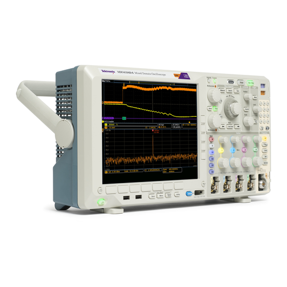
MSO4000B and DPO4000B Series
Digital Phosphor Oscilloscopes
Specifications and Performance Verification
ZZZ
Technical Reference
*P077050903*
077-0509-03
Table of
Contents
Previous
Page
Next
Page
1
2
3
4
5
Advertisement
Table of Contents
Need help?
Do you have a question about the MSO4000B Series and is the answer not in the manual?
Ask a question
Questions and answers
Related Manuals for Tektronix MSO4000B Series
Test Equipment Tektronix MDO4000B Series Program Manual
(1158 pages)
Test Equipment Tektronix MSO4000B Series User Manual
Digital phosphor oscilloscopes (229 pages)
Test Equipment Tektronix MSO4104B Service Manual
Mso4000b series, dpo4000b series, digital phosphor oscilloscopes (53 pages)
Test Equipment Tektronix MSO4000 Series Programmer's Manual
Digital phosphor (623 pages)
Test Equipment Tektronix MSO2000 series Instruction Manual
Demo 2 board (132 pages)
Test Equipment Tektronix DPO4104 Instructions Manual
4000 series declassification and security (13 pages)
Test Equipment Tektronix DPO4104 Demo Instruction Manual
4000 series (109 pages)
Test Equipment Tektronix DPO4034 User Manual
Digital phosphor oscilloscopes. mso4000 series; dpo4000 series (359 pages)
Test Equipment Tektronix MSO4034B Service Manual
Mso4000b series, dpo4000b series, digital phosphor oscilloscopes (53 pages)
Test Equipment Tektronix MSO 4 Series Manual
(43 pages)
Test Equipment Tektronix MSO4 Series Help Manual
(768 pages)
Test Equipment Tektronix MSO 4 Series Instructions Manual
Declassification and security. with option 4-sec enhanced security instrument (22 pages)
Test Equipment Tektronix MSO 4 Series Installation And Safety
(73 pages)
Test Equipment Tektronix 4 Series Declassification And Security Instructions
Mixed signal oscilloscopes (13 pages)
Test Equipment Tektronix MSO44B Quick Start Manual
B mixed signal oscilloscopes (272 pages)
Test Equipment Tektronix 4 Series Service Manual
(44 pages)
This manual is also suitable for:
Mso4104b-l
Mso4102b
Mso4104b
Dpo4000b series
Mso4102b-l
Dpo4102
...
Show all
Dpo4104b
Dpo4104b-l
Dpo4102b-l
Dpo4034b
Dpo4014b
Dpo4054b
Table of Contents
Print
Rename the bookmark
Delete bookmark?
Delete from my manuals?
Login
Sign In
OR
Sign in with Facebook
Sign in with Google
Upload manual
Upload from disk
Upload from URL


Need help?
Do you have a question about the MSO4000B Series and is the answer not in the manual?
Questions and answers