
Subscribe to Our Youtube Channel
Related Manuals for Emerson Control Link


Summary of Contents for Emerson Control Link
- Page 1 Control Link ACC Anti-Condensate Controller System Installation and Operation Manual 026-4704 Rev 6...
- Page 3 Emerson 1065 Big Shanty Road NW, Suite 100 Kennesaw, GA 30144 USA Phone 770-425-2724 Fax 770-425-9319...
-
Page 5: Table Of Contents
ETWORK AND AISY HAINING 7.4.1. Step 1: Disconnect Power to the Control Link ACC and Open the ACC Enclosure .......... 16 7.4.2. Step 2: Connect the MODBUS Network Cable....................16 7.4.3. Step 3: Set the Network Address ......................... 16 7.4.4. Step 4: Set the Network Baud Rate and MODBUS Parity ................. 17 7.4.5. - Page 6 10.4. P 4: FAIL: FLASH/CLK..........................29 RIORITY 10.5. P 5: FAIL: CONFIGURE..........................29 RIORITY 11 TROUBLESHOOTING CONTROL LINK ACCS AND THE ECT MODBUS NETWORK ......30 11.1. I ......................... 30 ONTROL FFLINE 12 SPECIFICATIONS ..............................31 13 PART NUMBERS AND DESCRIPTIONS ......................32 vi •...
-
Page 7: Overview
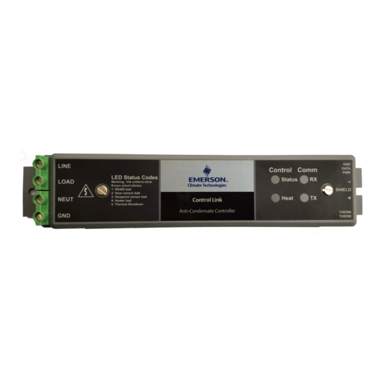
Control Link ACC: 815-6105) • UL Listed version 7A/10A (P/N 815-6100) The Control Link ACC (Figure 2-1) handles all • UL Recognized version 18A/26A/30A aspects of anti-sweat heater control and uses solid- (P/N 815-6105) - requires an additional heat sink state switching to control the heaters. -
Page 8: Dewpoint Sensor (P/N 814-6115)
3-pin connector that attaches the sensor (Figure 2-3). The door frame temperature Control Link ACC to the dewpoint sensor (use a sensor should be mounted to the coldest surface of the 3-wire 22AWG cable harness - Belden# 8771 ... -
Page 9: Mounting The Control Link Acc
Mounting the Control Link ACC The Control Link ACC is designed to be mounted in a case mullion, but may also be mounted in the raceway or in a metal electrical enclosure on the top of the case. Figure 3-1 shows examples of where the Control Link ACC may be mounted. -
Page 10: Calculating Maximum Ambient Temperature
Figure 4-1 - Ambient Temperature Calculation - additional heat sink For heater current greater than 10A, the heat sink of the Control Link ACC must be securely mounted against a large heat-conductive surface. Using thermal grease, the Control Link ACC has a metal back which acts as a heat sink, dissipating heat from the Triac that controls the heater. - Page 11 Figure 4-2 - Ambient Temperature Calculation - no external heat sink Door Frame Temperature Sensor (P/N 281-0002) Calculating Maximum Ambient Temperature • 5...
-
Page 12: Wiring The Control Link Acc
LOAD terminal and NEUTRAL side of the line voltage to the case door heater elements. All heater elements in the door frame and all doors of that frame should be connected in parallel to the Control Link ACC. Connect the GND terminal on the controller to Ground. -
Page 13: Mounting And Wiring The Sensors
Control Link ACC. DO NOT let any RTV sealants touch the sensor element and keep the sensor element as far as possible from RTV-sealed areas. -
Page 14: Note About Using Rtv Sealants
Figure 6-4. Insert the three wires on the other end of the cable to the matching 3-pin connector of the low voltage end of Control Link ACC by pressing in the orange tabs above the terminals using the small screwdriver. - Page 15 3-pin connector LOW VOLTAGE END BLACK DATA WHITE TEMP THERM THERM SENSOR 2-pin CABLE connector Dewpoint Sensor Wiring Figure 6-3 - Dewpoint Sensor Connector - ACC View Figure 6-4 - The Dewpoint Sensor Mounting and Wiring the Sensors • 9...
-
Page 16: Dewpoint Sensor Storage
— the sensor is placed under the door just to the left of the center mullion where the Control Link ACC is installed. Do not mount the sensor outside the case mullion - mount the sensor inside the case mullion. -
Page 17: Network Wiring And Configuration
E2 Modem/Expansion COM6 COM Card Mounted Above PIB RS232 7.2.1. Setup Network Ports COM3 Before setting up a Control Link ACC, the port on COM1 Plug-In Modem RS485 the E2 that has the MODBUS cable connected must Card be set up as a MODBUS port. -
Page 18: Add And Connect Control Link Accs - E2 Firmware Revision Prior To 2.8
COM ports on the E2. Highlight the COM port ECT Devices. Enter the number of ACC devices in connection field that will be used for Control Link, the CtrlLink ACC number field. and press - LOOK UP. From the list of ... - Page 19 Figure 7-5 - ACCs - E2 Firmware Version 2.8 and above 7. Repeat Steps 5 and 6 until each Control Link ACC device has a name and address. To enable communications between E2 and the 8. When finished, press to return to the Network Control Link units, the devices must be added and ...
- Page 20 A screen will open that will allow you set the address: List of MODBUS Devices Figure 7-10 - 8. Repeat Steps 5 and 6 until each Control Link ACC device has been commissioned. 9. When finished, press to return to the Network ...
-
Page 21: Wiring Types
You will see one of the following messages: 7.3. Wiring Types • Online - The Control Link ACC is communicating normally. Emerson specifies Belden #8761 shielded twisted • Offline - The Control Link ACC is not pair cables for use as MODBUS wiring (or Belden communicating, has not been commissioned, is not #82761 and Belden #88761 for plenum installations). -
Page 22: Modbus Network And Daisy-Chaining
Control Link ACC Network Connection Figure 7-13 - MODBUS network cable has two conductors plus a shield. For each Control Link ACC, connect the two Control Link ACC Daisy Chain Figure 7-12 - conductors to the 485 terminals of the MODBUS... -
Page 23: Step 4: Set The Network Baud Rate And Modbus Parity
Figure 7-15 - NOTE: If you are networking Control Link ACC only for purposes of sharing a dewpoint sensor, you do not need to set a baud rate or parity. Set all dip switches or jumpers to the DOWN (OFF) position. This will allow the Control Link ACC to share a dewpoint sensor as long as the network is physically present and terminated correctly. -
Page 24: Step 5: Terminate The End Devices
Switch/jumper 7 determines the baud rate at which DEVICE the controllers communicate. When switch/jumper 7 AT END OF is ON, the Control Link ACC will operate at 9600 DAISY-CHAIN baud. If switch/jumper 7 is OFF (default), the Control Link ACC will operate at 19200 baud. Switch/jumper SHIELD 8 determines the MODBUS network parity. -
Page 25: Step 7: Set The Setpoint Temperature Offset
You may specify how big this difference will 2. If sharing a dewpoint sensor, the remote offset is be by pressing the temperature offset button on the provided even if the Control Link ACC has its own dewpoint sensor. dewpoint sensor. - Page 26 If not, there may be a problem with MODBUS or dewpoint sensor wiring. • For Control Link ACCs that do not have dewpoint sensors directly connected to them, verify the Status LED is blinking once every 2 seconds to indicate status is OK.
-
Page 27: The Acc Hand-Held Terminal Interface
The ACC Hand- The RS-485 port supports the following: • Standard dumb terminal mode protocol Held Terminal • PL-430 version of I/O net Interface • I/O Net • MODBUS 8.2. Keys and Functions 8.1. HHT Hardware Functions Overview F1 Key Returns you to the Home Screen. -
Page 28: Hand Held Terminal Expansion Board
HHT port to view and set ACC information like a standard HHT • It can be used to update firmware for the attached Figure 8-3 - HHT Adaptor Board Connection to the ACC 22 • Control Link ACC I&O Manual 026-4704 Rev 6... -
Page 29: Hht Interface Navigation
ACC Start Screens ACC HHT MODE: Enter the mode where the MODBUS port runs the standard HHT dumb terminal protocol. CONTROL LINK ACC UPGRADE ACC FW: Upgrade the firmware of an 815 - 6100 ACC to the version loaded on the HHT. -
Page 30: Acc Status Screens
DUTY CYCLE%: 34 OVR: NO %: 00 OVR SRC: HHT SAVINGS%: 62 DUTY CYCLE%: The current output condition. OVR and %: Active heater output override (YES or NO) and percentage. 24 • Control Link ACC I&O Manual 026-4704 Rev 6... -
Page 31: The Main Selection Screen
8.5.6.3. The Main Selection Screen Board temperature will shutdown the output heater if greater than 212°F (100°C) SELECT:___1 Two modes can be selected for the temperature offset, Closed Loop, and Open Loop. 1: NETWORK 2: TEMP OFFSET Closed Loop 3: CTRL OPTIONS OFFSET SRC: REM Press down arrow past the Status Screen to access ACT OFFSET: 1.0... -
Page 32: Upgrading Acc Using Hht
Block number will update as blocks are sent to the ACC using the dip switches, the address cannot ACC. be changed with the HHT. The pre-set dip switches on the ACC will always take priority. 26 • Control Link ACC I&O Manual 026-4704 Rev 6... -
Page 33: Exit Hht Mode
8.5.9. Exit HHT Mode To exit a current mode on the HHT, unplug and reconnect (cycle power) or press down the F1 key for 6 seconds. This will return you to the HHT home screen where you can access the ACC-HHT Mode option. -
Page 34: Operation
Figure 9-1 - the heater will be 100% ON. A linear calculation is The Control Link ACC has four status LEDs that made between those limits: indicate what the controller is doing. They are: the red... -
Page 35: Tx And Rx Status Leds
9.1.3. TX and RX Status LEDs If the Control Link ACC is being networked with other Control Link ACCs via its MODBUS network connection, the TX and RX LEDs blink to indicate transmission and receipt of network messages. On a properly networked Control Link ACC, the RX LED should blink about once every 15 seconds. -
Page 36: Error Modes
10 Error Modes 10.3. Priority 3: FAIL: DEWPT The Control Link ACC has several error modes it Cannot communicate with the dewpoint sensor, will enter when failures occur. The controller has a and there is no dewpoint data being broadcast. The General Status LED that blinks at a 0.5 Hz (1 blink... -
Page 37: Troubleshooting Control Link Accs And The Ect Modbus Network
- Switches/jumpers 7 and 8 in the DOWN position specify 19.2k baud and no parity. If either of these switches/jumpers are not in the DOWN position, set them DOWN. If Control Link ACC is Offline Troubleshooting Control Link ACCs and the ECT MODBUS Network • 31... -
Page 38: Specifications
+/- 4°C (+/- 7.2°F) over RH of 10 to 40% RH Agency Approvals UL916 Open Energy Management Equipment, File E118489, FCC Part 15 Class A (non-intentional radiators), CE, RoHS Table 12-1 - Control Link ACC Specifications 32 • Control Link ACC I&O Manual 026-4704 Rev 6... -
Page 39: Part Numbers And Descriptions
281-0001 Door Frame Temperature Sensor (included with ACC Kits 1-4 listed below) 815-6101 ACC Kit (1) - Control Link ACC 10Amp and Door Frame Temp Sensor 815-6106 ACC Kit (2) - Control Link ACC 30Amp and Door Frame Temp Sensor... - Page 42 Emerson Climate Technologies Retail Solutions, Inc. and/or its affiliates (collectively “Emerson”), reserves the right to modify the designs or specifications of such products at any time without notice. Emerson does not assume responsibility for the selection, use or maintenance of any product. Responsibility for proper selection, use and maintenance of any product remains solely with the purchaser and end-user.
Need help?
Do you have a question about the Control Link and is the answer not in the manual?
Questions and answers