Table of Contents
Advertisement
Quick Links
Instruction Manual
D103576X012
January 2020
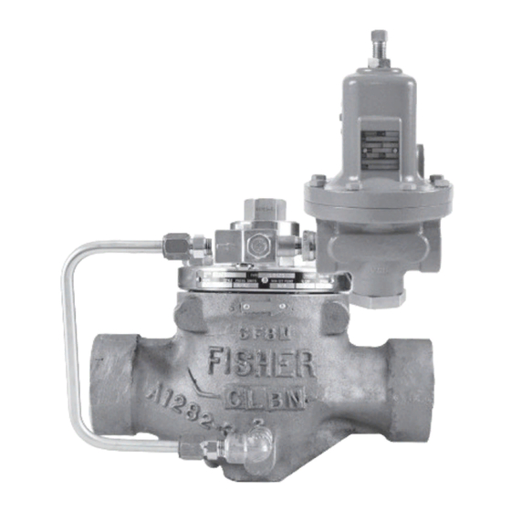
Type LR125 Pressure Reducing Liquid Regulator
TYPE LR125 REGULATOR
Figure 1. Type LR125 Pressure Reducing Liquid Regulator and Type MR95H/MR95HP Pilot
!
Failure to follow these instructions or
to properly install and maintain this
equipment could result in bursting
of the equipment and/or chemical
contamination causing property damage
and personal injury or death.
Fisher™ regulators must be installed,
operated and maintained in accordance
with federal, state and local codes, rules
and regulations and Emerson Process
Management Regulator Technologies,
Inc. (Emerson) instructions.
If the regulator discharges process
fluid or a leak develops in the system,
service to the unit may be required.
Failure to correct trouble could result in
a hazardous condition.
WARNING
TYPE MR95H/MR95HP PILOT
Call a qualified service person to service
the unit. Installation, operation and
maintenance procedures performed
by unqualified personnel may result
in improper adjustment and unsafe
operation. Either condition may result in
equipment damage or personal injury.
Only a qualified person must install or
service the regulator.
The Type LR125 is designed for liquid
service. Do not operate the regulator
in applications where temperatures are
below the process fluid's freezing point
or above its boiling point which are
dependent on the process fluid and the
application pressures.
Type LR125
Advertisement
Table of Contents

Related Manuals for Emerson Fisher LR125


Summary of Contents for Emerson Fisher LR125
- Page 1 Only a qualified person must install or operated and maintained in accordance service the regulator. with federal, state and local codes, rules and regulations and Emerson Process The Type LR125 is designed for liquid Management Regulator Technologies, service. Do not operate the regulator Inc.
-
Page 2: Specifications
Type LR125 Specifications Specifications for the Type LR125 regulator are shown below. Other information for the main valve appears on the nameplate. The control spring range for the pilot is marked on the nameplate of Type MR95H/MR95HP pilot. Main Valve Body Sizes, End Connection Styles Type LR125 Main Valve (continued) and Structural Design Ratings Bonnet Bushing: Stainless steel... -
Page 3: Principle Of Operation
Type LR125 Table 1. Type LR125 Main Valve Body Sizes, End Connection Styles, Structural Design Ratings and Maximum Operating Inlet Pressures STRUCTURAL DESIGN MAXIMUM OPERATING MAIN VALVE BODY SIZES MAIN VALVE BODY RATING INLET PRESSURE END CONNECTION STYLES MATERIAL psig psig NPT or SWE 1500... - Page 4 Type LR125 CONTROL SPRING TYPE 112 RESTRICTOR TYPE MR95H/MR95HP PILOT DIAPHRAGM VALVE PLUG SUPPLY LINE MAIN SPRING DIAPHRAGM AND PLUG ASSEMBLY INTERNAL STRAINER M1215 INLET PRESSURE OUTLET PRESSURE ATMOSPHERIC PRESSURE LOADING PRESSURE Figure 2. Type LR125 Operational Schematic...
- Page 5 Type LR125 BLOCK VALVE BLOCK VALVE INLET OUTLET HAND VALVE SUPPLY PRESSURE LINE CONTROL LINE ALTERNATE CONTROL LINE RESTRICTOR B2605_A TYPE MR95H/MR95HP PILOT TYPE MR95H/MR95HP PILOT INSTALLATION WITH PILOT EXHAUST INTO CONTROL LINE Figure 3. Typical Type LR125 Installation Schematic Table 2.
- Page 6 Type LR125 Table 3. Outlet (Control) Pressure Ranges OUTLET PRESSURE RANGE SPRING WIRE DIAMETER SPRING FREE LENGTH SPRING PART NUMBER PILOT AND COLOR psig 15 to 30 1.0 to 2.1 0.207 5.26 2.50 63.5 ERCA04288A0, Yellow Type MR95H 25 to 75 1.7 to 5.2 0.234 5.94...
-
Page 7: Startup And Adjustment
Type LR125 3. The standard pilot mounting position is as 8. Install a downstream pressure control line with shown in Figure 1. Other mounting positions a minimum size of 1/2 in. / 13 mm (as shown are available. in Figure 3) to the pilot control line or outlet connection. - Page 8 Regulator Performance Accuracy Hysteresis Type LR125 Stability Speed of Response (Demand Decrease) Speed of Response (Demand Increase) Increased Performance Decreased Performance LOADING CONNECTION: 1/4 NPT PIPE CONNECTS TO TYPE LR125 DIAPHRAGM LOADING PORT PILOT SUPPLY CONNECTION: 1/4 NPT PIPE 112 Restrictor Adjustment Guide CONNECTS TO UPSTREAM PILOT SUPPLY TAP OUTLET CONNECTION: 1/4 NPT PIPE CONNECTS TO PILOT INLET CONNECTION...
-
Page 9: Maintenance
The “0” setting has the smallest necessary. Due to the care Emerson takes in meeting (minimum) flow passage; at no point of rotation will the all manufacturing requirements (heat treating, Type 112 restrictor be completely shut off. - Page 10 Type LR125 DIAPHRAGM (KEY 9) BOTTOM PLUG (KEY 11) TOP PLUG O-RING (KEY 14) FLANGED HEX NUT (KEY 13) O-RING TOP PLUG (KEY 5) (KEY 70) O-RING (KEY 10) W7394 Figure 6. Diaphragm and Plug Assembly Components 7. If travel indicator was removed, lightly lubricate CAUTION the travel indicator assembly threads (key 19) and screw it into the bonnet (key 2).
- Page 11 Type LR125 INDICATOR FITTING MAIN SPRING UPPER SPRING (KEY 12) (KEY 19) SEAT (KEY 17) INDICATOR STEM O-RING (KEY 15) (KEY 18) HEX NUTS INDICATOR COVER (KEY 4) (KEY 21) BACK-UP RINGS (KEY 16) INDICATOR O-RING (KEY 6) INDICATOR W7400_1 WASHER (KEY 20) Figure 7.
- Page 12 (key 12). This allows proper positioning service. Only parts manufactured by of the diaphragm to permit full travel of the valve Emerson should be used for repairing plug (key 4). Torque diaphragm cap screws per Fisher™ regulators. Table 10. Complete reassembly procedures and turn the adjusting screw (key 15) to produce the desired outlet pressure.
- Page 13 Type LR125 W4573 Figure 8. Pushing Groove Valve Up With Retainer ELASTOMER/FABRIC MATERIAL CODE YEAR OF MANUFACTURE THICKNESS CODE RADIAL LOCATION TO LOCATE IMPRINT CODE LOCATE INK CODE DOME IDENTIFICATION BETWEEN RADII MATERIAL THICKNESS INK CODE INK CODE (USE ONE LOCATION ONLY) MANUFACTURER CODE Figure 9.
- Page 14 Type LR125 Table 8. Troubleshooting Guide ISSUE POSSIBLE SOLUTION • If travel indicator is in UP position, check restrictor and pilot supply filter for plugging. Outlet pressure suddenly rises above setpoint and approaches inlet pressure • If travel indicator is in DOWN position, check main valve for debris or diaphragm damage. •...
- Page 15 Type LR125 Table 11. Type LR125 Main Valve Body Part Numbers (Key 1, Figure 10) BODY SIZES, BODY MATERIAL END CONNECTION STYLE PART NUMBER In. / DN GE11581X012 GE11440X012 CL150 RF GE11583X012 WCC Steel CL300 RF GE11607X012 CL600 RF GE11608X012 PN 16/25/40 RF GE13625X012 1 / 25...
-
Page 16: Parts Ordering
Type LR125 Parts Ordering Type 112 Restrictor Maintenance When corresponding with your local Sales Office about WARNING this equipment, reference the equipment serial number or FS number found on a nameplate attached to the Avoid personal injury or damage to bonnet. - Page 17 Type LR125 Type LR125 Main Valve Description Part Number (Figures 10 to 14) (continued) Top Plug O-ring 1 and 2 in. / DN 25 and 50 bodies Nitrile (NBR) 13A1584X052 Description Part Number Fluorocarbon (FKM) 13A1584X022 O-ring 3 and 4 in. / DN 80 and 100 bodies 1 and 2 in.
- Page 18 Type LR125 Type LR125 Main Valve Type MR95H/MR95HP Pilot (Figures 10 to 14) (continued) (Figure 15) (continued) Description Part Number Description Part Number Pipe Nipple Stem Assembly, Stainless steel ERAA01904A0 Steel - - - - - - - - - - - Stem Guide Bushing, Stainless steel ERCA03694A0 Stainless steel...
- Page 19 Type LR125 49B6019_A MAIN VALVE ASSEMBLY FOR 1 IN. / DN 25 BODY SIZE APPLY LUBRICANT L1 = LITHIUM POLYMER TYPE LUBRICANT (MULTI-PURPOSE GREASE) L2 = ANTI-SEIZE LUBRICANT 1. Lubricants must be selected such that they meet the temperature requirements. Figure 10.
- Page 20 Type LR125 48B2142_C MAIN VALVE ASSEMBLY FOR 2, 3 AND 4 IN. / DN 50, 80 AND 100 BODY SIZES APPLY LUBRICANT / SEALANT L1 = LITHIUM POLYMER TYPE LUBRICANT (MULTI-PURPOSE GREASE) L2 = ANTI-SEIZE LUBRICANT S = MEDIUM STRENGTH THREADLOCKER 1.
- Page 21 Type LR125 48B2142_C TOP PLUG (KEY 5) Figure 11. Type LR125 Nameplate and Flow Arrow O-RING (KEY 14) O-RING (KEY 70) DIAPHRAGM (KEY 9) BOTTOM PLUG (KEY 11) O-RING (KEY 10) 19B2408 LOCK WASHER (KEY 130) SOCKET HEAD SCREW (KEY 129) Figure 12.
- Page 22 Type LR125 GF04914 APPLY LUBRICANT / SEALANT L1 = GENERAL PURPOSE PTFE OR LITHIUM GREASE L2 = ANTI-SEIZE COMPOUND 1. Lubricant and sealant must be selected such that they meet the temperature requirements. 2. Apply L2 (anti-seize compound) on key 16 for Stainless steel bolts. Figure 15.
- Page 23 Type LR125 20B4393-E APPLY LUBRICANT / SEALANT S = THREAD SEALANT L = ANTI-SEIZE LUBRICANT 1. Lubricant and sealant must be selected such that they meet the temperature requirements. Figure 16. Type 112 Restrictor TYPE MR95H/MR95HP PILOT TYPE 112 RESTRICTOR ERAA00986_B Figure 17.
- Page 24 Technologies, Inc. All rights reserved. 01/20. Emerson Automation Solutions The Emerson logo is a trademark and service mark of Emerson Electric Co. All other marks are the property of their prospective owners. Fisher™ is a mark owned by Fisher Controls International LLC, a business...
Need help?
Do you have a question about the Fisher LR125 and is the answer not in the manual?
Questions and answers