Sign In
Upload
Manuals
Brands
Emerson Manuals
Controller
Control Link
Emerson Control Link Manuals
Manuals and User Guides for Emerson Control Link. We have
1
Emerson Control Link manual available for free PDF download: Installation And Operation Manual
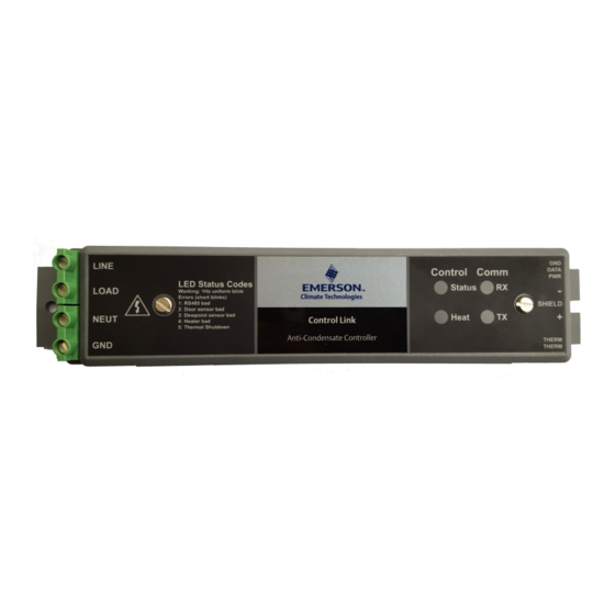
Emerson Control Link Installation And Operation Manual (42 pages)
ACC Anti-Condensate Controller System
Brand:
Emerson
| Category:
Controller
| Size: 5.68 MB
Table of Contents
Table of Contents
5
1 Overview
7
2 Components
7
Control Link Acc (P/N S 815-6100 and 815-6105)
7
Dewpoint Sensor (P/N 814-6115)
8
Door Frame Temperature Sensor (P/N 281-0002)
8
3 Mounting the Control Link Acc
9
4 Calculating Maximum Ambient Temperature
10
5 Wiring the Control Link Acc
12
Power and Heater Element Wiring
12
Ratings and Current Protection
12
6 Mounting and Wiring the Sensors
13
The Dewpoint Sensor
13
Placement
13
Note about Using RTV Sealants
14
Dewpoint Sensor Mounting Dimensions
14
Dewpoint Sensor Wiring
14
Dewpoint Sensor Storage
16
The Door Frame Temperature Sensor
16
Placement
16
7 Network Wiring and Configuration
17
Network Connection to E2
17
E2 Setup of Control Link Acc Devices
17
Setup Network Ports
17
Add and Connect Control Link Accs - E2 Firmware Revision Prior to 2.8
18
Wiring Types
21
MODBUS Network and Daisy-Chaining
22
Step 1: Disconnect Power to the Control Link ACC and Open the ACC Enclosure
22
Step 2: Connect the MODBUS Network Cable
22
Step 3: Set the Network Address
22
Step 4: Set the Network Baud Rate and MODBUS Parity
23
Step 5: Terminate the End Devices
24
Termination Block Network
24
Step 6 - Connect a Dewpoint Sensor to Control Link ACC(S) on the Network
24
Step 7: Set the Setpoint Temperature Offset
25
Step 8 - Network Configuration Is Complete - Restore Power to the ACC
25
8 The Acc Hand-Held Terminal Interface
27
Hht Hardware Overview
27
Keys and Functions
27
Hand Held Terminal Expansion Board
28
Connecting the Hht Adapter Board
28
HHT Home Screen
28
Hht Interface Navigation
29
ACC HHT Network Setup
29
Modes of ACC Addressing
29
The ACC HHT Interface
29
ACC Start Screens
29
ACC Status Screens
30
Input Status Screen
30
Output Status Screen
30
ACC Configuration Screens
30
HHT Changes When ACC Is Connected to E2
30
HHT Changes When ACC Is Stand-Alone
30
The Main Selection Screen
31
Upgrading ACC Using HHT
32
Changing ACC Address Using HHT
32
Exit HHT Mode
33
9 Operation
34
Control Link ACC Status Leds
34
Heater Status LED
34
General Status LED
34
TX and RX Status Leds
35
10 Error Modes
36
Priority 1: Fail: over Temp
36
Priority 2: Fail: Temp Sens
36
Priority 3: Fail: Dewpt Sns
36
Priority 4: Fail: Flash/Clk
36
Priority 5: Fail: Configure
36
11 Troubleshooting Control Link Accs and the Ect Modbus Network
37
I Fcontrol Link Acc Is Offline
37
12 Specifications
38
13 Part Numbers and Descriptions
39
Advertisement
Advertisement
Related Products
Emerson Liebert AC8
Emerson Control Link ACC
Emerson Liebert PEX+ Series
Emerson Asco Sentronic LP 617 Series
Emerson Fisher L2sj
Emerson Fisher LS220
Emerson Fisher LS224
Emerson Fisher LS250
Emerson Fisher LS254
Emerson Fisher LS200 Series
Emerson Categories
Controller
Control Unit
Transmitter
Measuring Instruments
Fan
More Emerson Manuals
Login
Sign In
OR
Sign in with Facebook
Sign in with Google
Upload manual
Upload from disk
Upload from URL