Table of Contents
Advertisement
Instruction Manual
D103032X012
Fisherr L2 Liquid Level Controller
Contents
. . . . . . . . . . . . . . . . . . . . . . . . . . . . . . . . .
. . . . . . . . . . . . . . . . . . . . . . . . . . . . .
. . . . . . . . . . . . . . . . . . . . . . . . . . . . . . . . .
. . . . . . . . . . . . . . . . . . . . . . . . . . . . . . .
. . . . . . . . . . . . . . . . . . . . . . . . . . .
. . . . . . . . . . . . . . . . . . . . . . . . . . . . . . . . . .
. . . . . . . . . . . . . . . . . . . . . . . .
. . . . . . . . . . . . . . . . . . . . . . . . . . . . . . . . . . . . . . .
. . . . . . . . . . . . . . . . . . . . . . .
. . . . . . . . . . . . . . . . . . . . . . . . . . . . .
. . . . . . . . . . . . . . . . . . . . . . . . . . .
. . . . . . . . . . . . . . . . . . . . . . . .
. . . . . . . . . . . . . . . . . . . . . . . . . . . . . . . .
. . . . . . . . . . . . . . . . . . . . . . . . . . . .
. . . . . . . . . . . . . . . . . . . . . . . . . . . . . .
Introduction
Scope of Manual
This instruction manual includes installation, adjustment, maintenance, and parts ordering information for the Fisher
L2 liquid level controller.
Do not install, operate or maintain an L2 Liquid Level Controller without being fully trained and qualified in valve,
actuator, and accessory installation, operation, and maintenance. To avoid personal injury or property damage, it is
important to carefully read, understand, and follow all contents of this manual, including all safety cautions and
warnings. If you have any questions about these instructions, contact your
before proceeding.
www.Fisher.com
1
1
3
3
3
4
. . . . . . . . . . . . . . . . . . .
4
. . . . . . . . . . . . . . . . .
4
. . . . . . . . . . . . .
5
5
6
. . . . . . . . . . . . .
6
. . . . . . . . . . . . . .
6
6
8
8
. . . . . . . . . . . .
9
. . . . . . . . . . .
9
. . . . . . . . . . . . . . . . . . . .
9
. . . . . . . . . . . . . . . . . . . .
9
10
11
. . . . . . . .
11
. . . . . . . . . . . . . . . . .
11
11
13
. . . . . . . . . . . . . . . .
13
. . . . . . . . . .
13
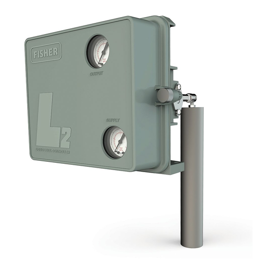
Figure 1. Fisher L2 Liquid Level Controller
W8418-1
. . . . . . . . . . . . . . . . . . . . . . . . . .
. . . . . . . . . . . . . . . . . . . . . . . . . . . . . . .
. . . . . . . . . . . . . . . . . . . . . . . . . . . . . . . . . . .
. . . . . . . . . . . . . . . . . . . . . . . . . . . . . . . . . . .
. . . . . . . . . . . . . . . . . . . . . . . . . . . . . . . . .
. . . . . . . . . . . . . . . . . . . . . . . . . . . . . . . . . . . .
Emerson Process Management sales office
L2 Controller
July 2015
14
14
14
14
14
16
Advertisement
Table of Contents

Related Manuals for Emerson Fisher L2


Summary of Contents for Emerson Fisher L2
-
Page 1: Table Of Contents
Fisherr L2 Liquid Level Controller Contents Figure 1. Fisher L2 Liquid Level Controller Introduction ....... . . - Page 2 Instruction Manual L2 Controller July 2015 D103032X012 Table 1. Specifications Available Configurations between 1.4 and 5.2 bar (20 and 50 psig) direct, and 1.4 bar and 2.4 bar (20 and 35 psig) reverse Controller: Snap‐acting or throttling Sensor: Displacer‐type liquid level sensor for Do not use supply pressure below 1.4 bar (20 psig) mounting to side of tank.
-
Page 3: Description
2. Depends on float rod/displacer orientation and length. Contact your Emerson Process Management sales office before proceeding for further information. 3. Minimum specific gravity differential with standard displacer is 0.4. Minimum specific gravity differential of 0.1 is possible with special displacer, consult your Emerson Process Management sales office for displacer sizing information. -
Page 4: Installation
Instruction Manual L2 Controller July 2015 D103032X012 Installation WARNING Always wear protective clothing, gloves, and eyewear when performing any installation operations to avoid personal injury. To avoid personal injury or property damage caused by the sudden release of process fluid, be certain the service conditions do not exceed the sensor pressure limits. -
Page 5: Attaching The Sensor To The Vessel
While use and regular maintenance of a filter that removes particles larger than 40 micrometers in diameter will suffice in most applications, check with an Emerson Process Management field office and industry instrument air quality standards for use with corrosive air or if you are unsure about the proper amount or method of air filtration or filter maintenance. -
Page 6: Vent
Instruction Manual L2 Controller July 2015 D103032X012 Vent WARNING If a flammable or hazardous gas is to be used as the supply pressure medium, personal injury or property damage could result from fire or explosion of accumulated gas or from contact with hazardous gas. The controller/actuator assembly does not form a gas‐tight seal, and when the assembly is enclosed, a remote vent line, adequate ventilation, and necessary safety measures should be used. - Page 7 Instruction Manual L2 Controller D103032X012 July 2015 Figure 3. Fisher L2 Throttling and On/Off Controller Switch Positions for Changing Action and Control Mode SWITCH RETENTION SCREWS SWITCH RETENTION SCREWS DIRECT ACTION THROTTLING DIRECT ACTION ON/OFF CONTROL MODE CONTROL MODE REVERSE ACTION ON/OFF...
-
Page 8: Span Adjustment
Instruction Manual L2 Controller July 2015 D103032X012 Span Adjustment Except where indicated, key numbers referenced in the following procedures are shown in figure 8. The span levers and other proportional band information are shown in figure 5. Figure 5. Proportional Band Adjustments LEVER A SPAN LEVER GAP LEVER B... -
Page 9: Direct-Acting Throttling Controllers
Instruction Manual L2 Controller D103032X012 July 2015 5. Check figures 3 and 4 for correct control action and control mode. 6. Adjust the relay adjustment screw (key 49, throttling controller) or the valve assembly (key 51, snap‐acting controller) so that the gap between the span levers (see figure 5) is equal when lever A is contacting the displacer rod. -
Page 10: Principle Of Operation
Instruction Manual L2 Controller July 2015 D103032X012 Principle of Operation The operation of L2 controllers in combination with the sensor is based on Archimedes Principle, which states that a body immersed in a liquid will be buoyed up by a force equal to the weight of the liquid displaced. The buoyant force and resultant movement of the displacer in the liquid is transmitted to the controller which delivers a pneumatic signal to a control valve. -
Page 11: Maintenance
Instruction Manual L2 Controller D103032X012 July 2015 Maintenance Parts are subject to normal wear and must be inspected periodically and replaced as necessary. The frequency of parts inspection and replacement depends upon the severity of service conditions. When inspection or repairs are required, disassemble only those parts necessary to accomplish the task. - Page 12 Instruction Manual L2 Controller July 2015 D103032X012 4. Slide the pivot base (key 73), retaining ring (key 76), anti‐extrusion ring (key 75), and O‐ring (key 74) off the displacer rod. Remove the O‐ring (key 77) and backup ring (key 78) from the pivot base. Figure 7.
-
Page 13: Assembly
Instruction Manual L2 Controller D103032X012 July 2015 Assembly WARNING Improper assembly of the O‐rings, anti‐extrusion ring, and backup ring could result in O‐ring extrusion and permit leakage of process fluids. To avoid personal injury or property damage from leaking process fluid, be sure the O‐rings, anti‐extrusion ring and backup ring are assembled in the order shown in figure 7. -
Page 14: Related Documents
D Converting a Threaded NPT Connection to a Flange Connection—Supplement to Fisher L2 and L2sj Liquid Level Controller Instruction Manuals (D103277X012) D Dimensions for NPS 2 CL150 through 1500 Slip On Flange Connections—Supplement to Fisher L2 and L2sj Liquid Level Controller Instruction Manuals (D103405X012) D Fisher L2sj Low Emission Liquid Level Controller Instruction Manual (D103216X012) - Page 15 Instruction Manual L2 Controller D103032X012 July 2015 Figure 8. Fisher L2 Liquid Level Controllers THROTTLING AND ON/OFF CONTROLLER RELAY ASSY THROTTLING AND ON/OFF CONTROLLER SNAP‐ACTING CONTROLLER RELAY ASSEMBLY VIEW A‐A SNAP‐ACTING CONTROLLER APPLY LUB/SEALANT GB0137-D...
-
Page 16: Sensor
Responsibility for proper selection, use, and maintenance of any product remains solely with the purchaser and end user. Fisher is a mark owned by one of the companies in the Emerson Process Management business unit of Emerson Electric Co. Emerson Process Management, Emerson, and the Emerson logo are trademarks and service marks of Emerson Electric Co.
Need help?
Do you have a question about the Fisher L2 and is the answer not in the manual?
Questions and answers