Table of Contents
Advertisement
Quick Links
Instruction Manual
Form 1013
December 2005
2500 and 2503 Series Level-Trol
and Transmitters
Contents
. . . . . . . . . . . . . . . . . . . . . . . . . . . . . . .
. . . . . . . . . . . . . . . . . . . . . . . . .
. . . . . . . . . . . . . . . . . . . . . . . . . . . . . .
. . . . . . . . . . . . . . . . . . . . . . . . . . . .
. . . . . . . . . . . . . . . . . . . . . . . . . . . . . . . . . .
. . . . . . . . . . . . . . . . . . . . . . . . .
. . . . . . . . . . . . . . . . . . . . . . . . . . . . . . . .
. . . . . . . . . . . . . . . . . . . . . . . .
. . . . . . . . . . . . . . . . . . . . . . . .
Type 2500 Controller or Type 2500T
. . . . . . . . . . . . . . . . . . . . . . . . . . .
. . . . . . . . . . . . . . . . . . . . . . . . . . . .
. . . . . . . . . . . . . . . . . . . . . . . . . .
. . . . . . . . . . . . . . . . . . . . . . . . . . . . . . . .
. . . . . . . . . . . . . . . . . . . . . . . . .
. . . . . . . . . . . . . . . . . . . . . . . . .
. . . . . . . . . . . . . . . . . . . . . . . .
www.Fisher.com
. . . . . . . . . . . . . . . . . . . . . .
. . . . . . . . . . .
. . . . . . . . . . . . . . . . . . .
. . . . . . . . . . . . . . . .
. . . . . . . . . . . . . . . . . . . .
. . . . . . . . . . . . . . . . . . . .
. . . .
. .
. . . . . . . . . . . . . . . . . . .
. . . . . . . . . . . . . . . . . . . . .
. . . . . . .
. . . . . .
. . . . . . . . . . . . . . . . . . .
. . . . . . . . . . . . . . . . . . .
. . . . . . . . . . . . . .
. . . . . . . . . . . . . . . . . . .
. . . . . . . . . . . . . . . . . . . .
. . . . . . . . . . . . . . . . . . .
. . . . . . . .
2
2
2
2
2
5
5
6
6
7
8
8
8
10
10
12
12
13
14
14
15
W8334
15
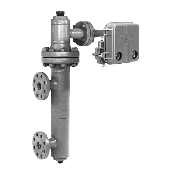
Figure 1. 2500 or 2503 Series Level-Trol
15
Transmitter on Caged 249 Series Sensor
15
. . . . . . . . . . . . . . . . . . . . . . . . . . . . . . . . . . . .
15
15
15
15
Type 2500 Controller or Type 2500T
16
16
16
16
17
18
19
Type 2500
R
Controllers
2500 OR 2503 SERIES
CONTROLLER/
TRANSMITTER
249 SERIES SENSOR
. . . . . . . . . . . . . . . . . . . . .
. . . . . . . . . . . . . . . . . .
. . . . . . . . . . . . . . . . . . .
. . . . . . . . . . . . . . . . . . . . .
. . . . . . . . . . . . . . . . . . . . .
. . . . . . . . . . . . . . . . . . . . . . . . . . .
. . . . . . . . . . . . . . . . . . . . . . .
. . . . . . . . . . . . . . . . . . .
. . . . . . . . . . . . . . . . . . . . .
. . . . . . . . . . . . . . . . . . . . . . . . . . . . .
. . . . . . . . . . . . . . . . . . . . . . . . .
. . . . . . . . . . . . . . . . . . . . . . . . . . . . . . .
. . . . . . . . . . . . . .
(continued on page 2)
R
Controller/
20
20
21
21
21
21
21
23
23
23
24
24
26
26
. .
27
Advertisement
Table of Contents

Related Manuals for Emerson Level-Trol 2500 Series


Summary of Contents for Emerson Level-Trol 2500 Series
-
Page 1: Table Of Contents
Instruction Manual Form 1013 Type 2500 December 2005 2500 and 2503 Series Level-Trol Controllers and Transmitters Contents Introduction ....... Scope of Manual . -
Page 2: Introduction
D carefully reading and Responsibility for the selection, use, understanding the contents of this manual. If you and maintenance of any product have any questions about these instructions, contact remains with the purchaser and your Emerson Process Managementt sales office. end-user. - Page 3 Instruction Manual Form 1013 Type 2500 December 2005 Table 1. Specifications Available Configurations integrally mounted Type 67FR filter/regulator, typical supply pressure to the regulator is from 2.5 Type 2500—Proportional-Only controller bar (35 psig) to 17 bar (250 psig), maximum. For Type 2500C—Proportional-Only controller with supply pressures to the filter/regulator, refer to the indicator (see figure 10)
- Page 4 42 scfh 3 bar (45 psig) 1. Consult your Emerson Process Management sales office about gauges in other units. 2. Control and stability may be impaired if this pressure is exceeded. 3. At zero or maximum proportional band or specific gravity setting.
-
Page 5: Installation
N06600, N10276 may result from fire or explosion if 1. N05500 is not recommended for spring applications above 232_C (450_F). Contact your Emerson Process Management natural gas is used as the supply sales office or application engineer if temperatures exceeding this medium and preventative measures limit are required. -
Page 6: Uncrating
Instruction Manual Form 1013 Type 2500 December 2005 sudden release of the pressure. DISPLACER Contact with hazardous fluid, fire, or explosion can be caused by CAGE puncturing, heating, or repairing a displacer retaining process pressure or fluid. This danger may not be readily apparent when disassembling the sensor assembly or removing the displacer. -
Page 7: Mounting Caged Sensor
Instruction Manual Form 1013 Type 2500 December 2005 AH9150−A A1271−2/IL A2613−2/IL Figure 5. Cage Connection Styles Figure 4. Cage Head Mounting Positions Cage connections normally are either 1-1/2 or 2-inch, screwed or flanged. Figure 5 shows the combinations. With flanged connections, use Mounting Caged Sensor standard gaskets or other flat-sheet gaskets compatible with the process fluid. -
Page 8: Mounting Cageless Sensor
Instruction Manual Form 1013 Type 2500 December 2005 Note If the controller/transmitter is not mounted on the sensor, refer to the EQUALIZING LINE Installing Controller/Transmitter on Sensor procedures in the Maintenance section. This section also provides instructions for adding a heat insulator to a unit. - Page 9 Instruction Manual Form 1013 Type 2500 December 2005 MOUNTED SIDE MOUNTED CF5380-A A3893/IL W0645−1/IL SIDE VIEW (SHOWING STILLWELL) SIDE VIEW (WITHOUT STILLWELL) Figure 7. Cageless Sensor Mounting DISPLACER STEM END PIECE DISPLACER ROD DISPLACER COTTER SPRING DISPLACER STEM COTTER SPRING SPUD EXTENSION LOCKING NUTS...
-
Page 10: Supply And Output Pressure Connection
Instruction Manual Form 1013 Type 2500 December 2005 through the sensor head access hole after the OPTIONAL HEAT sensor is installed on the vessel. Connect the INSULATOR EXTENSION displacer as shown in figure 8, locking the assembly with the cotter springs provided. If a stem extension 223.8 176.3 8.81... - Page 11 Instruction Manual Form 1013 Type 2500 December 2005 W0641−1B/IL 1C9283−B/DOC BOURDON TUBE DETAIL OF TYPE 2500S ON−OFF RAISE LEVEL DIAL FOR CONTROLLER LEFT−HAND MOUNTING LEVEL SET ARM 3−WAY VALVE LEVEL ADJUSTMENT MOUNTING SCREWS FLAPPER ALIGNMENT SCREW NOZZLE PROPORTIONAL LEVEL SET SHAFT CLAMP NUT PLUNGER BAND ADJUSTMENT...
-
Page 12: Controller/Transmitter Output Connection
Instruction Manual Form 1013 Type 2500 December 2005 D make sure there is no process flow through the final control element, or D disconnect the controller/transmitter output signal line and connect it to a pressure gauge. During prestartup, the displacer must be positioned from its maximum to its minimum range of operation. -
Page 13: Transmitter
Instruction Manual Form 1013 Type 2500 December 2005 determine the proper dial setting on the horizontal 0.4 to 2 bar (6 to 30 psig) output pressure range. If axis. the pressure is incorrect, loosen the locknut of the Type 67FR filter/regulator (figure 9); turn the adjusting screw clockwise to increase the pressure D Sensor with Nonstandard Torque Tube or, counterclockwise to decrease the pressure. -
Page 14: Type 2500S Controller
Instruction Manual Form 1013 Type 2500 December 2005 Type 2500S Controller 8. If all prestartup checks are satisfactory, proceed to the Startup section. If performance is unsatisfactory, proceed to the Calibration section. Note In the following steps the output Type 2503 Controller pressure can go as high as the controller supply pressure. -
Page 15: Adjustments
Instruction Manual Form 1013 Type 2500 December 2005 b. For reverse-acting controllers, set it between procedure is the same for either direct or reverse 3.5 and 4.0. action. Tighten the knurled screw. 4. The OUTPUT gauge should read 0 bar (0 psig) for direct or full supply pressure for reverse action. -
Page 16: Wet Calibration
Type 2500 December 2005 Note release any pressure that may be in the vessel before removing the sensor Contact your Emerson Process assembly. Management sales office for information on obtaining the When removing the displacer from the displacer rod Supplement to 249 Series Sensors... -
Page 17: Calibration Procedure
Instruction Manual Form 1013 Type 2500 December 2005 Table 5. Minimum and Maximum Limits for Setting Process Variables APPLICATION MINIMUM LIMIT MAXIMUM LIMIT Liquid Level Displacer must be completely out of liquid Displacer must be completely submerged in liquid Interface Displacer must be completely submerged in lighter of two Displacer must be completely submerged in process liquids... -
Page 18: Type 2500 Controller And 2500T Transmitter
Instruction Manual Form 1013 Type 2500 December 2005 Table 6. Recommended Settings For Pre-Startup Checks RECOMMENDED RAISE LEVEL SETTING RECOMMENDED ZERO ADJUSTMENT SETTING FOR FOR TYPE 2500 CONTROLLER TYPE 2500T TRANSMITTER MOUNTING ACTION For Predetermined For Predetermined For Predetermined For Predetermined PROPORTIONAL BAND PROPORTIONAL BAND SPECIFIC GRAVITY Dial... -
Page 19: Type 2500S And 2503 Controllers
Instruction Manual Form 1013 Type 2500 December 2005 D For Reverse Acting Type 2500, 2500T, 0.2 D If the output pressure span is too large, slightly bar (3 psig) for a 0.2 to 1.0 bar (3 to 15 psig) output increase the PROPORTIONAL BAND or SPECIFIC or 0.4 bar (6 psig) for a 0.4 to 2.0 bar (6 to 30 psig) GRAVITY setting. -
Page 20: Startup
Instruction Manual Form 1013 Type 2500 December 2005 loosen the hex nut (key 40, figure 16) and rotate the D To decrease the differential gap, slide the flapper assembly about the torque tube shaft. For flexure strip base away from the torque tube shaft. fine flapper adjustment, turn the flapper alignment D To increase the differential gap, slide the screw (key 33, figure 16). -
Page 21: Type 2500T Transmitter
Instruction Manual Form 1013 Type 2500 December 2005 Principle of Operation 2. If desired, adjust the proportional band to the narrowest (lowest) setting that maintains stable The controller/transmitter receives the change in control. Proportional band adjustments will affect the fluid level, fluid-to-fluid interface level, or density process level and may require a level adjustment. - Page 22 Instruction Manual Form 1013 Type 2500 December 2005 CD2114−E BO998−1/IL Figure 12. Direct-Acting, Right-Hand-Mounted 2500-249 Series Controller/Transmitter closes the inlet end and opens the exhaust end of The proportional valve varies the reaction of the the relay valve which allows output pressure to Bourdon tube to changes in the output pressure.
-
Page 23: Proportional Valve
Instruction Manual Form 1013 Type 2500 December 2005 BD4466−A CD2114−E A1890−1/IL Figure 13. Direct-Acting Left-Hand-Mounted Type 2503 Controller Proportional Valve Type 2500S Controller This construction has the same flapper, relay, and proportional valve as the Type 2500 controller. The three-way proportional valve is adjustable to However, the nozzle is connected (figure 12) in such allow some or all of the output pressure change to a way that output pressure feedback (from the... -
Page 24: Maintenance
Instruction Manual Form 1013 Type 2500 December 2005 pressure or completely closes the relay valve for full When replacing the sensor assembly, exhaust of the output pressure, allowing no the displacer may retain process fluid in-between throttling. or pressure. Personal injury or property damage may occur due to For a direct-acting controller, as long as the process sudden release of the pressure. - Page 25 Instruction Manual Form 1013 Type 2500 December 2005 Table 7. Troubleshooting Chart for 2500 Series Controller/Transmitters FAULT POSSIBLE CAUSE CHECK CORRECTION 1. Process wanders or cycles 1.1 Proportional band or specific Ensure the prestartup procedures If stable control cannot be attained around set point.
-
Page 26: Removing Controller/Transmitter From Sensor
Instruction Manual Form 1013 Type 2500 December 2005 Removing Controller/Transmitter from Sensor WARNING To avoid injury in the following steps, turn off the supply pressure and carefully release any pressure trapped in the controller/transmitter before breaking any pressure connection. Provide a bypass for the control device if continuous operation is required during maintenance. -
Page 27: Installing Controller/Transmitter On Sensor
Instruction Manual Form 1013 Type 2500 December 2005 249 Series sensor, remove the torque tube arm from with four button head cap screws and washers (keys the sensor or vessel and reinstall the torque tube 40 and 53). Tighten the screws. arm in the opposite position according to the appropriate instruction manual. -
Page 28: Changing Action
Instruction Manual Form 1013 Type 2500 December 2005 AC9554 AR8148 BO996−1/IL Figure 15. Bourdon Tube-Flapper Arrangements for Various Actions and Mountings Changing Action 0.2 to 1 bar or 0 to 1.4 bar (3 to 15 psig or 0 to 20 psig) range. -
Page 29: Relay Deadband Testing (Type 2500 Controller Or 2500T Transmitter Only)
Calibration section. plug, and install the appropriate adjustment assembly. Parts Ordering Replacing the Proportional Valve Whenever corresponding with your Emerson Process Management sales office about this equipment, use the controller/transmitter type Note number and the serial number. The serial number is found on the nameplate (key 215, figure 16). -
Page 30: Parts List
Type 2500 December 2005 Note Description Part Number Retaining ring, pl steel (2 req’d) 1A465828992 Neither Emerson, Emerson Process Gauge glass (2 req’d) 0T019206042 Management, Fisher nor any of their Gauge glass gasket, chloroprene affiliated entities assumes (2 req’d) 0T019104082... - Page 31 Instruction Manual Form 1013 Type 2500 December 2005 LEVEL SET MOUNTING SCREWS SEE VIEW A 30A8865−D/DOC TYPICAL CONTROLLER 30A8866−C/DOC TYPE 2503R CONTROLLER CONSTRUCTION 30A8869−D/DOC NOTE: DETAIL OF INDICATOR PARTS NOT SHOWN 4, 24, 38, 39, 47, AND 48. ASSEMBLY ON C VERSIONS Figure 16.
- Page 32 *Recommended spare parts Level-Trol and Fisher are marks owned by Fisher Controls International LLC, a member of the Emerson Process Management business division of Emerson Electric Co. Emerson Process Management, Emerson, and the Emerson logo are trademarks and service marks of Emerson Electric Co.
Need help?
Do you have a question about the Level-Trol 2500 Series and is the answer not in the manual?
Questions and answers