Advertisement
Quick Links
1) Warnings
• DO NOT OPEN WHEN AN EXPLOSIVE
ATMOSPHERE IS PRESENT
• DO NOT OPEN WHEN ENERGIZED
• POTENTIAL ELECTROSTATIC CHARGING
HAZARD
• COVER BOLTS CLASS A4-80
• USE HEAT RESISTING CABLES AND CABLE
GLANDS (RATED 110°C) AT AMB.
TEMPERATURES OVER 40°C
2) Rating & Marking Information
All units have a rating label, which carries the following
important information:-
Model No.:
BExBG05D-P-SIL
Input Voltage:
DC Units
BExBG05D-P-SIL Codes:
Ex d IIC T5 Gb Ta. -50°C to +45°C
Ex d IIC T4 Gb Ta. -50°C to +70°C
Ex tb IIIC T90°C Db Ta. -50°C to +40°C
Ex tb IIIC T105°C Db Ta. -50°C to +55°C
Ex tb IIIC T120°C Db Ta. -50°C to +70°C
Certificate No.
KEMA 00ATEX2006X
IECEx KEM 10.0002X
Epsilon x
Equipment Group and
Category:
CE Marking
Notified Body No.
_______________________________________________________________________________________________________________________________
European Safety Systems Ltd. Impress House, Mansell Road, Acton, London W3 7QH
Document No. D197-00-102-IS
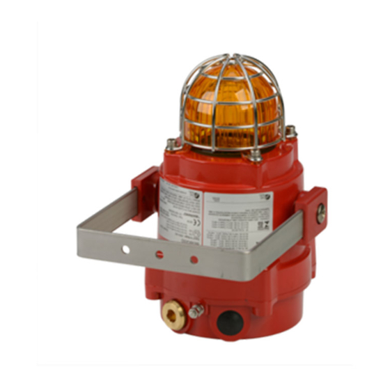
INSTRUCTION MANUAL (ATEX/IECEx/SIL2)
BExBG05D-P-SIL Flameproof Xenon SIL 2
Beacons For use in Flammable Gas and Dust
24V
II 2G
II 2D
0518
Issue B
16-06-17
Atmospheres
BExBG05D-P-SIL
The units can be installed in locations with the following
conditions:
Area Classification Gas:
Explosive gas air mixture likely to occur in
Zone 1
normal operation.
Explosive gas atmosphere not likely to
Zone 2
occur in normal operation but may be
present for short periods.
Gas Groupings:
Group IIA
Propane
Group IIB
Ethylene
Group IIC
Hydrogen and Acetylene
Temperature Classification:
T1
450ºC
T2
300ºC
T3
200ºC
T4
135ºC
100ºC (up to 45°C ambient)
T5
Area Classification Dust:
Explosive dust air mixture likely to occur in
Zone 21
normal operation.
Explosive dust air mixture not likely to
Zone 22
occur in normal operation, and if it does, it
will only exist for a short time.
Dust Groupings:
Group IIIA
Combustible Dusts
Group IIIB
Non-Conductive Dust
Group IIIC
Conductive Dust
Maximum Surface Temperature for Dust Applications:
IP Rating:
IP66/67 to EN/IEC60529 and IP6X to
EN/IEC60079-0, EN/IEC60079-31
Equipment Category:
Equipment Protection Level:
Ambient Temperature Range:
-50°C to +70°C Gas Groups IIA, IIB and IIC
-50°C to +70°C Dust Groups IIIA, IIIB and IIIC
SIL 2 Unit operating temperature range limits –25ºC to +60ºC
sales@e-2-s.com
www.e-2-s.com
Sheet 1 of 17
90ºC at +40 ºC ambient
105 ºC at +55 ºC ambient
120 ºC at +70 ºC ambient
2G / 2D
Gb / Db
Tel: +44 (0)208 743 8880
Fax: +44 (0)208 740 4200
(1)
Advertisement

Related Manuals for E2S BExBG05D-P-SIL


Summary of Contents for E2S BExBG05D-P-SIL
- Page 1 INSTRUCTION MANUAL (ATEX/IECEx/SIL2) BExBG05D-P-SIL Flameproof Xenon SIL 2 Beacons For use in Flammable Gas and Dust Atmospheres BExBG05D-P-SIL The units can be installed in locations with the following 1) Warnings conditions: • DO NOT OPEN WHEN AN EXPLOSIVE ATMOSPHERE IS PRESENT Area Classification Gas: •...
- Page 2 3) Type Approval Standards The beacon carries an EC Type Examination Certificate and IECEx Certificate of Conformity, and have been certified to comply with the following standards: EN60079-0:2012+A11:2013 / IEC60079-0:2011 (Ed 6): Explosive Atmospheres - Equipment. General requirements Fig. 1 Fixing Location for Beacon EN60079-1:2007 / IEC60079-1:2007 (Ed 6): Explosive Atmospheres - Equipment protection by flameproof 7) Access to the Flameproof Enclosure...
- Page 3 Terminal Nominal I/P Input Voltage Model No. Voltage Current Range BExBG05D-P-SIL 24Vdc 325mA 20-28V The input current will vary according to the voltage input level. The current levels shown above are for nominal input voltage. 2-off M20 9) Selection of Cable, Cable Glands, Cable Blanking Elements &...
- Page 4 When the signaling device is required to operate beacon the polarity is changed back to normal supply and the The new SIL 2 version of the E2S BExS110-SIL & BExS120- beacon will go into Active mode where it will start to SIL alarm horn sounder and BExBG05-P-SIL, BExBG10-P- function/flash.
- Page 5 Power relay RLY1-1 will be open whilst SIL 2 relay RLY1-2 Resetting Failure - It is possible that the SIL 2 unit can be will be closed contact between terminals 1 & 2. reset by hard resetting the unit using the reset jumper within If power is disrupted the SIL 2 unit will go into Fault mode, in the unit (see section 21) on hard resetting.
- Page 6 14) SIL 2 Wiring configuration and Beacon set-up - - + + Beacon Power Supply Terminals Flip / Flop Pin Header (Section 19) J2 Header – Shown in factory default position A (see section 14.3) removes power supply terminal J7 Header – Shown in block Fault resistor out of factory default position A circuit.
- Page 7 Multiple Unit Configuration When multiple units are used in the system, the following considerations are to be made by the customer: Customer panel capabilities - The customer is required to identify the minimum change in current the panel can detect (Panel resolution). This will therefore determine what resistors values to pick in section 3 below.
- Page 8 If the customer chooses to use this configuration within their system, it must be noted that the factory default settings for the unit does not have an EOL resistor installed. The customer can request E2S to install an EOL resistor and this will be depicted in the product code.
- Page 9 Multiple Unit Configuration When multiple units are used in the system, the following considerations are to be made by the customer: Customer panel capabilities - The customer is required to identify the minimum change in current the panel can detect (Panel resolution). This will therefore determine what resistors values to pick in section 3 below.
- Page 10 • 14-3 Header Pins Settings J1 Header Pin - Postion A, Factory default position J1 Header Pin - Postion B (pins 1 & 2 linked) (pins 1 & 2 not linked) places TB1 Current sense removes TB1 Current sense resistor out of circuit. resistor in circuit.
- Page 11 15) SIL Specific Unit Mounting 18) Flip-Flop Operation Requirements Two beacons can be mounted close to each other to form a flip-flop operation, where the beacons will flash alternately. The beacon should be mounted no closer that 2m from a To achieve this mode of operation, fit a pin header to the flip- beacon or light source of similar candela output.
- Page 12 21) Product Coding for Fault Resistor and Customer EOL Resistor The customer is able to identify the resistor values chosen on purchase from the product code. This is represented by the last two characters: BEXBG05D24DC-P-SIL-XX The first character denotes the value of the Fault resistor and the second character denotes the value of the EOL resistor.
- Page 13 M5 Plain Washer equipment. Guard The beacon cover is interchangeable, contact E2S Ltd for a replacement cover available in various colours. Cover To change the cover, unscrew the M5 socket head screws Fig. 13 Cover and Guard Fixtures and remove the M5 screws, M5 spring &...
- Page 14 Figure 14: Schematic of SIL 2 system wiring for fault detection in standby mode only – 4 wire installation configuration wired in series _______________________________________________________________________________________________________________________________ European Safety Systems Ltd. Impress House, Mansell Road, Acton, London W3 7QH sales@e-2-s.com Tel: +44 (0)208 743 8880 www.e-2-s.com Fax: +44 (0)208 740 4200 Document No.
- Page 15 Figure 15: Schematic of SIL 2 system wiring for fault detection in standby mode only – 4 wire installation configuration in Star formation _______________________________________________________________________________________________________________________________ European Safety Systems Ltd. Impress House, Mansell Road, Acton, London W3 7QH sales@e-2-s.com Tel: +44 (0)208 743 8880 www.e-2-s.com Fax: +44 (0)208 740 4200 Document No.
- Page 16 Figure 16: Schematic of SIL 2 system wiring for fault detection in standby mode only – 2 wire installation configuration wired in series _______________________________________________________________________________________________________________________________ European Safety Systems Ltd. Impress House, Mansell Road, Acton, London W3 7QH sales@e-2-s.com Tel: +44 (0)208 743 8880 www.e-2-s.com Fax: +44 (0)208 740 4200 Document No.
- Page 17 Figure 17: Schematic of SIL 2 system wiring for fault detection in standby mode only – 2 wire installation configuration in star formation _______________________________________________________________________________________________________________________________ European Safety Systems Ltd. Impress House, Mansell Road, Acton, London W3 7QH sales@e-2-s.com Tel: +44 (0)208 743 8880 www.e-2-s.com Fax: +44 (0)208 740 4200 Document No.
-
Page 18: Eu Declaration Of Conformity
This Declaration is issued under the sole responsibility of the manufacturer. Martin Streetz Document No.: DC-065_Issue_D Quality Assurance Manager Date and Place of Issue: London, 08/09/2016 E2S Telephone: +44 (0)20 8743 8880 Fax: +44 (0)20 8740 4200 Email: sales@e2s.com www.e2s.com DC-065_Issue_D (BExBG SIL2) - Page 1 of 1 - QAF_252_Issue_5...
Need help?
Do you have a question about the BExBG05D-P-SIL and is the answer not in the manual?
Questions and answers