Table of Contents
Advertisement
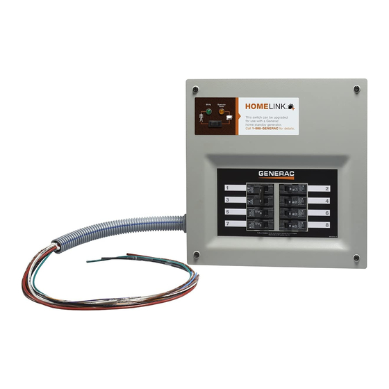
Models:
006852 Switch
006853 Switch, Cord and Resin Power Inlet Box
006854 Switch, Cord and Aluminum Power Inlet Box
006869 Manual to Automatic Upgrade Kit
Homelink Upgradeable Manual Transfer Switch
Para español , visita:
http://www.generac.com/service-support/product-support-lookup
Pour le français, visiter :
SAVE THIS MANUAL FOR FUTURE REFERENCE
Owner's Manual
MODEL NUMBER: _________________________
SERIAL NUMBER: _________________________
DATE PURCHASED:________________________
This product is not intended to be used in
a critical life support application. Failure to
adhere to this warning could result in
death or serious injury.
Register your Generac product at:
WWW.GENERAC.COM
http://www.generac.com/service-support/product-support-lookup
000961
WARNING
(000209a)
1-888-GENERAC
(888-436-3722)
Advertisement
Table of Contents

Related Manuals for Generac Power Systems 006852


Summary of Contents for Generac Power Systems 006852
- Page 1 Models: 006852 Switch 006853 Switch, Cord and Resin Power Inlet Box 006854 Switch, Cord and Aluminum Power Inlet Box 006869 Manual to Automatic Upgrade Kit Owner’s Manual Homelink Upgradeable Manual Transfer Switch 000961 MODEL NUMBER: _________________________ SERIAL NUMBER: _________________________ DATE PURCHASED:________________________...
- Page 2 WARNING California Proposition 65. Engine exhaust and some of its constituents are known to the state of California to cause cancer, birth defects, and other reproductive harm. (000004) WARNING California Proposition 65. This product contains or emits chemicals known to the state of California to cause cancer, birth defects, and other reproductive harm.
-
Page 3: Table Of Contents
Table of Contents Section 1: Introduction and Safety Section 4: Operation Introduction ..............1 Functional Tests ............9 Safety Rules ..............1 Manual Operation ............9 Transfer Mechanism Manual Operation ......9 Safety Symbols and Meanings ........2 Close to Generator Source Side .........9 Return to Utility Source Side ........10 Section 2: General Information Voltage Checks ............10 Unpacking ..............3... - Page 4 This page intentionally left blank. Homelink Upgradeable Manual Transfer Switch Owner’s Manual...
-
Page 5: Section 1: Introduction And Safety Introduction
Section 1: Introduction and Safety Introduction DANGER Thank you for purchasing a Generac Power Systems Inc. product. This unit has been designed to provide high- Indicates a hazardous situation which, if not avoided, will result in death or serious injury. -
Page 6: Safety Symbols And Meanings
Section 1: Introduction and Safety Safety Symbols and Meanings DANGER DANGER Electrocution. High voltage is present at Automatic start-up. Disconnect utility power and transfer switch and terminals. Contact with live render unit inoperable before working on unit. terminals will result in death or serious injury. Failure to do so will result in death or serious injury. -
Page 7: Section 2: General Information Unpacking
Section 2: General Information Section 2: General Information Unpacking Carefully unpack the transfer switch. Inspect closely for any damage that might have occurred during shipment. The purchaser must file with the carrier any claims for loss or damage incurred while in transit. Check that all packing material is completely removed from the switch prior to installation. -
Page 8: Safe Use Of Transfer Switch
Section 2: General Information The conductor size range is as follows: Wire Range Conductor Rating Tightening Temp. Torque Rating 1/0 - 14 50 in-lbs 167°F (75°C) (5.6 Nm) Safe Use of Transfer Switch WARNING Consult Manual. Read and understand manual completely before using product. -
Page 9: Section 3: Installation
Section 3: Installation Section 3: Installation Mounting the Transfer Switch DANGER Electrocution. Turn utility supply OFF before working on utility connections of the transfer switch. Failure to do so will result in death or serious injury. (000123) DANGER Equipment malfunction. Installing a dirty or damaged transfer switch will cause equipment malfunction and 000946 will result in death or serious injury. -
Page 10: Connecting Power Source And Load Lines
Section 3: Installation Connecting Front Panel Wiring Strip and insert incoming leads into terminals on power inlet. Insert white wire (neutral) into nickel Utilize the quick disconnect connector in the wiring plated screw terminal or white marking on the inlet. harness to remove the front panel during service or Carefully fold wires into the enclosure and reattach installation. -
Page 11: Installing Branch Circuit Conductors - Canadian Installations
Section 3: Installation Size all conductors, raceways, conduits, and The factory supplied breakers can be changed by the junction boxes, if required, to the applicable NEC installer. Install listed and labeled circuit breakers that are code articles and follow the NEC installation compatible with the transfer switch (See Breakers requirements for the wiring method(s) selected. - Page 12 Section 3: Installation Remove the lower left screw that secures the Terminate the neutral conductor from the generator divider plate in the transfer switch (B in Figure 3-4). power feeder onto the neutral terminal bar in the transfer switch (E in Figure 3-5).
-
Page 13: Section 4: Operation
Section 4: Operation Section 4: Operation Functional Tests CAUTION Following transfer switch installation and interconnection, Equipment damage. Do not use excessive force inspect the entire installation carefully. A competent, while manually operating the transfer switch. qualified electrician should inspect it. The installation Doing so could result in equipment damage. -
Page 14: Return To Utility Source Side
Section 4: Operation Return to Utility Source Side NOTE: Do NOT proceed until generator AC output volt- age and frequency are correct and within stated limits. Manually actuate switch to return manual operating handle to the DOWN position. Generator Tests Under Load Remove manual operating handle from movable contact carrier arm. -
Page 15: Checking Automatic Operation (Automatic Hsb Generator Only)
Section 4: Operation Press rocker button towards UTILITY direction (the nated prior to pressing the rocker button. The transfer transfer switch will not operate without utility switch will not transfer to generator mode if the Generator voltage present). The Utility Light is now off and in Light is not illuminated (this safeguards against acciden- normal operating condition (Utility voltage is tal transfer to the generator if generator power is not... -
Page 16: Shutting Generator Down While Under Load
Section 4: Operation Shutting Generator Down While NOTE: If turning the unit off for longer than 24 hours, remove the F1 fuse from the generator controller. Under Load To turn the generator ON: IMPORTANT NOTE: To turn the generator OFF Reinstall F1 fuse if necessary. -
Page 17: Section 5: Drawings And Diagrams
Section 5: Drawings and Diagrams Section 5: Drawings and Diagrams Installation Drawing No. 0K8843-A Homelink Upgradeable Manual Transfer Switch Owner’s Manual... -
Page 18: Interconnection Drawing No. 0K8845-A (Manual Transfer Connections)
Section 5: Drawings and Diagrams Interconnection Drawing No. 0K8845-A (Manual Transfer Connections) Homelink Upgradeable Manual Transfer Switch Owner’s Manual... -
Page 19: Interconnection Drawing No. 0K8844-C (Automatic Transfer Connections)
Section 5: Drawings and Diagrams Interconnection Drawing No. 0K8844-C (Automatic Transfer Connections) Homelink Upgradeable Manual Transfer Switch Owner’s Manual... - Page 20 Section 5: Drawings and Diagrams This page intentionally left blank. Homelink Upgradeable Manual Transfer Switch Owner’s Manual...
- Page 22 Part No. 0K9960 Rev. B 07/31/15 Printed in USA Generac Power Systems, Inc. ©2015 Generac Power Systems, Inc. All rights reserved S45 W29290 Hwy. 59 Specifications are subject to change without notice. Waukesha, WI 53189 No reproduction allowed in any form without prior written 1-888-GENERAC (1-888-436-3722) consent from Generac Power Systems, Inc.
Need help?
Do you have a question about the 006852 and is the answer not in the manual?
Questions and answers