
Related Manuals for Generac Power Systems RTS


Summary of Contents for Generac Power Systems RTS
- Page 1 RTS Automatic Transfer Switch TECHNICAL MANUAL A new standard of reliability This manual should remain with the unit.
- Page 2 Generac Power Systems, Inc., hereafter referred to as the “manu- Four commonly used safety symbols accompany the DANGER, WARNING and CAUTION blocks.
-
Page 3: Table Of Contents
Table of Contents Safety Rules ..........Inside Front Cover • Never handle any kind of electrical device while standing in water, while barefoot, or while hands or feet are wet. Section 1 — General Information ..........2 DANGEROUS ELECTRICAL SHOCK MAY RESULT. 1.1 Introduction ................ -
Page 4: Section 1 - General Information
Section 1 — General Information RTS “HS” Type Transfer Switch INTRODUCTION Figure 1.1 — Typical ATS Transfer Mechanism This manual has been prepared especially for the purpose of famil- iarizing personnel with the design, application, installation, opera- UTILITY LUGS tion and servicing of the applicable equipment. Read the manual carefully and comply with all instructions. -
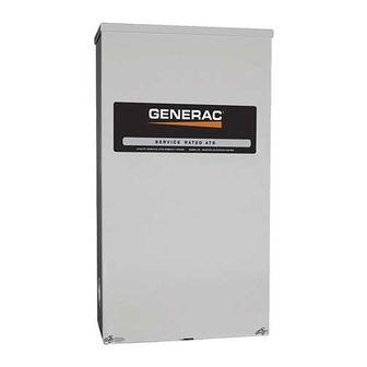
Page 5: Transfer Switch Enclosure
Section 2 — Installation RTS “HS” Type Transfer Switch MOUNTING Record the Model and Serial numbers in the space provided below for future reference. Mounting dimensions for the transfer switch enclosure are in this manual. Enclosures are typically wall-mounted. See “Installation MODEL # Diagram”. -
Page 6: Connecting Start Circuit Wires
Section 3 — Operation RTS “HS” Type Transfer Switch FUNCTIONAL TESTS AND Before connecting wiring cables to terminals, remove any surface oxides from the cable ends with a wire brush. If ALUMINUM con- ADJUSTMENTS ductors are used, apply corrosion inhibitor to conductors. Tighten terminal lugs to the torque values on "Utility Service Disconnect... -
Page 7: Close To Utility Source Side
Section 3 — Operation RTS “HS” Type Transfer Switch Figure 3.1 — Actuating Transfer Switch Attach handle to the moveable contact carrier arm. NOTE: Return handle to storage position in enclosure when finished with manual transfer. Move handle UP for the NORMAL (UTILITY) position. -
Page 8: Generator Tests Under Load
Section 3 — Operation RTS “HS” Type Transfer Switch GENERATOR TESTS UNDER Let the generator stabilize and warm up at no-load for at least five minutes. LOAD Set the generator's main circuit breaker (CB1) to its ON or Set the generator's main circuit breaker to its OFF or OPEN CLOSED position. -
Page 9: Section 4 - Notes
Section 4 — Notes RTS “HS” Type Transfer Switch... - Page 10 Section 4 — Notes RTS “HS” Type Transfer Switch...
- Page 11 Section 4 — Notes RTS “HS” Type Transfer Switch...
-
Page 12: Section 5 - Installation Diagram
Section 5 — Installation Diagram RTS “HS” Type Transfer Switch 100 & 200 Amp Non-Service Entrance ATS Enclosure - Drawing No. 0H2932-A... - Page 13 Section 5 — Installation Diagram RTS “HS” Type Transfer Switch 100 & 200 Amp Non-Service Entrance ATS Enclosure - Drawing No. 0H2932-A...
- Page 14 Section 5 — Installation Diagram RTS “HS” Type Transfer Switch 100 & 200 Amp Non-Service Entrance ATS Enclosure - Drawing No. 0G6832-A...
- Page 15 Section 5 — Installation Diagram RTS “HS” Type Transfer Switch 200 Amp Service Entrance ATS Enclosure - Drawing No. 0H4905-A...
-
Page 16: Section 6 - Electrical Data
Section 6 — Electrical Data RTS “HS” Type Transfer Switch Wiring Diagram/Schematic - Drawing No. 0H1488-B... - Page 17 Section 6 — Electrical Data RTS “HS” Type Transfer Switch Wiring Diagram/Schematic - Drawing No. 0H1488-B...
- Page 18 Section 6 — Electrical Data RTS “HS” Type Transfer Switch Transfer Switch Interconnections - Drawing No. 0H1894-A...
-
Page 19: Section 7 - Exploded Views & Parts Lists
Section 7 — Exploded Views and Parts List RTS “HS” Type Transfer Switch 200A Transfer Switch Assembly – Drawing No. 0H1710$-C Parts list on page 19. - Page 20 Section 7 — Exploded Views and Parts List RTS “HS” Type Transfer Switch 200A Transfer Switch Assembly – Drawing No. 0H1710$-C Parts list on page 19.
- Page 21 Section 7 — Exploded Views and Parts List RTS “HS” Type Transfer Switch 200A Transfer Switch Assembly – Drawing No. 0H1710$-C ITEM PART NO. QTY. DESCRIPTION ITEM PART NO. QTY. DESCRIPTION 0D9618 TRANSFER SW. HSB 200A 2P 250V 0C2262 DECAL, TERMINAL STRIP 074908 SCREW HHTT M5-0.8 X 10 BP...
- Page 22 Section 7 — Exploded Views and Parts List RTS “HS” Type Transfer Switch 100A Transfer Switch Assembly – Drawing No. 0G9659$-C...
- Page 23 Section 7 — Exploded Views and Parts List RTS “HS” Type Transfer Switch 100A Transfer Switch Assembly – Drawing No. 0G9659$-C ITEM PART NO. QTY. DESCRIPTION ITEM PART NO. QTY. DESCRIPTION 0C2237 TR SW-HSB 100A 2P 250V 067210A DECAL, GROUNDING LUG 074908 SCREW HHTT M5-0.8 X 10 BP...
-
Page 24: Section 8 - Warranty
GENERAC POWER SYSTEMS, INC. WARRANTY/SERVICE Generac Power Systems, Inc. will warrant that from the date of purchase, our transfer switch will be free from defects in material and workmanship for the items and periods set forth in the warranty statement found in the owners manual of the Generac Power Systems Inc.
Need help?
Do you have a question about the RTS and is the answer not in the manual?
Questions and answers