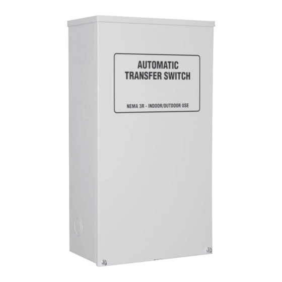
Summary of Contents for Generac Power Systems 004945-1
- Page 1 Automatic Transfer Switch Owner’s Manual ATS Service Entrance HS Type Transfer Switch Models: 005036-0, 100 Amp, 250 Volts and 004945-1, 200 Amp, 250 Volts This manual should remain with the unit.
-
Page 2: General Hazards
Generac Power Systems, Inc., hereafter referred to as Four commonly used safety symbols accompany the the “manufacturer”, cannot anticipate every possible... -
Page 3: Table Of Contents
Table of Contents Safety Rules .........Inside Front Cover • Competent, qualified personnel should install, operate and service this equipment. Adhere strictly Section 1 — General Information ........2 to local, state and national electrical and building 1.1 Introduction............. 2 codes. When using this equipment, comply with 1.2 Equipment Description ........... -
Page 4: Section 1 - General Information
Section 1 — General Information ATS “HS” Type Transfer Switch INTRODUCTION Figure 1.1 — Typical ATS Transfer Mechanism This manual has been prepared especially for the UTILITY LUGS purpose of familiarizing personnel with the design, application, installation, operation and servicing of the applicable equipment. -
Page 5: Transfer Switch Enclosure
Section 2 — Installation GTS “HS” Type Transfer Switch MOUNTING When requesting information or ordering parts for this equipment, make sure to include all information from Mounting dimensions for the transfer switch enclo- the DATA DECAL. sure are in this manual. Enclosures are typically wall-mounted. -
Page 6: Connecting Start Circuit Wires
Section 3 — Operation ATS “HS” Type Transfer Switch Conductor sizes must be adequate to handle the NOTE: maximum current to which they will be subjected to, When this ATS is used with an air-cooled genera- based on the 75°C column of tables, charts, etc. used tor, the LOAD 1 and LOAD 2 wires are not used. -
Page 7: Close To Normal Source Side
Section 3 — Operation ATS “HS” Type Transfer Switch Figure 3.1 — Actuating Transfer Switch Attach handle to the moveable contact carrier arm. NOTE: Return handle to storage position in enclosure when finished with manual transfer. Move handle UP for the NORMAL (UTILITY) position. -
Page 8: Voltage Checks
Section 3 — Operation ATS “HS” Type Transfer Switch VOLTAGE CHECKS NOTE: 1. Turn ON the UTILITY power supply to the trans- Do NOT proceed until generator AC output volt- fer switch using the service disconnect circuit age and frequency are correct and within stated breaker. -
Page 9: Section 4 - Installation Diagram
Section 4 — Installation Diagram ATS “HS” Type Transfer Switch Drawing No. 0F0016-B 271mm[10.67"] 26.5mm[1.04"] MOUNTING HOLES 0A6599tv 0A6599tv Ø6.3mm[Ø0.25"] 561mm[22.09" 597mm[23.50"] PADLOCK (CUSTOMER SUPPLIED) LOCATION 34mm[1.34"] 179.5mm[7.07"] KNOCKOUT SUITABLE FOR 3/4" & 1" CONDUIT SIZE KNOCKOUT SUITABLE FOR 1", 1-1/4", 1-1/2" CONDUIT SIZE KNOCKOUT SUITABLE 3 PLACES FOR 1", 1-1/4", 1-1/2"... -
Page 10: Section 5 - Electrical Data
Section 5 — Electrical Data ATS “HS” Type Transfer Switch Transfer Switch Interconnections - Drawing No. 0F0017-A... -
Page 11: Control Panel
Section 5 — Electrical Data ATS “HS” Type Transfer Switch Transfer Switch Interconnections - Drawing No. 0F0017-A IF ATS IS USED AS SERVICE ENTRANCE DEVICE A BONDING JUMPER WILL NEED TO BE INSTALLED SIZED TO MEET NATIONAL & LOCAL CODES. UTILITY METER SOCKET... - Page 12 Section 5 — Electrical Data ATS “HS” Type Transfer Switch Wiring Diagram/Schematic - Drawing No. 0F0015-A...
- Page 13 Section 5 — Electrical Data ATS “HS” Type Transfer Switch Wiring Diagram/Schematic - Drawing No. 0F0015-A...
-
Page 14: Section 6 - Exploded Views & Parts Lists
Section 6 — Exploded Views and Parts List ATS “HS” Type Transfer Switch 100A Transfer Switch Assembly – Drawing No. 0F0466$-D 63378-T 63378-T 63378-T 63378-T 0A2595 ORIENTATION WIRE NOTE WARNING VDC) WIRE VDC) WIRE 600V 30A, D2806-T (OPTIONAL) NEUTRAL VAC) (240 WIRE VAC) - Page 15 Section 6 — Exploded Views and Parts List ATS “HS” Type Transfer Switch 100A Transfer Switch Assembly – Drawing No. 0F0466$-D PART NO. QTY. DESCRIPTION 0C2237 TRANSFER SW-HSB 100A 2P 250V 0E7886H CB 0100A 2P 240V S BQ2 LB 0E7890 BRKT CB MTG BACK 0E9906 BRACKET, DISCONNECT SWITCH 100A...
- Page 16 Section 6 — Exploded Views and Parts List ATS “HS” Type Transfer Switch 200A Transfer Switch Assembly – Drawing No. 0E9801$-F INSIDE RIGHT SIDE NOTE:LOCATE HOLE IN BUSBAR UNDER BALL END OF SCREW 0C4449A-T TIGHTENING TORQUE 250 IN-LBS 0A6599tv 0A6599tv 0A6599tv 0A6599tv 0A6599tv...
- Page 17 Section 6 — Exploded Views and Parts List ATS “HS” Type Transfer Switch 200A Transfer Switch Assembly – Drawing No. 0E9801$-F ITEM PART NO. QTY. DESCRIPTION 0D9618 TRANSFER SW-HSB 200A 2P 250V 0E3628 CIRCUIT BREAKER 0200A 2P 120/240V S QN 0E3664 BASE QN CIRCUIT BREAKER 0E3553...
-
Page 18: Section 7 - Notes
Section 7 — Notes ATS “HS” Type Transfer Switch 16 Generac ® Power Systems, Inc. - Page 19 Section 7 — Notes ATS “HS” Type Transfer Switch Generac ® Power Systems, Inc. 17...
-
Page 20: Section 8 - Warranty
Generac Power Systems Inc. generator that this transfer switch will be utilized with.


Need help?
Do you have a question about the 004945-1 and is the answer not in the manual?
Questions and answers