Sign In
Upload
Manuals
Brands
Dionex Manuals
Laboratory Equipment
ICS-3000
Dionex ICS-3000 Manuals
Manuals and User Guides for Dionex ICS-3000. We have
1
Dionex ICS-3000 manual available for free PDF download: Operator's Manual
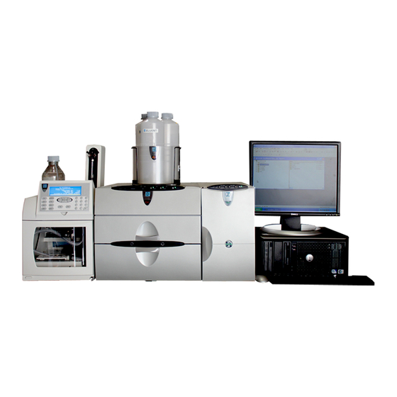
Dionex ICS-3000 Operator's Manual (392 pages)
Ion Chromatography System
Brand:
Dionex
| Category:
Laboratory Equipment
| Size: 14 MB
Table of Contents
Table of Contents
3
1 Introduction
17
ICS-3000 System Overview
17
ICS-3000 System Components
18
ICS-3000 System Control
25
ICS-3000 System Documentation
26
The ICS-3000 System Operator's Manual
27
Overview
27
Safety Messages and Notes
28
Safety and Regulatory Information
30
Safety Labels
30
2 Description
33
DP/SP Description
33
DP/SP Front Features
33
DP/SP Interior Components
35
Pump Heads
36
Pressure Transducer
36
Proportioning Valves (Gradient Pump Only)
36
Vacuum Degassing Module
37
Piston Seal Wash System
38
Static Mixer
38
DP/SP Flow Schematics
39
Isocratic Pump Flow Schematic
39
Gradient Pump Flow Schematic
40
DP/SP Rear Panel
41
Eluent Reservoirs
45
EO (Optional)
46
EG Description
47
EG Front Features
47
EG Interior Components
49
EG Rear Panel
53
EG Flow Schematic
55
DC Description
57
DC Front Features
57
DC Interior Components
60
DC Rear Panel
63
Injection Valves
66
Injection Valve Operation
66
Injection Valve Plumbing
68
CD Conductivity Detector
69
Heated Conductivity Cell
69
Suppressor
71
System Flow Schematic for Conductivity Detection
72
ED Electrochemical Detector
73
Amperometry Cell
73
Combination Ph-Ag/Agcl Reference Electrode
74
DC Amperometric Detection
76
Integrated and Pulsed Amperometric Detection
77
Cyclic Voltammetry Detection
79
Waveforms
79
Storing and Reprocessing Amperometry Data
84
Automation Manager
89
High-Pressure Switching Valves
90
Low-Pressure Valves
91
High- and Low-Pressure Valve Control
92
Reaction Coil Heater
94
I/O Option
95
I/O Option Connections
96
Analog Outputs
97
Power, Relay, and TTL Outputs
100
TTL Inputs
102
TC Description
107
TC Front Features
107
TC Interior Components
109
TC Rear Panel
111
Injection Valves
114
Injection Valve Operation
114
Injection Valve Plumbing
116
Column Identification (ID) System
117
Gas and Humidity Sensors
118
Theory of Operation
119
Predictive Performance
120
3 Configurations
121
Overview
121
4 Startup
129
Operating Precautions
129
EG Operating Precautions
129
ED Amperometry Cell Operating Precautions
131
System Startup Checklist
134
Preparing Samples
135
Collecting and Storing Samples
135
Pretreating Samples
135
Diluting Samples
136
Fill the Autosampler Vials and Load the Sample Tray
136
DP/SP Startup
139
Set up the Eluent Reservoirs
139
Set up the Piston Seal Wash System
140
Start the Pump
143
EG Startup
147
Setting the Eluent Concentration
147
DC Startup
151
Start the DC
151
Equilibrate the System and Verify Operational Readiness
152
TC Startup
153
Start the TC
153
Equilibrate the System and Verify Operational Readiness
154
5 Operation
155
Overview
155
Loading Samples with an Autosampler
156
Loading Samples with a Syringe
156
Loading Samples with a Syringe (Push Method)
157
Loading Samples with a Vacuum Syringe (Pull Method)
159
Example Commands for Loading and Injecting Samples
160
Commands for an as Autosampler
160
Commands for an AS40 Autosampler
160
Commands for a Remote Inject Device
161
Manual Sample Processing
162
Saving Manual Data
163
Automatic (Batch) Sample Processing
163
Creating a New Sequence
164
Starting Batch Sample Processing
165
6 Shutdown
167
DP/SP Shutdown
167
EG Shutdown
169
Short-Term Shutdown
169
Long-Term Shutdown
169
DC Shutdown
171
Consumables Storage
171
Amperometry Cell Storage
171
Short-Term Storage of the Amperometry Cell
171
Long-Term Storage of the Amperometry Cell
171
TC Shutdown
173
Consumables Storage
173
Short-Term Shutdown
173
Long-Term Shutdown
173
7 Maintenance
175
System Maintenance Checklists
175
Daily Maintenance
175
Weekly Maintenance
175
Periodic Maintenance
176
Annual Maintenance
176
DP/SP Routine Maintenance
177
DP/SP Daily Maintenance
177
DP/SP Weekly Maintenance
177
DP/SP Periodic Maintenance
178
DP/SP Annual Maintenance
178
EG Routine Maintenance
179
EG Daily Maintenance
179
EG Weekly Maintenance
179
EG Annual Maintenance
179
DC Routine Maintenance
181
DC Daily Maintenance
181
DC Weekly Maintenance
181
DC Periodic Maintenance
181
DC Annual Maintenance
182
TC Routine Maintenance
183
TC Daily Maintenance
183
TC Weekly Maintenance
183
TC Periodic Maintenance
184
TC Annual Maintenance
184
8 Troubleshooting
185
Audit Trail Error Messages
185
DP/SP Error Messages
186
EG Error Messages
187
DC Error Messages
188
TC Error Messages
189
Noisy Baseline
194
Poor Retention Time Reproducibility
197
Peak Retention Times Are too Early
199
Peak Retention Times Are too Late
199
No Peaks
199
Tailing Peaks
201
Low System Backpressure
201
High System Backpressure
202
Low Detector Output
202
High Background
203
DP/SP Troubleshooting
205
Troubleshooting DP/SP Error Messages
205
DP/SP Does Not Start
213
DP/SP Stops
214
DP/SP Liquid Leaks/Leak Alarm
215
Vacuum Degassing Module Low Vacuum
217
Vacuum Degassing Module Does Not Run
217
DP/SP Digital I/O Port Inoperative
217
EG Troubleshooting
219
Troubleshooting EG Error Messages
219
EG ALARM LED Is Lighted
223
EG POWER LED Fails to Light
224
Liquid Leaks in the EG
224
No Flow
225
EG Stops Operation
226
DC Troubleshooting
229
Troubleshooting DC Error Messages
229
Liquid Leaks from DC Components
237
VALVE Button Not Working
238
Amperometry Cell Troubleshooting
239
Amperometry Cell Ph Readout Always 7.0
239
Cannot Set Amperometry Cell Ph Readout to 7.0
240
Shift in Amperometry Cell Ph Readout
240
No Amperometry Cell Ph Readout or Intermittent Readout
241
Leak in Ph Reference Electrode Compartment
241
Shift in Ag/Agcl Reference Potential
242
TC Troubleshooting
243
Troubleshooting TC Error Messages
243
TC ALARM LED Is Lighted
269
Liquid Leaks from TC Components
269
TC Temperature Does Not Increase
270
TC Temperature Stabilizer Not Operating Properly
271
9 Service
273
DP/SP Service
273
Replacing Tubing and Fittings
273
Cleaning Eluent Reservoirs
274
Priming the DP/SP
275
Priming with the PUMP PRIME Button
275
Priming from the Control Panel
277
Replacing the Check Valves
278
Replacing a Piston Seal
281
Removing the Pump Head and Piston
281
Cleaning the Piston
284
Removing the Main Piston Seal
284
Removing the Piston Seal Wash Seal
285
Installing the Piston Seals
285
Reinstalling the Piston and Pump Head
286
Replacing the Piston
287
Removing the Pump Head and Piston
287
Installing the New Piston
289
Reinstalling the Pump Head
289
Replacing the Piston Seal Wash Tubing
290
Replacing the DP/SP Priming Valve Knob Seal
292
Changing the DP/SP Main Power Fuses
294
EG Service
297
Replacing Tubing and Fittings
297
Isolating a Restriction in the Liquid Lines
298
Replacing the Elugen Cartridge
298
EG Flow Schematic
299
Removing the Old Elugen Cartridge
300
Disposing of the Old Elugen Cartridge
302
Installing the New Elugen Cartridge
302
Conditioning the New Elugen Cartridge
304
Completing the Elugen Cartridge Installation
305
Replacing the CR-TC
306
Removing the Old CR-TC
306
Installing and Hydrating the New CR-TC
307
Completing the New CR-TC Plumbing
308
Replacing the RFIC Eluent Degasser
310
Installing a Backpressure Coil
311
Changing the EG Main Power Fuses
312
DC Service
313
Replacing Tubing and Fittings
313
Replacing the Leak Sensor
314
Rebuilding a High-Pressure (Injection) Valve
316
Replacing a High-Pressure (Injection) Valve Pod
318
Installing or Replacing an I/O Option Board
321
Changing the DC Main Power Fuses
323
CD Service Procedures
324
Calibrating the CD Cell
324
Replacing a Suppressor
325
Replacing a CD
327
Removing Trapped Air from the Conductivity Cell
328
ED Service Procedures
329
Disconnecting the Amperometry Cell
329
Replacing an Amperometry Cell Gasket
330
Polishing an Amperometry Cell Working Electrode
333
Replacing an Amperometry Cell Reference Electrode
336
Calibrating the Reference Electrode
338
Replacing the Reference Electrode O-Ring
340
Replacing an ED Detector
342
Replacing Tubing and Fittings
343
TC Service
343
Setting up the Column ID System
344
Rebuilding an Injection Valve
346
Replacing an Injection Valve Pod
347
Changing the Main Power Fuses
350
A • Specifications
351
DP/SP Specifications
351
Electrical
351
Environmental
351
Physical
351
Hydraulics
352
Computer Connections
353
I/O Interfaces and Inputs/Outputs
353
EG Specifications
355
Electrical
355
Environmental
355
Physical
355
Elugen Cartridge
356
DC Specifications
357
Electrical
357
Environmental
357
Physical
357
Lower Compartment Components
358
Temperature Control
358
Upper Compartment
358
Lower Compartment (Optional)
359
ICS-3000 Automation Manager
359
Reaction Coil Heater
359
Valves
359
ICS-3000 Conductivity Detector
360
ICS-3000 Electrochemical Detector
361
TC Specifications
363
Electrical
363
Environmental
363
Physical
363
Thermal Compartment
364
DP/SP Reordering Information
365
Advertisement
Advertisement
Related Products
Dionex ICS-90
Dionex ICS-2100
Dionex ICS-900
Dionex ICS-1000
Dionex ICS-1100
Dionex ICS-1600
Dionex AMMS ICE 300
Dionex ICS-6000
Dionex IonPac TCC Series
Dionex 043185
Dionex Categories
Laboratory Equipment
Analytical Instruments
Security Sensors
Measuring Instruments
Water Pump
More Dionex Manuals
Login
Sign In
OR
Sign in with Facebook
Sign in with Google
Upload manual
Upload from disk
Upload from URL