Table of Contents
Advertisement
RF180C communication module
SIMATIC Ident
RFID systems
RF180C communication module
Operating Instructions
12/2012
J31069-D0177-U001-A6-7618
___________________
Introduction
___________________
Description
___________________
Installation
___________________
Connecting
___________________
Parameterization
___________________
Maintenance and service
___________________
Diagnostics
___________________
Technical data
___________________
Dimension drawings
Connecting cable to the
___________________
reader
___________________
Ordering data
___________________
Service & Support
1
2
3
4
5
6
7
8
9
10
11
12
Advertisement
Table of Contents

Related Manuals for Siemens RF180C


Summary of Contents for Siemens RF180C
- Page 1 ___________________ RF180C communication module Introduction ___________________ Description ___________________ Installation SIMATIC Ident ___________________ Connecting RFID systems ___________________ RF180C communication module Parameterization ___________________ Maintenance and service Operating Instructions ___________________ Diagnostics ___________________ Technical data ___________________ Dimension drawings Connecting cable to the ___________________ reader...
- Page 2 Note the following: WARNING Siemens products may only be used for the applications described in the catalog and in the relevant technical documentation. If products and components from other manufacturers are used, these must be recommended or approved by Siemens. Proper transport, storage, installation, assembly, commissioning, operation and maintenance are required to ensure that the products operate safely and without any problems.
-
Page 3: Table Of Contents
Wiring connection block M12, 7/8"....................19 Wiring of the push-pull connection block ..................23 Loop-through connection of PROFINET IO and supply voltage..........26 Wiring an RF180C to a controller with RJ45 connector...............28 Connecting the RF180C to functional ground (PE) ..............28 Parameterization............................31 PROFINET IO configuration ......................31 Assigning device names to the I/O device...................32... - Page 4 Table of contents Connecting cable to the reader........................ 59 10.1 Routing of standard cables ......................59 10.2 Self-assembled cable........................62 Ordering data............................63 Service & Support............................ 65 RF180C communication module Operating Instructions, 12/2012, J31069-D0177-U001-A6-7618...
-
Page 5: Introduction
Introduction Purpose of these operating instructions The information provided in these Operating Instructions enables you to operate the RF180C communication module on a PROFINET IO controller. Basic knowledge required These operating instructions assume general knowledge of automation engineering and identification systems. - Page 6 ● Diagnostics information ● Display elements of the RF180C communication module ● Information on repair and maintenance (e.g. firmware update) ● Technical data as well as dimension drawings of the RF180C communication module ● Ordering data Recycling and disposal ● Due to its non-toxic equipment, the RF180C communication module can be recycled.
-
Page 7: Description
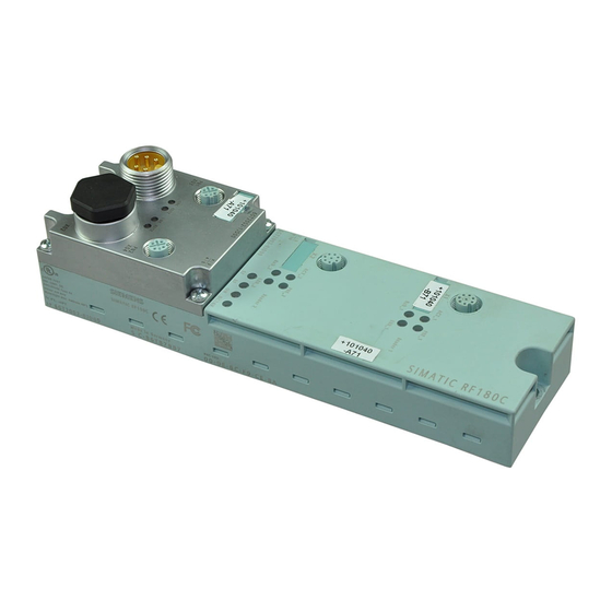
Description Area of application The RF180C communication module is a module that can be used on any controller for operating RFID components over PROFINET IO. RF180C communication module With M12 connection block (7/8") With push-pull connection block When operating the RF180C on a SIMATIC S7, a user-friendly function block is made available to the user (FB 45/FB 55). - Page 8 "Product Support (http://support.automation.siemens.com/WW/view/en/43532183)" page. Features Up to two readers can be operated on the RF180C at the same time. You can send a command to 2 readers simultaneously (FB 45/FB 55 or RFID standard profile when operating on a SIMATIC S7).
- Page 9 Description Design The RF180C has the same enclosure as the RFID communication module ASM 456 for PROFIBUS. For connecting to PROFINET IO, the RF180C communication module features a connection block in one of the following designs: ● M12 connection block design (7/8") ●...
- Page 10 Figure 2-2 Galvanic isolation of RF180C Integration The following figure shows how the RF180C with M12 connection block (7/8") is integrated in an automation system. The push-pull connection block is integrated in the same manner as the M12 connection block (7/8").
-
Page 11: Installation
The RF180C communication module is designed for easy assembly. Mounting position, mounting dimensions Mounting position There are no restrictions regarding the mounting position for the RF180C. Mounting dimensions and spacing Table 3- 1 Mounting dimensions of basic module with M12 connection block (7/8", without... -
Page 12: Mounting The I/O Module
Note Functional ground (PE) If a grounded metal mounting surface is used, the bottom mounting screw of the RF180C module already establishes a reliable grounding connection. This eliminates the need for a separate grounding cable. If you use the fixing screw as grounding connection, the thread of the fixing screw or the contact facing of the fastening nut on the base must be unpainted. -
Page 13: Mounting The Connection Block
(3 Nm tightening torque) at both fixing points (front, top and bottom). Figure 3-1 Mounting the I/O module Mounting the connection block Features The connection block connects the RF180C with the PROFINET IO and supplies the base unit with voltage. Requirements The base unit is already mounted RF180C communication module... - Page 14 (see Figure). Figure 3-2 Plug the M12 connection block (7/8'") onto the base unit and screw it on Figure 3-3 Plug the push-pull connection block onto the base unit and screw it on RF180C communication module Operating Instructions, 12/2012, J31069-D0177-U001-A6-7618...
-
Page 15: Replacing Labels
1. Push the screwdriver into the small opening of the label, and then lever it out. Figure 3-4 Removing labels 2. With your finger push the new label into the holder of the module. RF180C communication module Operating Instructions, 12/2012, J31069-D0177-U001-A6-7618... -
Page 16: Disassembling The Rf180C
Procedure The RF180C is wired up and operating. 1. Switch off the supply voltage for the RF180C. 2. Disconnect the wiring on the connection block. 3. Remove the 4 fixing screws from the connection block and pull the connection block off the base unit. -
Page 17: Connecting
When connecting non-specified devices to the RF180C, it is possible that the connected device may be destroyed. PROFINET IO connection system Detailed information about connecting the RF180C to PROFINET IO can be found in the "SIMATIC PROFINET system description (http://support.automation.siemens.com/WW/view/en/19292127/0/en)". - Page 18 Controller e.g. CPU S7-400 RF180C RF180C RF180C PROFINET 24 VDC Figure 4-1 RF180C with "BUS"setup Controller e.g. CPU S7-400 RF180C RF180C RF180C Switch (e.g. SCALANCE) PROFINET 24 VDC Figure 4-2 RF180C with "STAR" setup RF180C communication module Operating Instructions, 12/2012, J31069-D0177-U001-A6-7618...
-
Page 19: Wiring Connection Block M12, 7/8
4.1 Wiring connection block M12, 7/8" Reader connector system One reader always occupies one M12 socket on the RF180C. A pre-assembled cable therefore permits the optimum and easy connection of the reader. The connection cable is 2 m long in the standard version. - Page 20 Pin assignment for M12 connector, 4-pole, D coding (PROFINET IO) Assignment View of M12 connector, 4-pole, D coding (wiring side) Data line TxP Data line RxP Data line TxN Data line RxN Any connector can be used for infeed and looping through. RF180C communication module Operating Instructions, 12/2012, J31069-D0177-U001-A6-7618...
- Page 21 Ground for electronic / encoder supply (1M) Functional ground (PE) Electronics/encoder supply (1L+) (power supply for RF180C and reader) Load voltage supply (2L+) (unused on RF180C) Note When connecting up the supply voltage, we recommend the cable specified in the section "Ordering data (Page 63)"...
- Page 22 Always close all unused sockets using M12 or 7/8" sealing caps in order to ensure degree of protection IP65, IP66 or IP67. For order numbers, refer to the section "Ordering data (Page 63)". RF180C communication module Operating Instructions, 12/2012, J31069-D0177-U001-A6-7618...
-
Page 23: Wiring Of The Push-Pull Connection Block
– 5-core cable and push-pull cable connector for 1L+/2L+ – 4-core, shielded cable (bus cable) and push-pull cable connector for RJ-45 Note Refer to the manufacturer's documentation if you assemble the cables with the push-pull cable connectors. RF180C communication module Operating Instructions, 12/2012, J31069-D0177-U001-A6-7618... - Page 24 X01 DC 24 V for infeed X02 24 VDC for looping through Electronic/encoder supply 1L+ground Ground for electronic/encoder supply 2L+ load voltage supply Ground for load voltage supply 2M Functional ground (PE) RF180C communication module Operating Instructions, 12/2012, J31069-D0177-U001-A6-7618...
- Page 25 2L+ load voltage supply ④ X03 PN1 Push-pull socket for RJ-45 for feeding of PROFINET IO ③ X04 PN2 Push-pull socket for RJ-45 for looping through of PROFINET IO Figure 4-5 Connecting push-pull cable connectors RF180C communication module Operating Instructions, 12/2012, J31069-D0177-U001-A6-7618...
-
Page 26: Loop-Through Connection Of Profinet Io And Supply Voltage
If you disassemble the connection block during operation, only the power supply will be looped through. Data communication to subsequent devices will be interrupted from this module onwards. Figure 4-6 Loop-through connection of PROFINET IO and supply voltage RF180C communication module Operating Instructions, 12/2012, J31069-D0177-U001-A6-7618... - Page 27 Notes for wiring ● If you are wiring your structure, then you must take into account the impact of cable length on supply voltage to the RF180C. Example: When using a 10 m long cable with a diameter of 1.5 mm , the voltage drop is 2.5 V with...
-
Page 28: Wiring An Rf180C To A Controller With Rj45 Connector
Connecting the RF180C to functional ground (PE) Features You have to connect the RF180C to the functional ground (PE). For this purpose, a grounding screw for one grounding cable is provided on the communication module. If a grounded metal mounting surface is used, the bottom mounting screw of the RF180C module already establishes a reliable grounding connection. - Page 29 Connecting 4.5 Connecting the RF180C to functional ground (PE) Requirements ● Always make sure there is a low-resistance connection to the functional ground (PE). ● If you use the fixing screw as grounding connection, the thread of the fixing screw or the contact facing of the fastening nut on the base must be unpainted.
- Page 30 Connecting 4.5 Connecting the RF180C to functional ground (PE) RF180C communication module Operating Instructions, 12/2012, J31069-D0177-U001-A6-7618...
-
Page 31: Parameterization
Parameterization PROFINET IO configuration Introduction The GSDML file allows you to configure RF180C in STEP 7 V5.3 + SP 2 or higher or as of TIA Portal V11. The GSDML file must have been installed beforehand in the configuration software. -
Page 32: Assigning Device Names To The I/O Device
5.2 Assigning device names to the I/O device Follow the steps below to configure the RF180C on PROFINET IO with the TIA Portal: 1. Start the TIA Portal in the project view and call the menu command "Options > Install device description files". - Page 33 1. In project navigation, select the menu command "Online access > <your online access> > Update accessible devices". The available devices are displayed. 2. Select the required RF180C and click the entry "Online & Diagnostics" in the folder of the selected device. RF180C communication module...
- Page 34 4. Assign a device name and click the "Assign name" button. The device name must be unique within the system and must match the configuration. Result The device name is saved in connection block and base unit of the RF180C communication module. RF180C communication module...
- Page 35 1. In the Project tree, select the menu command "Online access > <your online access> > Update accessible devices". The available devices are displayed. 2. Select the required RF180C and click the entry "Online & Diagnostics" in the folder of the selected device. 3. Select the option "Functions > Assign name".
-
Page 36: Configuration Parameters Of The Rf180C
The GSDML file contains four parameters relevant to RFID that must be set. They are set by selecting the "Object properties" for slot 0 of the RF180C in HW Config. The parameters are described in the "Function Manual FB 45 (http://support.automation.siemens.com/WW/view/en/21738808)". -
Page 37: Input Parameters For Rf180C
B#16#00 ... FF RF200, RF300 reserved (00) MOBY D: B#16#00, 01 Special information on the input parameters for RF180C with FB45 in conjunction with the readers RF620R/RF630R can be found in the "Configuration manual RF620R/RF630R (http://support.automation.siemens.com/WW/view/en/33287195)". RF180C communication module Operating Instructions, 12/2012, J31069-D0177-U001-A6-7618... - Page 38 Input: BERO mode +16.0 field_ON_time BYTE B#16#0 Input: BERO time Special information on the input parameters for RF180C with FB55 in conjunction with the readers RF620R/RF630R can be found in the "Configuration manual RF620R/RF630R (http://support.automation.siemens.com/WW/view/en/33287195)". RF180C communication module Operating Instructions, 12/2012, J31069-D0177-U001-A6-7618...
- Page 39 Parameterization 5.4 Input parameters for RF180C Input parameters for RF180C with FB 101/116/132 (RFID standard profile) Figure 5-1 Input parameters for RF180C with FB 101/116/132 (RFID standard profile) RF180C communication module Operating Instructions, 12/2012, J31069-D0177-U001-A6-7618...
-
Page 40: Command Table Of The Rf180C
Parameterization 5.5 Command table of the RF180C Command table of the RF180C Table of commands of the RF180C for standard addressing (FB 45) Assignment is made in the UDT 20 by means of the "command" variable. Table 5- 4 Commands for RF180C with standard addressing... - Page 41 Parameterization 5.5 Command table of the RF180C RF180C command table with RFID standard profile (FB 101/116/132) Assignment is made in the UDT 1 by means of the "command" variable. Table 5- 6 RF180C commands with RFID standard profile Commands Command code...
- Page 42 Parameterization 5.5 Command table of the RF180C RF180C communication module Operating Instructions, 12/2012, J31069-D0177-U001-A6-7618...
-
Page 43: Maintenance And Service
RF180C communication module is included in the data communication by the PROFINET IO controller. Note If the connection block is replaced in addition to the base unit, the RF180C may not start up automatically. In this case, proceed as follows: RF180C communication module... - Page 44 In this case, check whether the bus configuration in the S7 CPU (created with HW Config) is consistent with the data saved in the RF180C. If necessary, correct the data in the RF180C. You will find further information in the sections "PROFINET IO configuration (Page 31)" and "Assigning device names to the I/O device (Page 32)".
-
Page 45: Firmware Update
In the case of a running application, both the update and command processing can be slower. Procedure Follow the steps below to run a firmware update on the RF180C with the SIMATIC Manager: 1. Start the SIMATIC Manager. 2. From the SIMATIC Manager select the menu command "PLC > Display Accessible Nodes". - Page 46 RF180C during which the new firmware is activated (active commands on the CM/ASM are canceled). – Otherwise, the RF180C remains in the previous status following the update. The new firmware is activated the next time the power is cycled. 7. Click the "Run" button to start the update.
- Page 47 2. In the Project tree, select the menu command "Online access > <your online access> > Update accessible devices". The available devices are displayed. 3. Select the required RF180C and click the entry "Online & Diagnostics" in the folder of the selected device. 4. Select the "Functions > Firmware update" option.
-
Page 48: Reset To Factory Settings
2. In the Project tree, select the menu command "Online access > <your online access> > Update accessible devices". The available devices are displayed. 3. Select the required RF180C and click the entry "Online & Diagnostics" in the folder of the selected device. 4. Select the "Functions > Reset to factory settings" option. -
Page 49: Diagnostics
Diagnostics Diagnosis using LEDs The following figure shows details of the LEDs of the RF180C. With M12 connection block (7/8") With push-pull connection block RF180C communication module Operating Instructions, 12/2012, J31069-D0177-U001-A6-7618... - Page 50 Meaning Lights up when the RF180C has completed start-up without errors. 24 VDC Lights up when the 24 V supply voltage is connected to the RF180C. ACT_1, ACT_2 The corresponding reader/SLG is active in processing a user command. ERR_1, ERR_2 * A flashing pattern indicates the last error to occur.
-
Page 51: Parameterization Of The Diagnostics
An alarm is generated when an event occurs as well as when the event ceases. Incoming alarm An event occurs and triggers an alarm. The SF LED of the S7 CPU is set as parameterized. RF180C communication module Operating Instructions, 12/2012, J31069-D0177-U001-A6-7618... -
Page 52: Structure Of The Diagnostic Data
The header of a diagnostic data record comprises 20 bytes of PROFINET IO-specific data. The manufacturer-specific diagnostic data start from Byte 21. For the RF180C, the diagnostic data are structured in accordance with the PROFIBUS Profile Guideline (PROFIBUS Proxy Guideline, Identification Systems Proxy Ident Function Block) for identification systems with MOBY-specific additional information. -
Page 53: Technical Data
FB 45 (normal addressing without multitag) / • FB 55 (normal addressing single tag and multitag) • RFID standard profile • Tag addressing Direct access via addresses Commands Initialize tag, read data from tag, write data to tag, etc. RF180C communication module Operating Instructions, 12/2012, J31069-D0177-U001-A6-7618... - Page 54 All mounting positions are possible Weight Basic device Approx. 210 g • • M12, 7/8" connection block Approx. 230 g • • Push-pull connection block Approx. 120 g • • Degree of protection IP67 RF180C communication module Operating Instructions, 12/2012, J31069-D0177-U001-A6-7618...
- Page 55 Connection block 1100 years • • Approvals cULus (file E116536) • FCC Code of Federal Regulations, • CFR 47, Part 15, Sections 15.107 and 15.109 (Class A) PI-certified according to Conformance Class B • RF180C communication module Operating Instructions, 12/2012, J31069-D0177-U001-A6-7618...
- Page 56 Technical data RF180C communication module Operating Instructions, 12/2012, J31069-D0177-U001-A6-7618...
-
Page 57: Dimension Drawings
Dimension drawings Dimension drawing for RF180C with fixing holes Dimension drawing of an RF180C with M12 bus connection block (7/8" PN) Figure 9-1 Dimension drawing of an RF180C with M12 bus connection block (7/8" PN) RF180C communication module Operating Instructions, 12/2012, J31069-D0177-U001-A6-7618... - Page 58 Dimension drawings 9.1 Dimension drawing for RF180C with fixing holes Dimension drawing of an RF180C with push-pull bus connection block Figure 9-2 Dimension drawing of an RF180C with push-pull bus connection block RF180C communication module Operating Instructions, 12/2012, J31069-D0177-U001-A6-7618...
-
Page 59: Connecting Cable To The Reader
● Extension cable for all RFID systems ● Length: 2 m, 5 m, 10 m, 20 m, 50 m Figure 10-3 Connecting cable M12 ↔ sub-D (MOBY D) ● Connecting cable MOBY D ● Length: 2 m RF180C communication module Operating Instructions, 12/2012, J31069-D0177-U001-A6-7618... - Page 60 10.1 Routing of standard cables Maximum cable length The RF180C can be operated with every reader configuration with the maximum cable length of 50 m. In some situations, longer connecting cables up to 1000 m are possible. The current consumption of the connected reader must however be taken into account. You will find further information in the relevant system manuals.
- Page 61 Table 10- 3 Connecting cable M12 ↔ sub-D 9-pin M12 connector (male) Sub-D connector (female) – – 1, 8 Note: Readers with D-sub connectors must be supplied with 24 VDC via an additional connector. RF180C communication module Operating Instructions, 12/2012, J31069-D0177-U001-A6-7618...
-
Page 62: Self-Assembled Cable
The pin assignment is listed in the following table. Table 10- 4 Pin assignment M12 connector (male) Signal Core color 1L+ (+ 24 V) Note data sheet provided by cable −RxD manufacturer −TxD Free Functional ground (PE)/shield RF180C communication module Operating Instructions, 12/2012, J31069-D0177-U001-A6-7618... -
Page 63: Ordering Data
Ordering data Table 11- 1 Ordering data - RF180C Ordering data Order number RF180C communications module 6GT2002-0JD00 max. 2 readers can be connected Connection block M12, 7/8" PN 6GT2002-1JD00 Push-pull connection block, RJ-45 6GT2002-2JD00 Labels 20 x 7 mm (1 x pack of 340) - Page 64 MOBY I / E / U / D; 50 m Reader cable for RF300; connector on the reader is angled; 6GT2891-0JH20 DVD "RFID Systems Software & Documentation" 6GT2080-2AA20 with FB 45 / FB 55, GSDML files, drivers, tools and RFID documentation RF180C communication module Operating Instructions, 12/2012, J31069-D0177-U001-A6-7618...
-
Page 65: Service & Support
Contacts If you have any further questions on the use of our products, please contact one of our representatives at your local Siemens office. The addresses are found on the following pages: ● On the Internet (http://www.siemens.com/automation/partner) ● In Catalog CA 01 ●... - Page 66 A guide to the technical documentation for the various products and systems is available on the Internet: SIMATIC Guide manuals (www.siemens.com/simatic-tech-doku-portal) Online catalog and ordering system The online catalog and the online ordering system can also be found on the Industry Mall Homepage (http://www.siemens.com/industrymall).
Need help?
Do you have a question about the RF180C and is the answer not in the manual?
Questions and answers