Table of Contents
Advertisement
Quick Links
SIMATIC
CN 4100
CN 4100 Communication System
Equipment Manual
6DL4170-1RB01-2XX0
6DL4178-0BH01-0XX0
6DL4172-4AX41-0XX0
6DL4172-5AX41-0XX0
02/2024
A5E50871363-AE
Cybersecurity information
Preface
System overview
Plant engineering
Installation
Connecting
Commissioning
Operation
Maintenance and servicing
Technical specifications
Dimension drawing
Data connections
Service & Support
1
2
3
4
5
6
7
8
9
10
A
B
C
Advertisement
Table of Contents

Related Manuals for Siemens 6DL4170-1RB01-2XX0


Summary of Contents for Siemens 6DL4170-1RB01-2XX0
- Page 1 Cybersecurity information Preface System overview SIMATIC Plant engineering CN 4100 CN 4100 Communication System Installation Connecting Equipment Manual Commissioning Operation Maintenance and servicing Technical specifications Dimension drawing Data connections Service & Support 6DL4170-1RB01-2XX0 6DL4178-0BH01-0XX0 6DL4172-4AX41-0XX0 6DL4172-5AX41-0XX0 02/2024 A5E50871363-AE...
- Page 2 Note the following: WARNING Siemens products may only be used for the applications described in the catalog and in the relevant technical documentation. If products and components from other manufacturers are used, these must be recommended or approved by Siemens. Proper transport, storage, installation, assembly, commissioning, operation and maintenance are required to ensure that the products operate safely and without any problems.
-
Page 3: Table Of Contents
Table of contents Cybersecurity information........................7 Preface ..............................9 System overview..........................11 Notes on the SIMATIC CN 4100 system ................11 SIMATIC CN 4100 ....................... 11 Basic components of the system..................12 3.3.1 Rack with 4 slots ........................ 12 3.3.2 CPU module........................ - Page 4 Table of contents Connecting ............................39 Notes on operation ......................39 Notes on wiring ......................... 40 Overview of rack wiring ..................... 42 Supply of the rack ......................43 6.4.1 Connections of the rack ..................... 43 6.4.2 Notes on internal wiring of the rack..................43 6.4.3 Supply voltage ........................
- Page 5 Table of contents 10.2.2 Technical specifications of the rack ..................68 10.2.3 Technical specifications - RS-232 serial module ..............70 10.2.4 Technical specifications - RS-485 serial module ..............72 Dimension drawing..........................75 Rack dimensions ........................ 75 Data connections ..........................77 Connections of the rack .....................
- Page 6 Table of contents CN 4100 Communication System Equipment Manual, 02/2024, A5E50871363-AE...
-
Page 7: Cybersecurity Information
Siemens’ products and solutions undergo continuous development to make them more secure. Siemens strongly recommends that product updates are applied as soon as they are available and that the latest product versions are used. Use of product versions that are no longer supported, and failure to apply the latest updates may increase customer’s exposure... - Page 8 Cybersecurity information CN 4100 Communication System Equipment Manual, 02/2024, A5E50871363-AE...
-
Page 9: Preface
The SIMATIC CN 4100 communication system may only be installed and operated by qualified personnel. Scope of this documentation This documentation applies to the following components of the SIMATIC CN 4100 communication system: Component Order number Rack 6DL4170-1RB01-2XX0 CPU module 6DL4178-0BH01-0XX0 RS232 serial communication module 6DL4172-4AX41-0XX0 RS-485 serial communication module 6DL4172-5AX41-0XX0 Note... - Page 10 • CNET Operating Manual (includes, for example, the commissioning of SIMATIC CN 4100): CNET (https://support.industry.siemens.com/cs/de/de/view/109820687) • Application example for SIMATIC CN 4100: FAQ (https://support.industry.siemens.com/cs/de/de/view/109801222) • PCS 7 library for SIMATIC CN 4100: PCS 7 (https://support.industry.siemens.com/cs/de/de/view/109801221) Conventions The following terms are used synonymously in this documentation: Term Synonyms...
-
Page 11: System Overview
System overview Notes on the SIMATIC CN 4100 system The SIMATIC CN 4100 communication system is a coherent I/O system consisting of the rack, at least one controller and optional communication modules. SIMATIC CN 4100 (Page 11) This section gives you an overview of the most important features and areas of application of the communication system. -
Page 12: Basic Components Of The System
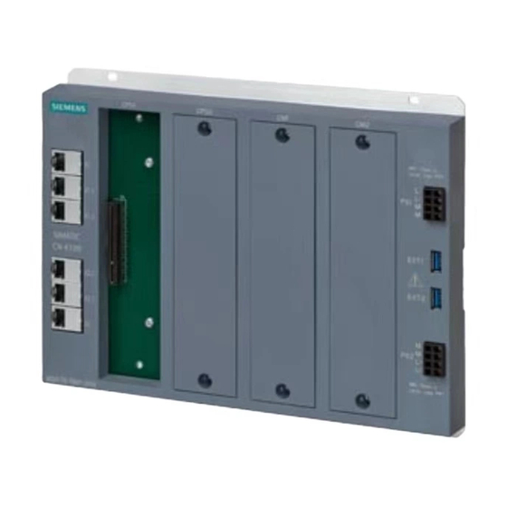
System overview 3.3 Basic components of the system ① Rack: Contains slots for the CPU modules and communications modules. Contains terminal points. Rack with 4 slots (Page 12) ② CPU modules: Can be installed individually or as a redundant pair. CPUs are plugged into the rack. CPU module (Page 14) ③... - Page 13 System overview 3.3 Basic components of the system Design of the front panel The following figure shows the front of the rack: ① RJ45 Ethernet port (with display LEDs) ② Slots for CPU modules ③ Slots for communications modules. Unused slots are equipped with a protective cover. ④...
-
Page 14: Cpu Module
System overview 3.3 Basic components of the system 3.3.2 CPU module Definition In the CN 4100 communication system, only the CN 4100 CPU is used as the central control module. Design of the front and bottom panel The following figure shows the front panel and bottom of the CPU module: ①... -
Page 15: Rs-232 Serial Communication Module
System overview 3.3 Basic components of the system Design of the side The following figure shows the left side of the CPU module: ① Fixing screw ② Nameplate (Page 26) 3.3.3 RS-232 serial communication module Definition The RS-232 serial communication module has the following features: •... - Page 16 System overview 3.3 Basic components of the system ① Fixing screw ② Status LED of the power supply ③ Ventilation slot ④ RS-232 connection: COM3 ⑤ RS-232 connection: COM4 ⑥ PE terminal ⑦ RS-232 connection: COM2 ⑧ RS-232 connection: COM1 Design of the left side The following figure shows the left side of the RS-232 serial communication module: CN 4100 Communication System Equipment Manual, 02/2024, A5E50871363-AE...
-
Page 17: Rs-485 Serial Communication Module
System overview 3.3 Basic components of the system ① Fixing screw ② Nameplate (Page 26) 3.3.4 RS-485 serial communication module Definition The RS-485 serial communication module has the following features: • The communication module is equipped with four RS-485 interfaces for up to 921.6 Kbps. •... - Page 18 System overview 3.3 Basic components of the system ⑦ RS-485 connection: COM2 ⑧ RS-485 connection: COM1 Design of the left side The following figure shows the left side of the RS-485 serial communication module: ① Fixing screw ② Nameplate (Page 26) CN 4100 Communication System Equipment Manual, 02/2024, A5E50871363-AE...
-
Page 19: Plant Engineering
Plant engineering Overview of plant engineering Topology Consider the position of CN 4100 in the topology. Notes on topology (Page 19) Configuration Consider the rules and options for configuring CN 4100. SIMATIC CN 4100 communication system configuration (Page 20) Protocols Consider the rules for using the communication protocols. Notes on communication via protocols (Page 23) Notes on topology The position of the SIMATIC CN 4100 communication system in the topology and typical... -
Page 20: Simatic Cn 4100 Communication System Configuration
Plant engineering 4.3 SIMATIC CN 4100 communication system configuration ES / OS Engineering System (ES) / Operating System (OS) User network Industrial Ethernet ES / OS NTP server Plant network Industrial Ethernet S7-410 SIMATIC CN 4100 S7-417 OPC UA Modbus TCP Third-party systems Note Network security... - Page 21 Plant engineering 4.3 SIMATIC CN 4100 communication system configuration Configuration rules The following configuration rules apply: • When a single CPU module is used, it must be plugged into the left CPU module slot. • When a single communication module is used, it must be plugged into the left slot for communication modules.
- Page 22 Plant engineering 4.3 SIMATIC CN 4100 communication system configuration ES / OS S7-410 H S7-410 H SIMATIC CN 4100 Configuration options The following schematic diagram shows the basis for the configuration options with the modules and integrated connections: SIMATIC CN 4100 X1.1 X1.2 X2.2...
-
Page 23: Notes On Communication Via Protocols
Plant engineering 4.4 Notes on communication via protocols Redun‐ Slots for CPU Slots for communi‐ Integrated connections dancy cations modules CPU 1 CPU 2 CM 1 CM 2 X1.1 X1.2 X2.1 X2.2 Non-re‐ dundant RS232 RS485 PN = Plant network TCP = Ethernet (for TCP/IP interface to third-party systems) Notes on communication via protocols Communication in the network is performed by protocols. -
Page 24: Protocols
Plant engineering 4.5 Protocols Protocols 4.5.1 PCS 7 protocols Definition PCS 7 protocols are communication protocols and are used in the plant network (SIMATIC environment). The following protocols are available for selection: • S7PutGet (Black Box) • TCON Only one of the protocols of this group can be used on CN 4100 at a time. 4.5.2 Protocols for third-party systems Definition... -
Page 25: Installation
• Keep the documentation included in the package in a safe place. It is required for initial commissioning and is part of the device. • Check the packaging and contents for visible transport damage. • Check the delivery for completeness. Inform your local Siemens contact in case of discrepancies or transport damage. CN 4100 Communication System... -
Page 26: Information On The Nameplate
Installation 5.3 Information on the nameplate Information on the nameplate Definition The nameplate is attached to the product by the manufacturer to classify and describe the product. Note Only the information printed on the nameplate of the respective component is valid. Approvals and certifications (Page 61) The approvals and certifications shown below are examples only. -
Page 27: Basics For Mounting
Installation 5.4 Basics for mounting ⑧ Instructions for disposal ⑨ Identification data The identification data are also provided as 2D code. 1P = Article No. (MLFB) 2P = Hardware and firmware version 1S = Serial number • First line = MAC address of the 1st Ethernet interface (ports X1 and X2) second line •... -
Page 28: Dimensions For The Drill Hole
Installation 5.4 Basics for mounting 5.4.2 Dimensions for the drill hole Definition The dimensions for the holes depend on the rack. The rack has four holes for fixing screws. Description All drill holes are equidistant from the edges. The following dimensions for the holes are available: CN 4100 Communication System Equipment Manual, 02/2024, A5E50871363-AE... -
Page 29: Notes On Protective Grounding
Installation 5.4 Basics for mounting 301 mm Outer dimensions of the rack 226 mm 38 mm Horizontal distance from the edge to the center of the hole 225 mm Horizontal distance between the centers of the holes 5 mm Vertical distance from the edge to the center of the hole 216 mm Vertical distance between the centers of the holes 5.4.3... -
Page 30: Grounding
Installation 5.4 Basics for mounting Grounding via reference potential The reference potential of the SIMATIC CN 4100 communication system can be connected to ground. A grounding screw is used for this. Notes on the reference potential (Page 31) Application (providing floating reference potential): •... -
Page 31: Notes On The Reference Potential
Installation 5.4 Basics for mounting 5.4.4.2 Notes on the reference potential If the SIMATIC CN 4100 communication system has been configured with grounded reference potential, any interference currents that occur are diverted to the protective conductor/local ground. A grounding screw contact is used for this. Note Grounding screw included in the scope of delivery The rack is equipped with grounded reference potential. -
Page 32: Overview Of The Installation
Installation 5.5 Overview of the installation When you connect the shielding to ground on only one side (i.e., at the beginning or end of the line), you limit attenuation to the lower frequencies. A one-sided shielding connection may be more suitable in the following cases: •... - Page 33 Installation 5.5 Overview of the installation CAUTION Restrictions on installation The following ambient temperatures are permissible: • Vertical installation: -30 °C to 60 °C • Horizontal installation: -30 °C to 45 °C Procedure The required sequence for installing the system is as follows: 1. Rack 2.
-
Page 34: Installation
Installation 5.6 Installation Applications • Removing the grounding screw (Page 34) • Installing a rack (Page 35) • Grounding the rack with a cable (Page 36) Plugging in the modules Plug modules into the slots of the rack. Start from the left with the CPU modules. If a slot is not equipped with a module, plug a slot cover onto the slot. -
Page 35: Installing A Rack
Installation 5.6 Installation ① Grounding screw in grounded state ② Metal enclosure of the rack (grounded) ③ Power supply connection ④ Ground potential of the internal circuit Result The reference potential of the rack is ungrounded. 5.6.2 Installing a rack Requirement •... -
Page 36: Grounding The Rack With A Cable
Installation 5.6 Installation Note Make the relevant settings on the rack before installing controllers with ungrounded reference potential. Result The rack is mounted and screwed to the base. 5.6.3 Grounding the rack with a cable Requirement • The basics for protective grounding are known. •... -
Page 37: Plugging In The Module
Installation 5.6 Installation ① Rack ② Contact washer ③ Fastening nut ④ Washer ⑤ Cable lug ⑥ Cable ⑦ Fixing bolt ⑧ Mounting level Result The rack is grounded via a cable. 5.6.4 Plugging in the module Requirement • The rack is mounted. •... -
Page 38: Grounding The Module With A Cable
Installation 5.6 Installation 5.6.5 Grounding the module with a cable Requirement • The basics for protective grounding are known. • The Module is mounted and screwed to the base. • The cable for grounding has a cross-section >=1.0 mm². • Required tools: –... -
Page 39: Connecting
Connecting Notes on operation Using the SIMATIC CN 4100 communication system in a plant requires that special rules and regulations be observed, depending on the area of application. This section provides an overview of the most important rules that you need to observe when using the SIMATIC CN 4100 communication system. -
Page 40: Notes On Wiring
Connecting 6.2 Notes on wiring • For supply voltage cables (24 V DC) and signals: If there is a risk of overvoltage, you need to provide lightning protection measures for internal lightning protection (e.g. lightning protection elements). • SIMATIC CN 4100 in LAN networks: In LAN networks (Local Area Networks), you may only operate the SIMATIC CN 4100 with RJ45 interfaces if the following condition is met: All connected nodes must be operated with SELV/PELV type voltage supplies (e.g. - Page 41 Connecting 6.2 Notes on wiring The terminal PS1 supplies the slots CPU1 and CM1. The terminal PS2 supplies the slots CPU2 and CM2. Note Requirements for safety extra-low voltage (SELV) The device may only be connected to a 24 V DC power supply that meets the requirements for safety extra-low voltage (SELV), EN / IEC / UL 61010-2-201 and DIN EN 61131-2.
-
Page 42: Overview Of Rack Wiring
Connecting 6.3 Overview of rack wiring ① Crimping TWIN end sleeves at the correct angle ② Cross-section of the terminal compartment • a: 1.8 mm • b: 2.4 mm ③ Spring release Mechanical and climatic environmental conditions (Page 61) Overview of rack wiring There are terminals for the supply voltage on the rack. Supply voltage (Page 47) Power supply Note the technical specifications and the information on the supply voltage. -
Page 43: Supply Of The Rack
Connecting 6.4 Supply of the rack Supply of the rack 6.4.1 Connections of the rack The rack has the following connections: ① RJ45 Ethernet port ② X1.1 ③ X1.2 ④ X2.2 ⑤ X2.1 ⑥ ⑦ Power supply connection ⑧ EXT2 USB 3.0 port ⑨... - Page 44 Connecting 6.4 Supply of the rack Ext1 USB 3.0 port Ext2 Internal wiring: Power supply The wiring is shown in the following figure: X1.1 EXT1 X1.2 EXT2 X2.2 X2.1 CN 4100 Communication System Equipment Manual, 02/2024, A5E50871363-AE...
- Page 45 Connecting 6.4 Supply of the rack Internal wiring: Bus connections The wiring is shown in the following figure: X1.1 EXT1 X1.2 EXT2 X2.2 X2.1 CN 4100 Communication System Equipment Manual, 02/2024, A5E50871363-AE...
- Page 46 Connecting 6.4 Supply of the rack Internal wiring: USB ports The wiring is shown in the following figure: X1.1 EXT1 X1.2 EXT2 X2.2 X2.1 USB 3.0 USB 2.0 CN 4100 Communication System Equipment Manual, 02/2024, A5E50871363-AE...
-
Page 47: Supply Voltage
Connecting 6.4 Supply of the rack Internal wiring: Ethernet ports The wiring is shown in the following figure: X1.1 EXT1 X1.2 EXT2 X2.2 X2.1 6.4.3 Supply voltage Definition The supply voltage is used to operate the SIMATIC CN 4100 communications system. Connect the supply voltage to the rack. -
Page 48: Step-By-Step Instructions
Connecting 6.4 Supply of the rack ③ Spring release ④ Push-in terminal 6.4.4 Step-by-step instructions 6.4.4.1 Connect the supply voltage to the rack Requirement • The supply voltage is switched off. • The respective conductor is connected. • Required tools: – Cable stripper Procedure 1. -
Page 49: Commissioning
Description of the commissioning Commissioning has to be done for all CPU modules. The following manuals describe the commissioning procedure: • CNET Operating Manual (https://support.industry.siemens.com/cs/de/de/view/109802239) Phases of commissioning Commissioning is divided into phases and can be tracked by the status display. -
Page 50: Phases
Commissioning 7.2 Phases Application (status of the LEDs): • Status of the LEDs during BIOS update (Page 50) • Status of the LEDs during firmware installation (Page 51) Configuration phase After a successful setup phase, the SIMATIC CN 4100 communication system is ready for configuration. -
Page 51: Status Of The Leds During Firmware Installation
Commissioning 7.2 Phases LEDs After 1s After 2s After 3s After 4s After 5s RL failure COMM failure BIOS update - LED status for error LEDs After 1s After 2s After 3s After 4s After 5s STOP Master ... -
Page 52: Status Of The Leds During System Configuration
Commissioning 7.2 Phases 7.2.3 Status of the LEDs during system configuration Note the LED status during configuration. The following tables show the lighting of the respective LED at the respective time (in seconds). LED status - CPU waiting for configuration LEDs After 1s After 2s After 3s... -
Page 53: Operation
Operation Operating the CPU module 8.1.1 Notes on the reset button Definition The reset button of the CPU module has the following functions: • Switching on: Switching on the CPU module (Page 54) • Restart: Restarting the CPU module (Page 54) • Switching off: Switching off the CPU module (Page 55) •... -
Page 54: Using The Reset Button
Operation 8.1 Operating the CPU module 8.1.2 Using the reset button 8.1.2.1 Switching on the CPU module Requirement • You have adhered to the basics for mounting. • The supply voltage is connected to the rack. • For power-on again: The CPU has been switched off before via the reset button. Procedure for commissioning after connection Switch on the supply voltage. -
Page 55: Switching Off The Cpu Module
Operation 8.1 Operating the CPU module 8.1.2.3 Switching off the CPU module Requirement • The supply voltage is connected to the rack. • The CPU module has been started. Procedure Press and hold the reset button for 6 seconds. Result The system shuts down together with the CPU module. 8.1.2.4 Resetting the CPU module Requirement... - Page 56 Operation 8.1 Operating the CPU module Meaning for redundant CPU modules The following table shows the status LEDs and their meaning. RTC = Runtime Container Master module Standby module Continuous light Flashes Continuous light Flashes Power supply Power supply OK Power supply OK ...
-
Page 57: Phases
Operation 8.2 Analyzing the communications modules 8.1.4 Phases 8.1.4.1 Status of the LEDs when using the Reset button Note the LED status when using the Reset button. The following tables show an illumination of the respective LED in sequence. The information is according to time in seconds. LED status - after the first actuation LEDs STOP... -
Page 58: Leds Of The Rj45 Port
Operation 8.3 LEDs of the RJ45 port Description The following table shows the possible states of the LED and their meaning. LED status Meaning Power supply error Continuous light Power supply OK LEDs of the RJ45 port Definition Each RJ45 port has two LEDs to indicate the status of its Ethernet connection. RJ45 Ethernet ports are available on the following devices: •... -
Page 59: Maintenance And Servicing
Maintenance and servicing Notes on maintenance When a SIMATIC CN 4100 communication system is configured redundantly, its modules may be replaced online. Applications • Replacing the module (Page 59) Maintenance 9.2.1 Replacing the module Requirement • The rack is mounted. • The protective grounding is mounted. •... - Page 60 Maintenance and servicing 9.2 Maintenance Result The module has been replaced. CN 4100 Communication System Equipment Manual, 02/2024, A5E50871363-AE...
-
Page 61: Technical Specifications
The SIMATIC CN 4100 system is tested according to IACS E10 (test specification for type approval). The SIMATIC CN 4100 system complies with RoHS (EN50581). Reference The certificates for the markings and approvals can be found on the Internet under Service&Support (https://support.industry.siemens.com/cs/). CN 4100 Communication System Equipment Manual, 02/2024, A5E50871363-AE... -
Page 62: Ce Marking
Technical specifications 10.1 Standards and approvals 10.1.2 CE marking Introduction The SIMATIC CN 4100 communication system meets the requirements and protection objectives of the following EC Directives and conforms to the harmonized European standards (EN) published for Programmable Logic Controllers in the Official Journals of the European Community: •... -
Page 63: Ukca Marking
• Interference emission measurement: 30 MHz - 1 GHz according to EN 55016-2-3:2010 (CISPR 16-2-3) 1-6 GHz according to EN 55016-2-3:2010 (CISPR 16-2-3) 10.1.3 UKCA marking Importer UK: Siemens plc Manchester M20 2UR 10.1.4 cULus approval Introduction The cULus approval applies to: • Rack •... - Page 64 Technical specifications 10.1 Standards and approvals Underwriters Laboratories Inc. meet the following standards: • UL 508 (Industrial Control Equipment) • CSA C22.2 No. 142 (Process Control Equipment) CN 4100 Communication System Equipment Manual, 02/2024, A5E50871363-AE...
-
Page 65: Technical Specifications Of Components
Technical specifications 10.2 Technical specifications of components 10.2 Technical specifications of components 10.2.1 Technical specifications - CPU module Technical specifications of CPU module Article number 6DL4178-0BH01-0XX0 General information Product type designation CPU modules 1 slot HW functional status FS03 Firmware version V3.0 Engineering with ... - Page 66 Technical specifications 10.2 Technical specifications of components Article number 6DL4178-0BH01-0XX0 Protocols Supports protocol for PROFINET IO EtherNet/IP Modbus TCP Modbus RTU Yes; with serial modules S7 protocol Yes; PUT/GET (PCS 7) or Tcon (PCSneo) OPC UA IEC 60870-5-102 IEC 60870-5-104 Yes;...
- Page 67 Technical specifications 10.2 Technical specifications of components Approvals Emission of radio frequency interference according Limit class A, for use in industrial environments to IEC61000-6-4, EN 55016 Received interference signals According to IEC 61000-6-5 Degree of protection and protection class Degree of protection according to DIN EN 60529 IP20 Ambient conditions, tested according to IEC 61131-2 Ambient temperature during operation, tested according to IEC 60068-2...
-
Page 68: Technical Specifications Of The Rack
Technical specifications 10.2 Technical specifications of components 10.2.2 Technical specifications of the rack Technical specifications of the rack Article number 6DL4170-1RB01-2XX0 General information Product type designation rack Engineering with V9.0 SP3 • PCS 7 configurable/integrated from version • PCS neo can be configured/integrated from V4.0... - Page 69 Technical specifications 10.2 Technical specifications of components Connections Interfaces USB ports • USB 2.0 • 1 port • USB 3.0 • 1 port Industrial Ethernet interfaces • 10/100/1000 Mbps • 1 port • 10/100/1000 Mbps switched • 2 ports CN 4100 Communication System Equipment Manual, 02/2024, A5E50871363-AE...
-
Page 70: Technical Specifications - Rs-232 Serial Module
Technical specifications 10.2 Technical specifications of components 10.2.3 Technical specifications - RS-232 serial module Technical specifications of extension module Serial RS-232 Article number 6DL4172-4AX41-0XX0 General information Product type designation serial RS232 expansion module Engineering with V9.0 SP3 • PCS 7 configurable/integrated from version •... - Page 71 Technical specifications 10.2 Technical specifications of components Article number 6DL4172-4AX41-0XX0 Weights Weight, approx. 0.42 kg CN 4100 Communication System Equipment Manual, 02/2024, A5E50871363-AE...
-
Page 72: Technical Specifications - Rs-485 Serial Module
Technical specifications 10.2 Technical specifications of components 10.2.4 Technical specifications - RS-485 serial module Technical specifications of extension module Serial RS-485 Article number 6DL4172-5AX41-0XX0 General information Product type designation serial RS485 expansion module Engineering with V9.0 SP3 • PCS 7 configurable/integrated from version •... - Page 73 Technical specifications 10.2 Technical specifications of components Article number 6DL4172-5AX41-0XX0 Weights Weight, approx. 0.42 kg CN 4100 Communication System Equipment Manual, 02/2024, A5E50871363-AE...
- Page 74 Technical specifications 10.2 Technical specifications of components CN 4100 Communication System Equipment Manual, 02/2024, A5E50871363-AE...
-
Page 75: Dimension Drawing
Dimension drawing Rack dimensions The following figures show the dimensions of the rack with four modules plugged in (two CPU modules and two different communication modules). Rack from front CN 4100 Communication System Equipment Manual, 02/2024, A5E50871363-AE... - Page 76 Dimension drawing A.1 Rack dimensions Rack from below CN 4100 Communication System Equipment Manual, 02/2024, A5E50871363-AE...
-
Page 77: Data Connections
Data connections Connections of the rack B.1.1 USB 3.0 ports of the rack Definition The USB 3.0 port is required for the setup and maintenance of the communication system. Description The rack is equipped with two USB 3.0 ports. Design Description USB_P5V_fused (O) USB_D0M (I/O) -
Page 78: Connections Of The Cpu Module
Data connections B.2 Connections of the CPU module Description The rack is equipped with the following Ethernet ports (10/100/1000 Mbps) for communication via fieldbus protocol or standard Ethernet: • Two Ethernet ports for the plant network • Four Ethernet ports for third-party systems Design Description BI_DA+... -
Page 79: Micro-Hdmi Port Of The Cpu Module
Data connections B.2 Connections of the CPU module Design Description TMDS Data2+ TMDS Data2 shield TMDS Data2− TMDS Data1+ TMDS Data1 shield TMDS Data1− TMDS Data0+ TMDS Data0 shield TMDS Data0− TMDS Clock+ TMDS Clock shield TMDS Clock− Reserved (HDMI 1.0-1.3c), Utility/HEC/ARC (Optional, HDMI 1.4+ with HDMI Ethernet channel and audio return channel) SCL (Line I²C "Serial Clock"... -
Page 80: Connections Of The Communication Modules
Data connections B.3 Connections of the communication modules Design Description USB_P5V_fused (O) USB_D0M (I/O) USB_D0P (I/O) Not connected USB_GND Connections of the communication modules B.3.1 RS-232 port of the RS-232 module Definition The RS-232 port is required as a serial interface for communication with external systems. Description The RS-232 communication module is equipped with four RS-232 ports. -
Page 81: Rs-485 Port Of The Rs-485 Module
Data connections B.3 Connections of the communication modules Description B.3.2 RS-485 port of the RS-485 module Definition The RS-485 port is required as a serial interface for communication with external systems. Description The RS-485 communication module is equipped with four RS-485 ports. Design Description Data-... - Page 82 Data connections B.3 Connections of the communication modules CN 4100 Communication System Equipment Manual, 02/2024, A5E50871363-AE...
-
Page 83: Service & Support
Service & Support Service & Support Attach / detach components The components are maintenance-free. Repairs to the components of the communication system itself may only be carried out by the manufacturer. Warranty The warranty is subject to compliance with the safety and commissioning instructions. CN 4100 Communication System Equipment Manual, 02/2024, A5E50871363-AE... - Page 84 Our Service & Support accompanies you worldwide in all matters related to Automation and Drives from Siemens. In more than 100 countries, directly on site and throughout all phases of the life cycle of your machines and plants.
- Page 85 Service & Support C.1 Service & Support Field service With Field Service, we offer services covering all aspects of commissioning and maintenance – so that the availability of your machines and systems is guaranteed in every situation. Spare parts Plants and systems in all industries worldwide must operate with more and more availability. We support you in preventing downtime from the outset: With a worldwide network and optimal logistics chains.
-
Page 86: Information And Support
• You can find information about the technical support available in the appendix of this documentation. • The technical documentation for the individual SIMATIC products and systems is available on the Internet (https://www.siemens.com/simatic-tech-doku-portal). • You can find the online catalog and online ordering system on the Internet (https:// mall.industry.siemens.com).
Need help?
Do you have a question about the 6DL4170-1RB01-2XX0 and is the answer not in the manual?
Questions and answers