
Related Manuals for LELY Hibiscus 455


Summary of Contents for LELY Hibiscus 455
- Page 1 LELY HIBISCUS Single-rotor rake 425 / 455 / 485 S Operator Manual 4.1059.8506.0 A English Original...
- Page 2 INTENTIONALLY BLANK...
- Page 3 Viseo, Voyager, Walkway and Welger are registered trademarks of the Lely Group. The right of exclusive use belongs to the companies of the Lely Group. All rights reserved. The information given in this publication is provided for information purposes only and does not constitute an offer for sale.
- Page 4 INTENTIONALLY BLANK TRADEMARKS, COPYRIGHT AND DISCLAIMER...
- Page 5 Intervention by technicians other than authorized Lely service • personnel or technicians who have Lely’s approval to perform certain tasks Modification done by the operator or third parties without Lely's • foreknowledge and/or authorization • Incidents such as vermin, freezing, ice, fire, lightning, flood, inundation or any other form of excessive water •...
- Page 6 INTENTIONALLY BLANK WARRANTY RESTRICTIONS...
- Page 7 LIST OF INCLUDED AMENDMENTS Issue Date Chapter(s) Remarks (yy/mm) 16/01 Full revision of the manual LIST OF INCLUDED AMENDMENTS...
- Page 8 INTENTIONALLY BLANK LIST OF INCLUDED AMENDMENTS...
- Page 9 Welcome to this Lely manual. This manual contains the technical information, operating instructions, maintenance procedures and troubleshooting information for the Lely Hibiscus 425 S, 455 S and 485 S. The information in this manual is for operators. Study and understand this information thoroughly before you operate the Lely Hibiscus.
- Page 10 The type and serial number plate of the rake is attached to the side of the main frame, behind the three-point hitch. Always include the type and serial number of your rake when you contact your local Lely service provider or when you order spare parts.
- Page 11 Left, Right, Rear and Front The positions left, right, rear and front in this manual refer to either: • The rake, as seen in the driving direction. • The particular component, as seen when standing in front of it. PREFACE...
- Page 12 INTENTIONALLY BLANK PREFACE...
-
Page 13: Table Of Contents
................1-1 The Lely Hibiscus 425 S, 455 S and 485 S ........... . . 1-1 Intended Use . - Page 14 Stop raking ................. . . 6-11 Take the Rake out of Operation .
-
Page 15: The Lely Hibiscus Rake
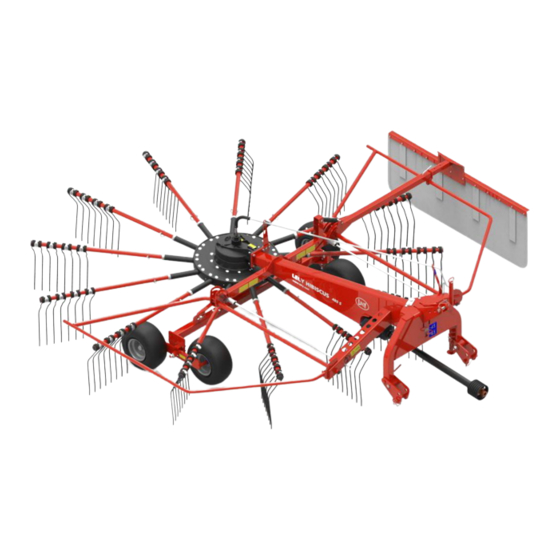
The Lely Hibiscus 425 S, 455 S and 485 S Only use the rake for its intended purpose! The Lely Hibiscus 425 S, 455 S and 485 S are mounted, single-rotor rakes for side delivery. The rake is equipped with 1 rotor with 11 or 13 tine arms, each equipped with 4 double tines. - Page 16 INTENTIONALLY BLANK The Lely Hibiscus Rake...
-
Page 17: Safety
SAFETY This chapter contains safety instructions you must obey when you use or do maintenance on your rake. It also explains the safety decals on the rake. Signal Icons Note the use of the signal words DANGER, WARNING and CAUTION with the safety messages. -
Page 18: Operating Safety
Before doing maintenance on the rake, always take the rake out of operation. • Use protective clothing, gloves, safety glasses and ear protectors if necessary. Only use genuine Lely parts. • • Clean or replace the safety decals regularly so that they can be read at all times. -
Page 19: Public Road Transport Safety
2.2.3 Public Road Transport Safety Before / when driving on public roads: Remove loose objects that may fall of the rake, such as stones or • pieces of clay. • Always keep a minimum distance of 3 m (10 ft) between the rake and electrical power lines. -
Page 20: Explanation Of The Safety Decals
2.2.5 Explanation of the Safety Decals Decal Explanation Danger: Flying objects Maintain a sufficient, safe distance from the rake while the tractor engine is running. Danger: Turning parts Keep away from all turning parts unless they are locked and cannot move. -
Page 21: Explanation Of Remaining Decals
Do not use mineral spirits, abrasive cleaners or other similar agents that may damage the safety decals. • Replace safety decals that are missing or that are illegible. Safety decals can be purchased from your local Lely service • provider. Safety... - Page 22 INTENTIONALLY BLANK Safety...
-
Page 23: Specifications
SPECIFICATIONS Hibiscus 425 S 455 S 485 S Working width 3.20 – 4.25 m (10.5 – 3.50 – 4.55 m (11.5 – 3.85 – 4.75 m (12.6 – 13.9 ft) 14.9 ft) 15.6 ft) Transport width 1.95 / 3.55 m (6.4 / 11.6 2.20 / 3.90 m (7.2 / 12.8 2.45 / 4.10 m (8.0 / 13.5 Transport height... - Page 24 INTENTIONALLY BLANK Specifications...
-
Page 25: Description
DESCRIPTION Lely Hibiscus S The Lely Hibiscus 425 S, 455 S and 485 S are mounted single-rotor rakes to rake grass, hay and straw. The rake has: A rotor • • Cam track Steering device • Working height adjustment system •... - Page 26 Figure 3. Main components KEY: 1. Safety guard - 2. Rotor - 3. Tine - 4. Rotor wheel - 5. Working height adjustment (winding handle) - 6. Parking jack - 7. PTO shaft Description...
-
Page 27: Tine Retainer (Optional)
Tine Retainer (optional) Figure 4. Tine arm with tine retainer KEY: 1. Tine retainer The tine arms of the rake can be equipped with tine retainers. This accessory makes sure that in the event of a collision with an obstacle, the tines will not fall off the tine arms due to broken coils. -
Page 28: Cam Track Lubrication (Optional)
Cam Track Lubrication (optional) Figure 5. Tine arm with grease nipple for cam track lubrication KEY: 1. Grease nipple The cam track in the rotor of the rake is lubricated with grease. The tine arm shaft equipped with a grease nipple simplifies and speeds up the cam track lubrication procedure. -
Page 29: Spare Wheel Support (Optional)
Spare Wheel Support (optional) Figure 6. Spare wheel support To enable a flat tyre to be mended quickly in the field, the rake can be fitted with a support for a spare wheel. Description... -
Page 30: Gauge Wheel (Optional)
Gauge Wheel (optional) Figure 7. Gauge wheel The gauge wheel improves the ability of the rake to follow ground contours. This may be required when raking in undulating fields. When the gauge wheel is used, the top link must be replaced by a chain. The rake can be lifted with the tractor three-point hitch as usual on headlands and for transport purposes. -
Page 31: Lighting Set (Optional)
Lighting Set (optional) Figure 8. Lighting set (455 S / 485 S) To be properly visible when driving on public roads a lighting set with warning signs can be installed on the Hibiscus 455 S and 485 S. Description... -
Page 32: Stabilization Kit (Optional)
Stabilization Kit (optional) Figure 9. Stabilization kit KEY: 1. Stabilization cylinder - 2. Bracket for tine arm storage The cylinder of the stabilization kit restrains the movement of the steering device. This is useful when raking in undulating fields. The stabilization kit has two brackets that must be installed on the rake for storage of the tine arms. -
Page 33: First Use
FIRST USE It is recommended to do the procedures in this chapter together with your authorized Lely dealer. Adjust the Length of the PTO Shaft To avoid damage to or reduction of the lifetime of the PTO shaft, the PTO shaft must not be extended over its maximum permissible length. -
Page 34: Adjust The Rake During First Use
Deburr and clean the safety guard tubes and the PTO shaft halves. Slide the two PTO shaft halves into each other. Slide the inner and outer safety guard tube over the PTO shaft. Connect the PTO shaft to the rake. Figure 10. -
Page 35: Operating Instructions
OPERATING INSTRUCTIONS Ensure no-one is near the rake at the moment the PTO is engaged. If anyone comes near the rake immediately stop the tractor and disengage the PTO. Switch off the tractor engine and remove the key before leaving the tractor cabin. - Page 36 Adjust the tractor’s three-point hitch arms to an equal height. Fit the lower arms of the three-point hitch to the linkage pins (4) (cat II) of the headstock (1) (see figure 12 on page 6-3). Attach the top link of the tractor to the headstock of the rake with a top link pin (2) (cat II).
-
Page 37: Put The Rake Into The Transport Position
Figure 12. Connect the rake to the tractor KEY: 1. Headstock - 2. Top link pin - 3. Parking jack - 4. Linkage pin (2x) - 5. PTO shaft Put the Rake into the Transport Position Make sure there are no persons in the area when you move the rake to the transport position. - Page 38 Put the rake into the transport position as follows: Take the rake out of operation (see page 6-12). Slide the swath curtain inwards and secure it with the locking pin. Pull the locking bar (2) (see figure 13 on page 6-4) and fold the safety guard (1) upwards.
- Page 39 Figure 14. Tine arms in the tine arm holders Operating Instructions...
-
Page 40: Put The Rake Into The Working Position
Figure 15. Secure the steering device with the locking pin KEY: 1. Locking pin Put the Rake into the Working Position Make sure that no-one is near the rake when it is moved from the transport position to the working position. Put the rake in the working position as follows: Pull out the locking pin, move it to the top position and release it to unlock the steering device. -
Page 41: Lift The Rake To Turn On Headlands
Slide the swath curtain outwards and secure it with the locking pin (see figure 24 on page 7-2). Lift the Rake to turn on Headlands Never drive the rake through the crop while the rotor is on the ground and is not rotating. This may damage the tines and the tine arms. If the rake is lifted in a turn, it will swing to the central position automatically. - Page 42 Create or move a Swath Figure 17. Move a swath Create a smaller Swath Create smaller (night) swaths by using only a part of the full working width of the rake. Figure 18. Create a smaller swath (half swath) Operating Instructions...
- Page 43 Create a fuller Swath If a fuller swath is required, double or multiple swaths can be created. Figure 19. Create a fuller swath (double swath) Figure 20. Create a fuller swath (multiple swath) Operating Instructions...
- Page 44 If Crop remains in the Middle behind the Rake If crop remains in the middle behind the rake, shorten the top link until the crop is picked up properly. Figure 21. Crop remains behind the rake If Crop remains on the Sides of the Rake If crop remains on the sides of the rake, extend the top link and adjust the working height or the cam track (see page 7-2).
-
Page 45: Start Raking
Start raking Make sure no people are near the rake at the moment the PTO is engaged. Keep safe distance from people. If a person comes near the rake, stop the tractor and disengage the PTO. Switch off the tractor engine and remove the key before leaving the tractor cabin. -
Page 46: Take The Rake Out Of Operation
Move the three-point hitch of the tractor upwards to lift the rake from the ground. Disengage the PTO. Wait for all moving parts to stop. When leaving the field: Put the rake into the transport position (see page 6-3). Take the Rake out of Operation To work safely it is important to take the rake out of operation before doing maintenance, troubleshooting, making adjustments or before certain operations. - Page 47 Figure 23. Disconnect the rake from the tractor KEY: 1. Parking jack - 2. Locking pin - 3. Hook Operating Instructions 6-13...
- Page 48 INTENTIONALLY BLANK 6-14 Operating Instructions...
-
Page 49: Adjustment
ADJUSTMENT Before you adjust the rake always: Stop the tractor. Engage the parking brake of the tractor. Disengage the PTO. Wait until all moving parts have stopped. Switch off the tractor engine and remove the key. Adjust the Swath Width The adjustment depends on the amount of crop and the working width. -
Page 50: Adjust The Working Height
Figure 24. Adjust the swath width KEY: 1. Swath curtain - 2. Locking pin Adjust the Working Height When raking straw, the wheel height must be adjusted higher. When the tines take up crop within the raking movement, the tines bend increasingly rearwards as there is more crop in front of them. - Page 51 Adjust the rotor height slightly lower at the side of the swath curtain with the height adjustment system of the rotor wheels (see figure 26 on page 7-4). Turn the winding handle (1) (see figure 27 on page 7-5) to the middle of the height adjustment range.
- Page 52 Figure 26. Example: adjust the rotor wheels at the swath curtain side slightly lower KEY: 1. Height position of the right rotor wheels - 2. Left rotor wheels (swath curtain side) positioned one position higher than the right rotor wheels Adjustment...
-
Page 53: Adjust The Cam Track
Figure 27. Adjust the working height with the winding handle KEY: 1. Winding handle for fine working height adjustment Adjust the Cam track The position of the cam track determines when the tine arms release the crop. Adjustment of the cam track to earlier or later crop release has an effect on the shape and width of the swath. - Page 54 Figure 28. Adjust the cam track KEY: 1. Cam track adjustment strip - 2. Lynch pin Adjustment...
- Page 55 Figure 29. Earlier / later release of the crop KEY: A: Turning direction of the rotor Adjustment...
- Page 56 INTENTIONALLY BLANK Adjustment...
-
Page 57: Maintenance
MAINTENANCE Preventive Maintenance Schedule Before you do maintenance on the rake always: Stop the tractor. Engage the parking brake of the tractor. Disengage the PTO. Wait until all moving parts have stopped. Switch off the tractor engine and remove the key. Correct servicing of the rake is vital for ensuring reliable and safe operation. -
Page 58: Preventive Maintenance Procedures
Lubricate the lower rotor wheel assembly (see page 8- Lubricate the gearbox of the rotor (see page 8-4). Make sure the PTO shaft telescopes smoothly. Make sure the rake is not damaged. Repair or replace damaged parts. Make sure the tyre pressure of the rotor wheels is correct (see page 8-16). -
Page 59: Lubricate The Bearing Block Of The Pto Extension
Figure 30. Grease points of the primary PTO shaft KEY: A: Grease nipple of the universal joint B: Grease nipple of the guard bearing C: Profiled tube D: Grease nipple of the clutch 8.2.2 Lubricate the Bearing Block of the PTO Extension Requirements •... -
Page 60: Lubricate The Gearbox Of The Rotor
Figure 31. Lubricate the bearing block of the PTO extension KEY: 1. Grease nipple of the PTO extension 8.2.3 Lubricate the Gearbox of the Rotor Requirements • Grease pump • Biodegradable grease (SEP2) Procedure Take the rake out of operation (see page 6-12). Lubricate the grease nipple of the rotor gears (1) with the grease pump. -
Page 61: Lubricate The Lower Rotor Wheel Assembly
KEY: 1. Grease nipple of the gears - 2. Grease nipple of the bearing of the axis 8.2.4 Lubricate the Lower Rotor Wheel Assembly Requirements Grease pump • • Biodegradable grease (SEP2) Procedure Take the rake out of operation (see page 6-12). Lubricate the two grease nipples on the lower rotor wheel assembly. -
Page 62: Lubricate The Height Adjustment Winding Handle
Figure 32. Lubricate the lower rotor wheel assembly KEY: 1. Grease nipple of the splines - 2. Grease nipple of the lower rotor wheel assembly pivot point (2x) 8.2.5 Lubricate the Height adjustment Winding Handle Requirements • Grease pump Biodegradable grease (SEP2) •... -
Page 63: Lubricate The Steering Device Of The Headstock
Figure 33. Lubricate the height adjustment winding handle KEY: 1. Grease nipple of the height adjustment winding handle 8.2.6 Lubricate the Steering Device of the Headstock Requirements Grease pump Biodegradable grease (SEP2) Procedure Take the rake out of operation (see page 6-12). Lubricate the grease nipples of the steering device. -
Page 64: Lubricate The Cam Track (Standard Tine Arms)
Figure 34. Lubricate the steering device KEY: 1. Grease nipple of the steering device: up / down (behind the plate) - 2. Grease nipple of the steering device: left / right 8.2.7 Lubricate the Cam Track (Standard Tine Arms) When lubricating the cam track turn the rotor manually to spread the grease over the entire cam track. -
Page 65: Lubricate The Cam Track (Grease Nipple On Tine Arm)
While you lubricate the cam track, manually turn the rotor 90 the same direction as during normal operation. Walk with the turning rotor to keep the grease pump close to the cam track. Repeat the steps 4 and 5 until the entire cam track is lubricated. Figure 35. -
Page 66: Lubricate The Tine Arms
KEY: 1. Cam track - 2. Grease nipple for cam track lubrication 8.2.9 Lubricate the Tine Arms Requirements Grease pump • • Biodegradable grease (SEP2) Procedure Take the rake out of operation (see page 6-12). Remove the screw of the cover plate (1) (see figure 36 on page 8- 11). -
Page 67: Torque Tighten The Nuts Of The Tine Arm Carriage Bolts (425 S / 455 S)
Figure 36. Lubricate the tine arm KEY: 1. Screw - 2. Grease nipple - 3. Cover plate 8.2.10 Torque tighten the Nuts of the Tine Arm carriage Bolts (425 S / 455 S) Requirements • Torque wrench Procedure Take the rake out of operation (see page 6-12). Torque tighten the inner ring of nuts (A) (see figure 38 on page 8- 13) to 110 Nm in the order as shown in the picture. - Page 68 Skip the next three pairs of nuts (in this example the pair of nuts with numbers 2,3, and 4). Then tighten the next pair of nuts (in this example the pair of nuts with number 5). Repeat this until all 22 nuts are torque tightened (so the tightening order is 1, 5, 9, 2, 6, 10, 3, 7, 11, 4, 8) Figure 37.
- Page 69 Figure 38. Torque tighten the nuts of the tine arm carriage bolts (425 S / 455 S) KEY: A: Inner ring of nuts. Tightening order 1, 5, 9, 2, 6, 10, 3, 7, 11, 4, 8 B: Outer ring of nuts. Tightening order 1, 5, 9, 2, 6, 10, 3, 7, 11, 4, 8 Maintenance 8-13...
-
Page 70: Torque Tighten The Nuts Of The Tine Arm Carriage Bolts (485 S)
8.2.11 Torque tighten the Nuts of the Tine Arm carriage Bolts (485 S) Requirements Torque wrench • Procedure Take the rake out of operation (see page 6-12). Torque tighten the inner ring of nuts (A) (see figure 39 on page 8- 15) to 110 Nm in the order as shown in the picture. - Page 71 Figure 39. Torque tighten the nuts of the tine arm carriage bolts (485 S) KEY: A: Inner ring of nuts. Tightening order 1, 6, 11, 3, 8, 13, 5, 10, 2, 7, 12, 4, 9 B: Outer ring of nuts. Tightening order 1, 6, 11, 3, 8, 13, 5, 10, 2, 7, 12, 4, 9 Maintenance 8-15...
-
Page 72: Make Sure The Tyres Have The Correct Pressure
8.2.12 Make sure the Tyres have the correct Pressure Make sure the rake is out of operation when you inflate the tyres. Do not over-inflate the tyres. Make sure the tyres of the rotor wheels have a pressure of 2.75 bar (40 Psi). -
Page 73: Replace The Tine Arm(S)
Figure 40. Replace the tine(s) KEY: 1. Bolt - 2. Clamp block - 3. Cap - 4. Tine - 5. Nut 8.3.2 Replace the Tine Arm(s) Requirements • Torque wrench • Loctite 243 • Grease pump Procedure Take the rake out of operation (see page 6-12). Remove the lynch pin from the lock pin (6) (see figure 41 on page 8-18). - Page 74 Loosen the nuts on the carriage bolts of the adjacent tine arms. Remove the tine arm shaft from the rotor. Install the tine arm shaft into the cam track. Make sure the bearing roller at the outer end of the tine arm is properly positioned into the cam track (see figure 42 on page 8-19).
-
Page 75: Replace A Rotor Wheel
Figure 42. Position of the tine arm bearing roller in the cam track KEY: 1. Cam track - 2. Tine arm - 3. Tine arm bearing roller 8.3.3 Replace a Rotor Wheel Lift the rake from the ground when you do this procedure. Requirements Torque wrench •... - Page 76 Placing a support underneath the rotor to prevent it from • falling down. • If necessary other measures to secure the rake against unexpected movement. Remove the cap (6) (see figure 43 on page 8-20) of the rotor wheel. Remove the nut (5) that secures the rotor wheel. Remove the washer (4).
- Page 77 Figure 44. Position of the sealing ring and the washer Maintenance 8-21...
- Page 78 INTENTIONALLY BLANK 8-22 Maintenance...
-
Page 79: Troubleshooting
TROUBLESHOOTING Symptom Action The crop is scattered behind the rake. • Reduce the PTO speed. The overload clutch of the PTO shaft engages. Reduce the driving speed. • • When raking excessive crop volume: do not use the full width capacity of the rake. The working width or shape of the swath is not •... - Page 80 INTENTIONALLY BLANK Troubleshooting...
-
Page 81: 10 Disposal
Read the safety data sheets of the used lubricants and fluids for correct disposal. All lubricants and fluids must be disposed in compliance with the local rules and regulations. Contact your local authority or local Lely service provider for further details. Disposal... - Page 82 INTENTIONALLY BLANK 10-2 Disposal...
- Page 83 Index Cam track ...... 4-1, 7-5, 8-1, 8-8–8-9, 8-19 Raking ........6-7, 6-11–6-12, 8-1 Recycle............10-1 Carriage bolts ........8-11, 8-14 Rotor ..............4-1 Clean ............8-1, 8-16 Corrective maintenance ........8-16 Crop ..............9-1 Safety ...............2-1 Safety decals ........2-3–2-5, 8-1 Decals ...............2-4 Safety guard ..........
- Page 84 INTENTIONALLY BLANK Index...
Need help?
Do you have a question about the Hibiscus 455 and is the answer not in the manual?
Questions and answers