Table of Contents
Advertisement
Quick Links
Advertisement
Table of Contents

Subscribe to Our Youtube Channel
Related Manuals for LELY POLYMAT 300W


Summary of Contents for LELY POLYMAT 300W
- Page 1 O P E R A T O R ' S M A N U A L POLYMAT W 300 / 400 H-HV.004. 0698...
-
Page 3: Table Of Contents
TABLE OF CONTENTS ....................page PREFACE ..........................36 WARRANTY CONDITIONS .....................36 TYPE- AND SERIAL NUMBER OF YOUR MACHINE ..........36 SAFETY INSTRUCTIONS ....................37 EXPLANATION OF SAFETY DECALS ON THE MACHINE ........38 1 INTRODUCTION ......................39 2 ADJUSTMENT FOR OPERATION ................40 3 MOUNTING THE POLYMAT ..................41 Mounting behind a LELYTERRA ..............41 Mounting behind the tractor................42 4 TRANSPORT .......................43... -
Page 4: Preface
PREFACE This Operator’s Manual is meant for personnel that are operating the machine and are responsible for its daily maintenance. Kindly read this manual fully prior to starting work. Such instructions as are related to your safety and/or that of others are marked in the margin by a warning triangle with exclamation mark. -
Page 5: Safety Instructions
- Observe the prevailing legislation for public road transport. - Use flashing lights or other safety signs, when required. - Don’t stand on the machine. - Use genuine Lely parts only. - Remove the pressure from hydraulic systems before starting work on them and/or before coupling/uncoupling hydraulic hoses. -
Page 6: Explanation Of Safety Decals On The Machine
EXPLANATION OF SAFETY DECALS ON THE MACHINE • Carefully read operator’s manual before handling the machine. Observe instructions and safety rules when operating. • Never exceed the maximum PTO speed which is obligatort for the machine. • Adjust the ball valve of the marker control to the closed (TRANSPORT) position if the machine needs to be transported. -
Page 7: Introduction
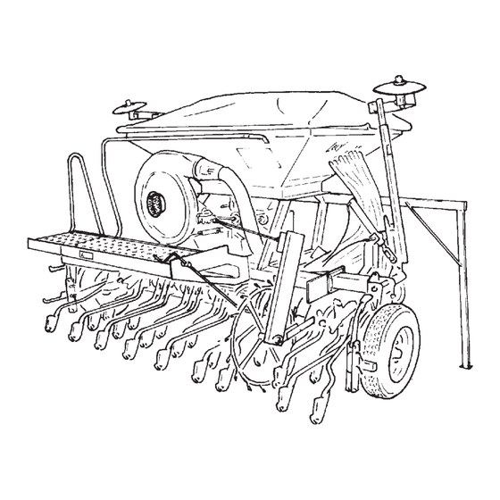
1 INTRODUCTION The POLYMAT W is a pneumatic drill capable of applying most seeds with diameters ranging from 1 to 10 mm. The PTO-driven fan A (fig. 1) causes a flow of air which transports the seeds towards the coulters E. The metering device B at the bottom of the elevation column C ensures that the seeds are taken up by the air flow. -
Page 8: Adjustment For Operation
2 ADJUSTMENT FOR OPERATION The POLYMAT W can be coupled behind a LELYTERRA or directly behind a tractor. The LELYTERRA needs to be fitted with the correct linkage parts. See supplement C for the assembly and adjustment of the linkage kit. For individual operations of the POLYMAT, a special solo hitch has to be fitted (see supplement C). -
Page 9: Mounting The Polymat
- Lower the LELYTERRA until the POLYMAT is in a horizontal position (fig. 7). - Mount the top link in the lowermost hole of the LELY- TERRA headstock by means of a top link pin. - Check if the ball valve (fig. 8) is closed (TRANSPORT position). -
Page 10: Mounting Behind The Tractor
- Adjust the chain lenght. If the chains are shortened or the adjustment strips A (fig. 9) are secured higher up, the POLYMAT will follow the LELYTERRA sooner when the combination is lifted. The tractor’s hydraulic lift can then be adjusted lower. Throughout the operation, the chains are not allowed to be tightened. -
Page 11: Transport
- During public road transport, the transport width allowed as a maximum by law should be observed. The transport width of the POLYMAT 300W remains within 3,00 m providing that the markers and wheels (as well as the LELYTERRA’s soil deflectors) are folded up. -
Page 12: Adjustment Of Polymat For Operation
W = working width R = coulter distance Example: POLYMAT 300W, 24 coulters (R=12,5 cm) M = ½(300+12,5)=156,25 cm - Adjust the marker length in such a way that the (centre of the) marker disc track is situated at the distance M from the outer coulter. -
Page 13: Adjustment Of The Metering Device
Adjustment of the metering device The POLYMAT is capable of seeding seeds with dimensions ranging from 1 to 10 mm. For the application of fine seeds, the metering device features a special adjustment. Listed on the calibration chart are the outputs in kg/ha for a number of seeds, related to the adjustment of the metering device. -
Page 14: Compensation Of Slip Of The Metering Wheel
The rotational speed of the cell wheel can be adjusted by interchanging the gears (fig. 19) of the metering device. The transmission Z=1 is the normal setting. For the application of fine seeds and/or small quantities, the setting Z=II should be used. The output of transmission Z=II is slightly more than half the quantity put out at the setting Z=I. -
Page 15: Position Of The Throttle Valve Of The Fan
Position of the throttle valve of the The air flow speed can be reduced by means of the fan’s throttle valve. Thus small-sized, light seeds can be kept from being blown out of the furrow made by the coulter. - Set the handle of the throtle valve (fig. 20) in position N for the application of normal seeds;... -
Page 16: Adjustment Of Track Eradicators
Adjustment of track eradicators - The track eradicators (fig. 23) can be fitted behind the wheels in 8 positions. The more severe the wheeling, the deeper the track eradicators should be adjusted. - If the POLYMAT has to be put down on a hard ground, the track eradicators should be fitted with the coulters pointing upwards. -
Page 17: Calibration Test
6 Calibration test The effective seed output may be affected by a change of the specific gravity and/or size of the seeds. It is therefore recommended to carry out a calibration test before proceeding to the application of a new lot of seeds. A calibration test is carried out as follows: - Dismount the drive shaft A (fig. - Page 18 Example: required output 240 kg/ha (wheat) • setting value according to chart = 70 • outcome of calibration test: 22 kg • 22 x 10 = 220 kg/ha, which is approx. 8% less than the output required • increase the setting value by 8%, i.e. up to 76 - Carry out the test one more time, after having adjusted the output setting.
-
Page 19: Operating The Polymat
7 OPERATING THE POLYMAT It is not allowed to take passengers on the machine. When the machine has been parked outside, rain water may have amassed in the air supply hose towards the metering device. - Remove the hose from the metering device (fig. 28) and drain the water, if any. -
Page 20: Control Of Coulter Beam And Markers
Control of coulter beam and markers The valve to which two white-marked hydraulic hoses are connected ensures simultaneous control of the coulter beam and markers. Use this valve if the coulters need to be lifted whilst the markers should be switched as well (turning on headlands). The valve to which two blue-marked hydraulic hoses are connected ensures individual control of the markers. -
Page 21: Forward Speed
A sensor for the tramline system (optional extra) can be fitted to the ram that controls the coulter beam. During lifting on h e a d l a n d s , t h e w o r k i n g p a s s n u m b e r w i l l c h a n g e automatically. -
Page 22: Stopping In The Course Of A Working Pass
• Adjust the marker disc to a greater or lesser angle if the required marking was not obtained. • Check the horizontal position of the POLYMAT. • Make sure that the chains of the coupler arms are not taut (fig. 32). These are never allowed to be tightened during operations. -
Page 23: Replacement Of Shearbolts
Lifting is bound to lead to variable motion in the drive because the PTO shaft is out of alignment. Observe the following instructions. - Do not raise the machine any further than necessary for turning. - Maintain the lowest possible PTO speed when the machine is in the lifted position. -
Page 24: Dismounting
8 DISMOUNTING The parking jacks are not allowed to carry a POLYMAT with a filled-up hopper. You are therefore to empty the hopper before uncoupling the POLYMAT from the LELYTERRA or tractor. Allways place the machine on hard ground. - Lift the markers and coulters. TRANSPORT - Close the ball valve (TRANSPORT position;... -
Page 25: Uncoupling Of The Combination
- Stop the tractor engine. Remove the PTO shaft from the tractor PTO. - Place the PTO shaft in the holder on the headstock. - Dismount the tractor lower link arms from the LELY- TERRA. Uncoupling of the POLYMAT from the tractor (continued from “Dismounting”) -
Page 26: Maintenance
9 MAINTENANCE Correct machine servicing is necessary with a view to reliable and safe working. Maintenance after operations - Remove all seed remainders from the hopper. • Place a bucket underneath the metering device. • Untighten the butterfly nut A (fig. 40) slightly. - Remove the seeds from the cell wheel. -
Page 27: Intermittent Maintenance
Intermittent maintenance Intermittent maintenance has to be carried out: • at the start of the sowing season; • if the machine is put out of use for a longer period of time (end of sowing season); • when the machine is used very intensively during the sowing season. - Page 28 - Check all clamping constructions on the coulter beam for tightness. 50 N - Check the coulters for smooth pivoting. (5 kg) 18 mm - Check the blockage flails of the coulters for smooth pivoting. - Check the hoses for kinks and cracks. - Check the machine for damage and flaws.
-
Page 29: Atrouble-Shooting
Supplement A A TROUBLE-SHOOTING Problem Possible causes Blockage of seed delivery • Non-compliance with PTO speed of 540 or 1,000 r.p.m. hoses. • Blockage of coulters caused by driving backwards or lowering the machine while standing still. • Throttle valve of fan is closed while normal seeds are applied. •... -
Page 30: Btechnical Details
Supplement B B TECHNICAL DETAILS POLYMAT 300 W 400 W Working width 3,0 m 4,0 m Machine height 2,3 m 2,3 m Machine width Working position 3,26 m 4,26 m Transport position 2,91 m 3,91 m Filling height 1,8 m 1,8 m Track width of land wheels 3,08 m... -
Page 31: Cfitting The Linkage Parts
Supplement C C FITTING THE LINKAGE PARTS Mounting behind a LELYTERRA The LELYTERRA has to be fitted with the correct type of linkage. Use the linkage with pin A (type I; fig. C1) if the headstock has the holes B as well as the reinforcement plates on the inside of the headstock. - Page 32 Supplement C - Fit the top link by means of a top link pin in the bottom hole (fig. C.4) of the top link plates. Place the securing plate A on the free side. - Place the top link in the noose attached to the hopper. Mounting behind the tractor For individual operations of the POLYMAT, a special solo hitch has to be fitted.
-
Page 33: Dhydraulic Diagram
Supplement D D HYDRAULIC DIAGRAM (blue) (white) white (blue) (white) blue linker markeur rechter markeur U2a U2b POLYMAT 400 U1b U1a coulter beam (RH) POLYMAT 300 / 400 pre-emerge marker coulter beam (LH) electric valve... -
Page 34: Eoptional Extras
Supplement E E OPTIONAL EXTRAS POLYTRONIC E on-board computer The POLYMAT can be equipped with the POLYTRONIC-E on-board computer. The POLYTRONIC-E includes a monitoring system, a hectare counter and a tramline system to define sprayer marks during the sowing operation. The POLYTRONIC-E can also be fitted with a low level sensor and a pre-emergence marker. - Page 35 Supplement E Distributor cover with 12, 16 or 24 outlets The POLYMAT is equipped as standard with 24 or 32 coulters. If required, the number of distributor outlets can be reduced by fitting a distributor cover with less outlets. This allows for sowing operations to be carried out with a wider row distance.
-
Page 36: Fcalibration Chart
Supplement F F CALIBRATION CHART...
Need help?
Do you have a question about the POLYMAT 300W and is the answer not in the manual?
Questions and answers