Sign In
Upload
Download
Table of Contents
Contents
Add to my manuals
Delete from my manuals
Share
URL of this page:
HTML Link:
Bookmark this page
Add
Manual will be automatically added to "My Manuals"
Print this page
×
Bookmark added
×
Added to my manuals
Manuals
Brands
RF IDeas Manuals
Other
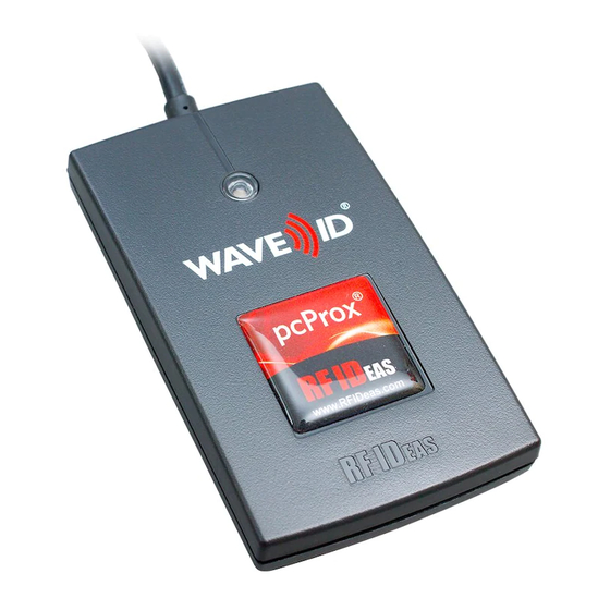
pcProx Plus
User manual
RF IDeas pcProx Plus User Manual
Configuration utility
Hide thumbs
Also See for pcProx Plus
:
Quick start manual
(6 pages)
,
User manual
(95 pages)
1
2
3
Table Of Contents
4
5
6
7
8
9
10
11
12
13
14
15
16
17
18
19
20
21
22
23
24
25
26
27
28
29
30
31
32
33
34
35
36
37
38
39
40
41
42
43
44
45
46
47
48
49
50
51
52
53
54
55
56
57
58
59
60
61
62
63
64
65
66
67
68
69
70
page
of
70
Go
/
70
Contents
Table of Contents
Troubleshooting
Bookmarks
Table of Contents
Thank You
Glossary of Terms
Table of Contents
Chapter 1: The Basics
Wireless Identification Overview
ID Card Reader System
Credential Form Factors
Card Compatibility
Reader Configuration Purposes
Chapter 2:Hardware
What's in Your Part Number
Interface (Connectors)
USB Readers and Wiegand Converters
RS-232 Readers and Converters
Minimum System Requirements
Reader Set-Up Basics
LED Beeper
Chapter 3: Software
Pcprox Configuration Utility
Utility Overview
Menu Tool Bar
Icon Tool Bar
Pcprox Plus Configuration
Standard Configuration
Connect Tab
Output Test Area
Data Format Tab
Delimeters Tab
Timing Tab
SDK Tab
CHUID Tab
Chapter 4: ASCII Command Protocol
ASCII Overview
Connect Serial Communications Program
Command Structure
Help Command
Variable Command
ACP Error Codes
Chapter 5: Tips and Troubleshooting
Troubleshooting
Frequently Asked Questions
Precautions
Before You Call Technical Support
Talking to the Technician
Index
Appendix
Other Products and Accessories
Advertisement
Quick Links
1
Reader Configuration Purposes
2
Pcprox Configuration Utility
3
Sdk Tab
4
Troubleshooting
Download this manual
pcProx® Plus, pcProx® Enroll &
Wiegand Converter
Configuration Utility
User Manual
99009010 Rev U
Table of
Contents
Previous
Page
Next
Page
1
2
3
4
5
Advertisement
Table of Contents
Need help?
Do you have a question about the pcProx Plus and is the answer not in the manual?
Ask a question
Questions and answers
Related Manuals for RF IDeas pcProx Plus
Rfid Systems RF IDeas pcProx User Manual
(95 pages)
Card Reader RF IDeas pcProx Plus Quick Start Manual
Badge readers (6 pages)
RF IDeas AIR ID User Manual
Proximity activated identification (53 pages)
RF IDeas pcProx Enroll User Manual
Configuration utility (70 pages)
This manual is also suitable for:
Pcprox enroll
Wiegand converter
Table of Contents
Print
Rename the bookmark
Delete bookmark?
Delete from my manuals?
Login
Sign In
OR
Sign in with Facebook
Sign in with Google
Upload manual
Upload from disk
Upload from URL


Need help?
Do you have a question about the pcProx Plus and is the answer not in the manual?
Questions and answers