
Related Manuals for Keysight U1452A


Summary of Contents for Keysight U1452A
- Page 1 Keysight U1452A/U1452AT/ U1451A Insulation Tester User’s Guide Distributed by: dataTec ▪ Ferdinand-Lassalle-Str. 52 ▪ 72770 Reutlingen ▪ Tel. 07121 / 51 50 50 ▪ Fax 07121 / 51 50 10 ▪ info@datatec.de ▪ www.datatec.de...
- Page 3 U1452A/U1452AT/U1451A User’s Guide...
- Page 4 1400 Fountaingrove Parkway performance of this document or of Santa Rosa, CA 95403 any information contained herein. Should Keysight and the user have a separate written agreement with WA R N I N G warranty terms covering the material in this document that conflict with...
- Page 5 1000 V current protection Category IV 600 V overvoltage CAT IV Earth (ground) terminal 600 V protection Equipment protected throughout Do not use in distribution systems by double insulation or reinforced with voltages higher than 600 V insulation U1452A/U1452AT/U1451A User’s Guide...
- Page 6 Safety Considerations Read the information below before using this tester. Model U1452A appears in all illustrations. • Do not use the tester if it is damaged. Before you use the tester, inspect the case. WA R N I N G Look for cracks or missing plastic.
- Page 7 • You are advised to use low leakage batteries when changing to new batteries. Please remember to remove the batteries when the tester is not in use for a long period of time. Warning on the risk of battery leakage. U1452A/U1452AT/U1451A User’s Guide...
- Page 8 Altitude Up to 2,000 meters Pollution degree Pollution degree II The U1452A/U1452AT/U1451A Insulation Tester complies with the following safety and EMC N O T E requirements: • Safety compliance • Designed in compliance to IEC/EN 61010-1:2010 for Category III 1000 V and Category IV 600 V •...
- Page 9 The CSA mark is a registered substance elements are expected to trademark of the Canadian Standards leak or deteriorate during normal use. Association. Forty years is the expected useful life of the product. U1452A/U1452AT/U1451A User’s Guide...
- Page 10 “Monitoring and Control Instrument” product. The affixed product label is as shown below. Do not dispose in domestic household waste. To return this unwanted instrument, contact your nearest Keysight Service Center, or visit www.keysight.com/environment/product for more information.
- Page 11 Declaration of Conformity (DoC) The Declaration of Conformity (DoC) for this instrument is available on the Keysight website. You can search the DoC by its product model or description at: http://regulations.products.keysight.com/DoC/search.htm If you are unable to search for the respective DoC, please contact your N O T E local Keysight representative.
- Page 12 THIS PAGE HAS BEEN INTENTIONALLY LEFT BLANK. U1452A/U1452AT/U1451A User’s Guide...
-
Page 13: Table Of Contents
Connect the Bluetooth adapter Your Tester in Brief Dimensions Overview Rotary switch Keypad Display screen Input terminals Cleaning Your Tester Additional Features Automatic power-off Hazardous voltage indication Power-on options Making Measurements Insulation Resistance Test Using the Remote Switch Probe U1452A/U1452AT/U1451A User’s Guide... - Page 14 Performing Limit Comparisons (Limit) Recording Measurement Data (Log) Performing manual logs (HAND) Performing interval logs (AUTO) Performing event logs (TRIG) Reviewing Previously Recorded Data (View) Setup Options Using the Setup Menu Editing numerical values Setup Menu Summary Setup Menu Items U1452A/U1452AT/U1451A User’s Guide...
- Page 15 Changing the button operation on the remote switch probe Changing the Dielectric Absorption Ratio (DAR) for IR tests Characteristics and Specifications Product Characteristics Specification Considerations Measurement Category Electrical Specifications DC specifications AC specifications Capacitance specifications Frequency specifications Sensitivity for voltage measurements U1452A/U1452AT/U1451A User’s Guide XIII...
- Page 16 Insulation resistance specifications Earth-bond resistance specifications EN61557 specifications Display update rate (approximate) U1452A/U1452AT/U1451A User’s Guide...
- Page 17 List of Figures Figure 1-1 Keysight Handheld Meter Logger Software 8 Figure 1-2 Bluetooth adapter connection 9 Figure 1-3 Width dimension 10 Figure 1-4 Height and depth dimensions 11 Figure 1-5 Display screen allocation example 20 Figure 1-6 Connecting the remote switch probe 24...
- Page 18 THIS PAGE HAS BEEN INTENTIONALLY LEFT BLANK. U1452A/U1452AT/U1451A User’s Guide...
- Page 19 List of Tables Table 1-1 Front panel part descriptions 12 Table 1-2 Rear panel parts 13 Table 1-3 U1452A/U1452AT/U1451A rotary switch functions 14 Table 1-4 U1452A/U1452AT/U1451A keypad functions 16 Table 1-5 General annunciators 20 Table 1-6 Measurement units display 22...
- Page 20 Table 5-8 Earth-bond resistance specifications with accuracy of ± [1][2] (% of reading + no. of least significant digit) Table 5-9 Display update rate (approximate) 99 XVIII U1452A/U1452AT/U1451A User’s Guide...
-
Page 21: Introduction
U1452A/U1452AT/U1451A Insulation Tester User’s Guide Introduction About This Manual 2 Documentation map 2 Safety notes 2 Preparing Your Tester 3 Check the shipment 3 Install or change the batteries 3 Turn on your tester 6 Select the range 6 Adjust the tilt stand 7... -
Page 22: About This Manual
User’s Guide. This manual. Quick Start Guide. Printed copy for outdoor use, included with shipment. Service Guide. Downloadable from http://www.keysight.com/find/hhTechLib Keysight Handheld Meter Logger Software, Help, and Quick Start Guide. Downloadable from http://www.keysight.com/hhmeterlogger Safety notes The following safety notes are used throughout this manual. More pertinent safety notes for using this product are located under the “Safety... -
Page 23: Preparing Your Tester
U1452A/U1452AT/U1451A Quick Start Guide. 3 For any question or problems, refer to the Keysight contact numbers on the back of this manual. Install or change the batteries Your tester is powered by four 1.5 V AA alkaline batteries (included in the... - Page 24 Insert four 1.5 V AA batteries. 6 Ensure that the inner rubber cover is positioned properly. 7 Replace the battery cover back in its original position and tighten the screws. 8 Finally fit the orange rubber holster back on the tester. U1452A/U1452AT/U1451A User’s Guide...
- Page 25 To avoid instruments being damage from battery leakage: C A U T I O N • Always remove dead batteries immediately. • Always remove the batteries and store them separately if the tester is not going to be used for a long period. U1452A/U1452AT/U1451A User’s Guide...
-
Page 26: Turn On Your Tester
To power ON your tester, turn the rotary switch from the position to any other position. Select the range The tester’s selected range is always displayed on the right- hand end of the bar graph. Selected range Autoranging indicator U1452A/U1452AT/U1451A User’s Guide... -
Page 27: Adjust The Tilt Stand
> is shown on the display instead. Adjust the tilt stand To adjust the tester to a 60° standing position, pull the tilt- stand outward to its maximum reach. IR-USB cable To PC (host) Pull until maximum reach U1452A/U1452AT/U1451A User’s Guide... -
Page 28: Connect To The Handheld Meter Logger Software
PC. Ensure that the Keysight logo on the U1173A IR- USB cable connected to the tester is facing up. Firmly push the IR head into the tester’s IR communication port until it snaps into place. -
Page 29: Connect The Bluetooth Adapter
Figure 1- Bluetooth adapter Figure 1-2 Bluetooth adapter connection Refer to the Keysight U1117A IR- to- Bluetooth Adapter Operating Instructions (download from http://www.keysight.com/find/U1117A) for more information on how to set up the U1117A to a Windows PC, Android device, or iOS device. -
Page 30: Your Tester In Brief
Introduction Your Tester in Brief Your Tester in Brief Dimensions Front view 100 mm Figure 1-3 Width dimension U1452A/U1452AT/U1451A User’s Guide... -
Page 31: Figure 1-4 Height And Depth Dimensions
Introduction Your Tester in Brief Rear and side view 58 mm 218 mm Figure 1-4 Height and depth dimensions U1452A/U1452AT/U1451A User’s Guide... -
Page 32: Overview
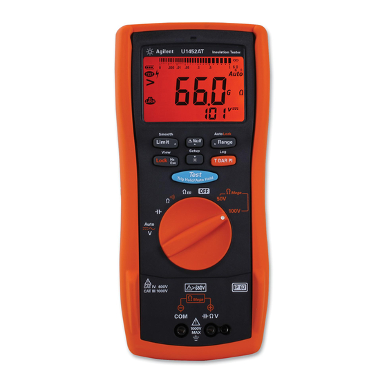
The front panel parts of your tester are described in this section. Table 1-1 Front panel part descriptions Legend Description Learn more on: Red LED indicator page 54 Display screen page 20 Keypad page 16 Rotary switch page 14 Input terminals page 24 U1452A/U1452AT/U1451A User’s Guide... -
Page 33: Table 1-2 Rear Panel Parts
Table 1-2 Rear panel parts Legend Description Learn more on: IR communication port page 8 Test lead/probe holders Battery access (under the orange rubber holster) page 3 Tilt stand page 7 Fuse access (under the orange rubber holster) U1452A/U1452AT/U1451A User’s Guide... -
Page 34: Rotary Switch
N O T E resistance tests. See page 16 for more information on the key. U1452A U1452AT U1451A Table 1-3 U1452A/U1452AT/U1451A rotary switch functions Legend Measurement function U1452A U1452AT U1451A Learn more on: ✔ ✔... - Page 35 Introduction Your Tester in Brief Table 1-3 U1452A/U1452AT/U1451A rotary switch functions (continued) Legend Measurement function U1452A U1452AT U1451A Learn more on: ✔ ✔ 100 V Insulation resistance test ✔ ✔ - Timed test page 38 ✔ ✔ - Dielectric Absorption Ratio test ✔...
-
Page 36: Keypad
Turning the rotary switch to another position resets the current operation of the key. U1452A/U1452AT U1451A Table 1-4 U1452A/U1452AT/U1451A keypad functions Function when pressed for: Legend Less than 1 second More than 1 second Ω... - Page 37 Introduction Your Tester in Brief Table 1-4 U1452A/U1452AT/U1451A keypad functions (continued) Function when pressed for: Legend Less than 1 second More than 1 second Lock: Press to lock the insulation test or View: Press and hold to enter the Log earth-bond resistance test (when the rotary Review menu.
- Page 38 Introduction Your Tester in Brief Table 1-4 U1452A/U1452AT/U1451A keypad functions (continued) Function when pressed for: Legend Less than 1 second More than 1 second Limit: Press to enable the comparison for limit mode. Smooth: Press and hold to smoothen the •...
- Page 39 Introduction Your Tester in Brief Table 1-4 U1452A/U1452AT/U1451A keypad functions (continued) Function when pressed for: Legend Less than 1 second More than 1 second Setup: Press and hold to enter the Setup menu. • In the Setup menu, press navigate through the menu pages. Press at each menu page to move the cursor to a specific menu item.
-
Page 40: Display Screen
Figure 1-5 Display screen allocation example Table 1-5 General annunciators Legend Description Remote control enabled Battery capacity indication Analog bar graph Test indication for insulation resistance and earth-bond resistance tests Hazardous voltage sign for measuring voltage ≥30 V or OL (overload) U1452A/U1452AT/U1451A User’s Guide... - Page 41 Test and Test Lock indication for insulation resistance and earth-bond resistance tests Primary display AC or DC indication Measuring units for primary display Test time indication for earth-bond resistance and insulation resistance tests APO (Auto Power-Off) enabled Limit comparison enabled Data logging in progress U1452A/U1452AT/U1451A User’s Guide...
-
Page 42: Table 1-6 Measurement Units Display
Table 1-6 Measurement units display Sign/Notation Description Giga 1E+09 (1000000000) Mega 1E+06 (1000000) kilo 1E+03 (1000) nano 1E–09 (0.000000001) μ micro 1E–06 (0.000001) milli 1E–03 (0.001) mV, V Voltage, units for voltage measurement nF, μF, mF Farad, units for capacitance measurement U1452A/U1452AT/U1451A User’s Guide... -
Page 43: Table 1-7 Analog Bar Graph Display
Each segment is presented as a ratio to the range value indicated on the peak bar- graph. The unit and range will be indicated according to various measurements (see Table 1- Table 1-7 Analog bar graph display Function Bar graph Ω , Ω Ω Mega U1452A/U1452AT/U1451A User’s Guide... -
Page 44: Input Terminals
440 mA/1000 V, 30 kA fast-acting fuse The remote switch probe is used for insulation resistance (IR) and earth-bond resistance (EBR) tests. Remote switch probe terminal for IR and EBR tests Figure 1-6 Connecting the remote switch probe U1452A/U1452AT/U1451A User’s Guide... -
Page 45: Cleaning Your Tester
2 Turn the tester over, and shake out any dirt that may have accumulated in the terminals. Wipe the case with a damp cloth and mild detergent — do not use abrasives or solvents. Wipe the contacts in each terminal with a clean swab dipped in alcohol. U1452A/U1452AT/U1451A User’s Guide... -
Page 46: Additional Features
Simulates the Auto Power-Off (APO) mode. Press any key to turn the tester back on and resume normal operation. Checks firmware version. The tester’s firmware version will be shown on the primary display. Press any key to exit this mode. U1452A/U1452AT/U1451A User’s Guide... - Page 47 U1451A Change the resolution count to high. To permanently enable change the resolution count. See “Changing the display count” on page U1452A/U1452AT Tests the LCD. All LCD annunciators are lighted. Press any key to exit this mode. U1452A/U1452AT/U1451A User’s Guide...
- Page 48 Introduction Additional Features THIS PAGE HAS BEEN INTENTIONALLY LEFT BLANK. U1452A/U1452AT/U1451A User’s Guide...
-
Page 49: Making Measurements
U1452A/U1452AT/U1451A Insulation Tester User’s Guide Making Measurements Insulation Resistance Test 30 Using the Remote Switch Probe 32 Locking the test 33 Timed insulation resistance/earth-bond resistance test 34 Measuring the Dielectric Absorption Ratio (DAR) 35 Measuring the Polarization Index (PI) 36... -
Page 50: Insulation Resistance Test
Setup), the test is inhibited. The symbol is shown on the display when either the external voltage or the test voltage is greater than 30 V. Disconnect the tester and remove the power of the circuit before proceeding. U1452A/U1452AT/U1451A User’s Guide... -
Page 51: Figure 2-1 Insulation Resistance Test Example
Making Measurements Insulation Resistance Test Remote Switch Probe Hold Test will continue until is released. Figure 2-1 Insulation resistance test example U1452A/U1452AT/U1451A User’s Guide... -
Page 52: Using The Remote Switch Probe
Remote Switch Probe. By default the button on the Remote Switch Probe emulates the button on the tester. To change the default button operation, see “Changing the button operation on the remote switch probe” on page 82 U1452A/U1452AT/U1451A User’s Guide... -
Page 53: Locking The Test
“Changing the Dielectric Absorption Ratio (DAR) for IR tests” on page 83 to disable this feature. If you disable this feature, you will need to press to unlock the tester, even if the test has already stopped. U1452A/U1452AT/U1451A User’s Guide... -
Page 54: Timed Insulation Resistance/Earth-Bond Resistance Test
Press Press select the timed test. to start the test. view the timer. Press again to stop the test. Press to view After 30 seconds. the resistance value. After 1 minute, time up. Figure 2-2 T/Time operation U1452A/U1452AT/U1451A User’s Guide... -
Page 55: Measuring The Dielectric Absorption Ratio (Dar)
Press to view After 30 seconds. Error as IR (t0) > maximum range the resistance value. After 1 minute, time up. DAR > 999.9 Press to view t0. Press to view t00. Figure 2-3 DAR operation U1452A/U1452AT/U1451A User’s Guide... -
Page 56: Measuring The Polarization Index (Pi)
Press to view After 1 minute. Error as IR (t0) > maximum range the resistance value. After 10 minutes, time up. PI > 999.9 Press to view t0. Press to view t00. Figure 2-4 PI operation U1452A/U1452AT/U1451A User’s Guide... -
Page 57: Viewing The Leakage Current
Viewing the leakage current Press to view the leakage current display. The leakage current display is related to the insulation resistance. The higher the resistance tested, the lower the current is to be measured. U1452A/U1452AT/U1451A User’s Guide... -
Page 58: Earth-Bond Resistance Test
When the source voltage is <4.7 V, the tester will inhibit the test automatically. The secondary display indicates the voltage (with auto-ranging enabled). • The APO (auto power-off) function is disabled during the test. • See also “Timed insulation resistance/earth-bond resistance test” on page U1452A/U1452AT/U1451A User’s Guide... -
Page 59: Figure 2-5 Earth-Bond Resistance Test Example
Making Measurements Earth-Bond Resistance Test Remote Switch Probe Hold > Test will continue until is released. Figure 2-5 Earth-bond resistance test example U1452A/U1452AT/U1451A User’s Guide... - Page 60 2 Press and hold to verify the fuse condition. 3 If the fuse has been blown, FUSE will be shown on the display. Follow the instructions in the U1452A/U1452AT/U1451A Service Guide to replace the fuse. Fuse blown; replace fuse.
-
Page 61: Measuring Ac Or Dc Voltage
• This tester displays DC voltage values as well as their polarity. Negative DC voltages will N O T E return a negative sign on the left of the display. • Press to measure the frequency of the voltage source. See “Measuring Frequency” on page 44 to learn more. U1452A/U1452AT/U1451A User’s Guide... -
Page 62: Figure 2-6 Ac Or Dc Voltage Measurement Example
Making Measurements Measuring AC or DC Voltage Figure 2-6 AC or DC voltage measurement example U1452A/U1452AT/U1451A User’s Guide... -
Page 63: Auto Ac Or Dc Signal Identification
While the signal is being identified, you can press to lock the (AC or DC) signal on the primary display. to stop the Auto function and lock the At any time, you can press identified signal component (AC or DC). U1452A/U1452AT/U1451A User’s Guide... -
Page 64: Measuring Frequency
• If a reading shows as 0 Hz or is unstable, the input signal may be below or near the trigger level. You can usually correct these problems by manually selecting a lower input range, which increases the sensitivity of the tester. U1452A/U1452AT/U1451A User’s Guide... -
Page 65: Figure 2-7 Definition Of Frequency
The bar graph does not indicate frequency but indicates the voltage value of the input signal. Rise Time Fall Time + Width – Width Period Figure 2-7 Definition of frequency U1452A/U1452AT/U1451A User’s Guide... -
Page 66: Measuring Resistance
• Because the tester’s test current flows through all possible paths between the probe tips, the measured value of a resistor in a circuit is often different from the resistor’s rated value. U1452A/U1452AT/U1451A User’s Guide... -
Page 67: Figure 2-8 Resistance Measurement Example
Making Measurements Measuring Resistance Figure 2-8 Resistance measurement example U1452A/U1452AT/U1451A User’s Guide... -
Page 68: Continuity Test
• The continuity function detects intermittent shorts and opens. A brief short causes the tester to emit a short beep. • You can enable or disable the audible alert via the Setup. See “Changing the continuity alert” on page 74 for more information on the audible alert option. U1452A/U1452AT/U1451A User’s Guide... -
Page 69: Figure 2-9 Continuity Test Example
Making Measurements Continuity Test (open) (closed) Figure 2-9 Continuity test example U1452A/U1452AT/U1451A User’s Guide... -
Page 70: Measuring Capacitance
• The tester measures capacitance by using an AC sine wave. N O T E • The resistance of the test leads will impact the accuracy of the measurement. It is recommended to use short leads to measure capacitance. • The test frequency is 54.5 Hz. U1452A/U1452AT/U1451A User’s Guide... -
Page 71: Figure 2-10 Capacitance Measurement Example
Making Measurements Measuring Capacitance Figure 2-10 Capacitance measurement example U1452A/U1452AT/U1451A User’s Guide... - Page 72 Making Measurements Measuring Capacitance THIS PAGE HAS BEEN INTENTIONALLY LEFT BLANK. U1452A/U1452AT/U1451A User’s Guide...
- Page 73 U1452A/U1452AT/U1451A Insulation Tester User’s Guide Tester Features Making Relative Measurements (Null) 54 Freezing the Display (TrigHold and AutoHold) 55 Performing Limit Comparisons (Limit) 57 Recording Measurement Data (Log) 59 Performing manual logs (HAND) 60 Performing interval logs (AUTO) 60 Performing event logs (TRIG) 61...
-
Page 74: Tester Features
Press zero-adjust the display. • For DC voltage measurements, the thermal effect will influence the accuracy of the measurements. Short the test leads and press when the displayed value is stable to zero-adjust the display. U1452A/U1452AT/U1451A User’s Guide... -
Page 75: Freezing The Display (Trighold And Autohold)
Press and hold to exit this mode. Ω or the Ω Pressing and holding when the rotary switch is in one of the position Mega N O T E will result in a test being performed instead. U1452A/U1452AT/U1451A User’s Guide... - Page 76 To change the default AutoHold threshold count see “Changing the variation count” on page 71 for more information. If the reading value is unable to reach a stable state, the reading value will not be updated. N O T E U1452A/U1452AT/U1451A User’s Guide...
-
Page 77: Performing Limit Comparisons (Limit)
0, 00, or left blank along with any unit combination (see Table 3- 3 Position the cursor on the > annunciator to change the Limit pass condition (< or >). 4 Press to save your changes (or press to discard your changes). U1452A/U1452AT/U1451A User’s Guide... - Page 78 • The red LED blinks thrice When the Limit feature is enabled for insulation resistance tests, the red LED indicator N O T E lights up accordingly to the changes in the limit values instead of blinking every 2 seconds. U1452A/U1452AT/U1451A User’s Guide...
-
Page 79: Recording Measurement Data (Log)
Before starting a recording session, set up the tester for the measurements to be recorded. To change the Log option see “Changing the recording option” on page 80 for more information. “Reviewing Previously Recorded Data (View)” on page 63 to review or erase the recorded entries. U1452A/U1452AT/U1451A User’s Guide... -
Page 80: Performing Manual Logs (Hand)
Subsequent readings are automatically recorded into the tester’s memory at the interval specified in the Setup. 2 Press and hold again to exit the interval log mode. U1452A/U1452AT/U1451A User’s Guide... -
Page 81: Performing Event Logs (Trig)
Voltage, frequency, When the input signal varies more than the Voltage, resistance, or AutoHold capacitance cable length, variation count and the reading update is stable. capacitance or output source voltage U1452A/U1452AT/U1451A User’s Guide... - Page 82 The maximum number of readings that can be stored for the event log is 100 entries. When all entries are occupied, will be shown when you press and hold APO (auto power-off) is disabled during the recording session. N O T E U1452A/U1452AT/U1451A User’s Guide...
-
Page 83: Reviewing Previously Recorded Data (View)
The data sanitization operation may take up to 30 seconds to complete. Do not press C A U T I O N any keys or turn the rotary switch until the data sanitization operation is completed. U1452A/U1452AT/U1451A User’s Guide... - Page 84 Tester Features Reviewing Previously Recorded Data (View) THIS PAGE HAS BEEN INTENTIONALLY LEFT BLANK. U1452A/U1452AT/U1451A User’s Guide...
- Page 85 U1452A/U1452AT/U1451A Insulation Tester User’s Guide Setup Options Using the Setup Menu 66 Editing numerical values 67 Setup Menu Summary 68 Setup Menu Items 71 Editing numerical values 67 Changing the variation count 71 Enabling smooth mode 71 Changing the beep frequency 72...
-
Page 86: Setup Options
• Press to save your changes. • While the menu item’s value is flashing, press to discard your changes. The tester will automatically exit the Setup menu after 30 seconds of inactivity. N O T E U1452A/U1452AT/U1451A User’s Guide... -
Page 87: Editing Numerical Values
1 second to enter the Setup menu. Press to edit the Press selected menu item’s value. move the cursor left or right. Press to increment or decrement the selected digit. Press again to save the changes made. U1452A/U1452AT/U1451A User’s Guide... -
Page 88: Setup Menu Summary
Default is a beep (bEEE). Change the battery selection from primary (PRi) to secondary (SEC). PRi or SEC page 75 Default is primary (PRi). yES or no Reset the tester to its factory default settings. page 76 U1452A/U1452AT/U1451A User’s Guide... - Page 89 Set the maximum inhibit voltage for insulation resistance test. 30 V, 50 V, or 75 V page 81 Default is 30 V. Enable or disable the lock once feature. yES or no page 82 Default is enabled (yES). U1452A/U1452AT/U1451A User’s Guide...
- Page 90 Change or disable the button operation on the remote probe. bt-1 to bt-7 page 82 (d or E) Default is (bt-7 Set the Dielectric Absorption Ratio in seconds (60:30 or 60:15). 60.30 or 60.15 seconds page 83 Default is 60:30 (seconds). U1452A/U1452AT/U1451A User’s Guide...
-
Page 91: Setup Menu Items
The variation count is set to the value used for the AutoHold feature (see “Changing the variation count” on page 71). U1452A/U1452AT/U1451A User’s Guide... -
Page 92: Changing The Beep Frequency
2 Browse to , and press to edit the value. 3 Use the arrow keys to change the beep frequency. Select to disable the beeper. 4 Press to save your changes (or press to discard your changes). U1452A/U1452AT/U1451A User’s Guide... -
Page 93: Changing The Auto Power-Off (Apo) Timer
Changing the LCD backlight timeout The tester’s LCD backlight uses a timer to determine when to turn off the LCD backlight. Legend Range Default setting • (01 to 99) seconds • E(nabled) or d(isabled) U1452A/U1452AT/U1451A User’s Guide... -
Page 94: Changing The Continuity Alert
3 Use the arrow keys to change the continuity alert. 4 Press to save your changes (or press to discard your changes). 5 Press and hold until the tester restarts to return to normal operation. U1452A/U1452AT/U1451A User’s Guide... -
Page 95: Disabling The Power-On Melody
, and press to edit the value. 3 Use the arrow keys to change the power- on melody. Select disable the power- on melody. option is for Keysight internal use. USEr N O T E 4 Press to save your changes (or press to discard your changes). -
Page 96: Resetting The Tester's Setup Options
Use these settings to change the display count for the following measurements/tests. The low resolution count is a tenth of the original display count. As an example, if the original display count is 6000 counts, then the low resolution display count is 600 counts. U1452A/U1452AT/U1451A User’s Guide... -
Page 97: Changing The Cable Length Unit
To change the cable length unit: 1 Press for more than 1 second to enter the Setup menu. 2 Browse to , and press to edit the value. 3 Use the arrow keys to change the cable length unit. U1452A/U1452AT/U1451A User’s Guide... -
Page 98: Changing The Cable Length Scale
Changing the alert indicators The tester’s audible and visual alerts users to the presence of circuit continuities (see page 48) and values exceeding the Limit values set (see page 48). Legend Range Default setting bE.rL, --.rL, bE.--, or --.-- bE.rL U1452A/U1452AT/U1451A User’s Guide... -
Page 99: Changing The Sample Interval Duration
3 Use the arrow keys to change the sample interval duration. 4 Press to save your changes (or press to discard your changes). 5 Press and hold until the tester restarts to return to normal operation. U1452A/U1452AT/U1451A User’s Guide... -
Page 100: Changing The Recording Option
This setting is used with insulation resistance tests (see page 38) or earth- bond resistance measurements (see page 38). The tester performs the test over the timed period defined in this setting. Legend Range Default setting (00.05 to 59.59) mm:ss 00.10 U1452A/U1452AT/U1451A User’s Guide... -
Page 101: Changing The Maximum Inhibit Voltage For Ir Tests
3 Use the arrow keys to change the value of the inhibit voltage. 4 Press to save your changes (or press to discard your changes). 5 Press and hold until the tester restarts to return to normal operation. U1452A/U1452AT/U1451A User’s Guide... -
Page 102: Disabling The Lock Once Feature
Changing the button operation on the remote switch probe This setting is used with the remote switch probe. The button operation on the remote switch probe will emulate the function selected in this setting. U1452A/U1452AT/U1451A User’s Guide... -
Page 103: Changing The Dielectric Absorption Ratio (Dar) For Ir Tests
Default setting (60.30 or 60.15) seconds 60.30 To change the DAR ratio: 1 Press for more than 1 second to enter the Setup menu. 2 Browse to is shown on the display), and press to edit the value. U1452A/U1452AT/U1451A User’s Guide... - Page 104 3 Use the arrow keys to change the value of the DAR ratio. 4 Press to save your changes (or press to discard your changes). 5 Press and hold until the tester restarts to return to normal operation. U1452A/U1452AT/U1451A User’s Guide...
-
Page 105: Characteristics And Specifications
AC specifications 91 Capacitance specifications 92 Frequency specifications 93 Sensitivity for voltage measurements 94 Insulation resistance specifications 95 Earth-bond resistance specifications 97 EN61557 specifications 97 Display update rate (approximate) 99 This chapter lists the characteristics, considerations, and specifications of the U1452A/U1452AT/U1451A tester. -
Page 106: Product Characteristics
STORAGE COMPLIANCE Refer to “Environmental Conditions” on page VI SAFETY AND EMC COMPLIANCE Refer to “Environmental Conditions” on page VI SURGE PROTECTION 8 kV peak per IEC1010.1-92 (IEC1010-1) MEASUREMENT CATEGORY CAT III 1000 V/CAT IV 600 V U1452A/U1452AT/U1451A User’s Guide... - Page 107 • Three months for the product’s standard accessories, unless otherwise specified • Please take note that for the product, the warranty does not cover: • Damage from contamination • Normal wear and tear of mechanical components • Manuals, fuses, and standard disposable batteries CALIBRATION CYCLE One year U1452A/U1452AT/U1451A User’s Guide...
-
Page 108: Specification Considerations
23 °C ± 5 °C, with relative humidity less than 80% RH. • The AC measurement is calibrated for sine waves only. Measurement Category The Keysight U1452A/U1452AT/U1451A tester has a safety rating of CAT III, 1000 V and CAT IV, 600 V. Measurement CAT I are for measurements performed on circuits not directly connected to the AC mains. -
Page 109: Electrical Specifications
10 MΩ (nominal) Voltage 600 V 0.1 V 0.5% + 2 0.2% + 2 10 MΩ (nominal) 1000 V 0.5% + 2 0.2% + 2 10 MΩ (nominal) Notes: 1 DC V overload protection: 1000 V RMS. U1452A/U1452AT/U1451A User’s Guide... -
Page 110: Table 5-2 Resistance Specifications With Accuracy Of ± (% Of Reading + No. Of Least Significant Digit)
The built-in buzzer beeps when the resistance measured is less than 30 Ω ± 15 Ω. • • The accuracy is specified after the Null function is used to subtract the test lead resistance and thermal effect (by shorting the test leads). U1452A/U1452AT/U1451A User’s Guide... -
Page 111: Ac Specifications
1 The following statements are true for resistance measurements: • AC V overload protection: 1000 V • AC V input impedance: 10 MΩ in parallel with <100 pF (nominal). • The input signal is lower than the product of 1,000,000 V×Hz. U1452A/U1452AT/U1451A User’s Guide... -
Page 112: Capacitance Specifications
(by opening the test leads). 3 The maximum display is 1200 counts. 4 Add additional accuracy of 0.1% per μF for values greater than 50 μF — for example 100 μF, additional accuracy of 5% is to be added. U1452A/U1452AT/U1451A User’s Guide... -
Page 113: Frequency Specifications
1 Overload protection: 1000 V; input signal is <1,000,000 V × Hz (product of voltage and frequency). 2 The frequency measurement is susceptible to error when measuring low-voltage and low-frequency signals. Shielding inputs from external noise pickup is critical for minimizing measurement errors. U1452A/U1452AT/U1451A User’s Guide... -
Page 114: Sensitivity For Voltage Measurements
Minimum sensitivity (RMS sine wave) Input range 2 Hz to 400 Hz 0.5 V 60 V 600 V 65 V 1000 V 65 V Notes: 1 Maximum input for specified accuracy, refer to “AC specifications” on page U1452A/U1452AT/U1451A User’s Guide... -
Page 115: Table 5-7 Insulation Resistance Specifications With Accuracy Of ± (% Of Reading + No. Of Least Significant Digit)
1.5% + 5 60 MΩ 0.01 MΩ 1.5% + 5 1000 V 600 MΩ 0.1 MΩ 1.5% + 5 1 mA @ 1 MΩ <1 GΩ 0.001 GΩ 1.5% + 5 ~200 GΩ ~0.1 GΩ 1.5% + 5 U1452A/U1452AT/U1451A User’s Guide... - Page 116 50 V Above 1 GΩ 500 MΩ 250 MΩ 100 MΩ 50 MΩ Basic accuracy 1.5% + 5 1.5% + 5 1.5% + 5 2.0% + 5 2.0% + 5 Additional accuracy 0.1%/GΩ 0.2%/GΩ 0.4%/GΩ 1.0%/GΩ 2.0%/GΩ U1452A/U1452AT/U1451A User’s Guide...
-
Page 117: Earth-Bond Resistance Specifications
Intrinsic uncertainty Measurement Operating uncertainty U1451A U1452A/U1452AT Voltage ± (0.5% + 2) ± (0.2% + 2) Notes: 1 The maximum resistance to meet the standard of EN61557-1, 5.2.4, which indicates the maximum amount allowed as less than 30%. U1452A/U1452AT/U1451A User’s Guide... - Page 118 3 Test voltage/maximum range for different models: Test voltage U1451A U1452A U1452AT 50 V 60 GΩ 60 GΩ 100 V 60 GΩ 60 GΩ 250 V 60 GΩ 200 GΩ 500 V 60 GΩ 200 GΩ 1000 V 60 GΩ 200 GΩ U1452A/U1452AT/U1451A User’s Guide...
-
Page 119: Display Update Rate (Approximate)
Characteristics and Specifications Electrical Specifications Display update rate (approximate) Table 5-9 Display update rate (approximate) Function Times/Second AC V DC V Ω Capacitance Frequency 1 (>10 Hz) U1452A/U1452AT/U1451A User’s Guide... - Page 120 Characteristics and Specifications Electrical Specifications THIS PAGE HAS BEEN INTENTIONALLY LEFT BLANK. U1452A/U1452AT/U1451A User’s Guide...
- Page 121 (tel) 0800 047 866 (fax) 0800 286 331 Other Asia Pacific Countries: (tel) (65) 6375 8100 (fax) (65) 6755 0042 Or visit Keysight World Wide Web at: www.keysight.com/find/assist Product specifications and descriptions in this document are subject to change without notice. Always refer to Keysight...
- Page 122 This information is subject to change without notice. © Keysight Technologies 2014 Edition 3, December 5, 2014 *U1451-90003* U1451-90003 www.keysight.com...
Need help?
Do you have a question about the U1452A and is the answer not in the manual?
Questions and answers