Table of Contents
Advertisement
Quick Links
Advertisement
Table of Contents

Subscribe to Our Youtube Channel
Related Manuals for Keysight U1610A


Summary of Contents for Keysight U1610A
- Page 1 Keysight U1610/20A Handheld Digital Oscilloscope User’s Guide...
-
Page 2: Safety Information
Declaration of Conformity. and the DFARS and are set forth specifically in writing elsewhere in the WARNING EULA. Keysight shall be under no obligation to update, revise or A WARNING notice denotes a hazard. It otherwise modify the Software. With... -
Page 3: Safety Symbols
Both direct and alternating Category II overvoltage CAT II current protection Caution, risk of danger (refer to this manual for specific Category III overvoltage CAT III Warning or Caution protection information) Caution, risk of electric shock Keysight U1610/20A User’s Guide... -
Page 4: General Safety Information
Failure to comply with these precautions or with specific warnings elsewhere in this manual violates safety standards of design, manufacture, and intended use of the instrument. Keysight Technologies assumes no liability for the customer’s failure to comply with these requirements. - Page 5 – Meter input - From any terminal to earth ground - CAT III 600 Vrms – Scope input - From any terminal to earth ground - CAT III 300 Vrms Refer to the respective probe's manual for more information on the specification. Keysight U1610/20A User’s Guide...
- Page 6 – Handle sensitive components to the minimum extent possible. Do not allow contacts between components and exposed connector pins. – Transport and store in ESD preventive bags or containers that protect sensitive components from static electricity. – The battery (optional) must be properly recycled or disposed. Keysight U1610/20A User’s Guide...
-
Page 7: Measurement Category
Measurement CAT IV Measurements performed at the source of the low-voltage installation. Examples are electricity meters and measurements on primary overcurrent protection devices and ripple control units. Keysight U1610/20A User’s Guide... -
Page 8: Environmental Conditions
– 35 °C to 40 °C (with power adapter) – 35 °C to 50 °C (with battery only) Storage condition: – Up to 95% RH at 40 °C (non-condensing) Altitude Up to 2000 m Pollution degree Keysight U1610/20A User’s Guide... - Page 9 CAN/CSA-C22.2 No. 61010-2-033-12 – USA: ANSI/UL Std. No. 61010-1:2012 ANSI/UL Std. No. 61010-2-030 (1st Edition) ANSI/UL Std. No. 61010-2-033 (1st Edition) – IEC 61326-1:2012/EN 61326-1:2013 – Australia/New Zealand: AS/NZS CISPR 11:2011 – Canada: ICES/NMB-001: ISSUE 4, June 2006 Keysight U1610/20A User’s Guide...
-
Page 10: Regulatory Markings
Industrial Scientific and Medical household waste. Group 1 Class A product. Product contains restricted The CSA mark is a registered substance(s) above maximum value, trademark of the Canadian Standards with a 40-year Environmental Association. Protection Use Period. Keysight U1610/20A User’s Guide... -
Page 11: Waste Electrical And Electronic Equipment (Weee) Directive 2002/96/Ec
To return this unwanted instrument, contact your nearest Keysight Service Center, or visit http://about.keysight.com/en/companyinfo/environment/takeback.shtml for more information. Sales and Technical Support To contact Keysight for sales and technical support, refer to the support links on the following Keysight websites: – www.keysight.com/find/handheldscope (product-specific information and support, software anddocumentation updates) –... - Page 12 THIS PAGE HAS BEEN INTENTIONALLY LEFT BLANK. Keysight U1610/20A User’s Guide...
-
Page 13: Table Of Contents
......... .35 Keysight U1610/20A User’s Guide... - Page 14 ......... . 63 Waveform Acquisition Controls ....... 64 Keysight U1610/20A User’s Guide...
- Page 15 ........100 Keysight U1610/20A User’s Guide...
- Page 16 ........115 Characteristics and Specifications Keysight U1610/20A User’s Guide...
- Page 17 ......102 Figure 5-2 Scope logger display ......103 Keysight U1610/20A User’s Guide...
- Page 18 ..... . 113 Figure 6-5 Service function submenu ..... 114 Keysight U1610/20A User’s Guide...
-
Page 19: Getting Started
Keysight U1610/20A Handheld Digital Oscilloscope User’s Guide Getting Started Introduction Package Contents Optional Accessories Adjust the Hand Strap Install the Neck Strap Charge the Battery Tilt the Handheld Scope Power On/Off the Handheld Scope Use the Function Softkeys Access the Quick Help... -
Page 20: Introduction
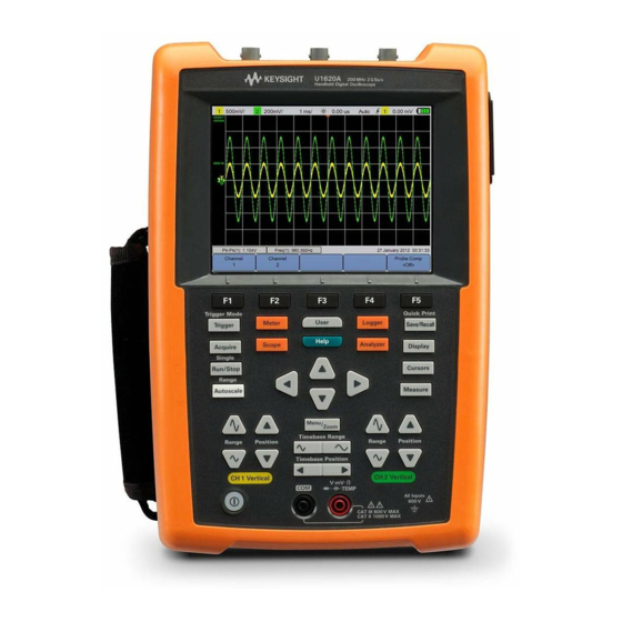
The U1610A and U1620A models have 100 MHz and 200 MHz bandwidths with maximum real-time sample rates of 1 GSa/s and 2 GSa/s respectively. With its 5.7-inch LCD color display, the U1610/20A oscilloscope is capable of clearly distinguishing waveforms from two channels. -
Page 21: Package Contents
If the shipping container is damaged or the cushioning materials show signs of stress, notify the carrier and your nearest Keysight Sales Office. Keep the damaged shipping container or cushioning material until you have inspected the contents of the shipment for completeness and have checked the handheld scope mechanically and electrically. -
Page 22: Optional Accessories
For better grip, peel open the strap and adjust the two velcro strips as shown below. Install the Neck Strap Thread the velcro strip through the strap hole. Adjust the strap to the maximum length and secure it as shown below. Keysight U1610/20A User’s Guide... -
Page 23: Charge The Battery
AC/DC adapter provided. If the battery is fully discharged after subsequent use, charge the battery with the handheld scope turned on. The power key will turn constant yellow when the battery is fully charged. Keysight U1610/20A User’s Guide... -
Page 24: Tilt The Handheld Scope
Getting Started Tilt the Handheld Scope For proper handling during operation, tilt the handheld scope as shown below. Lift the tilt-stand and pull outwards Keysight U1610/20A User’s Guide... -
Page 25: Power On/Off The Handheld Scope
To view Help in another language, press > > and use the keys to select the language. Press again to exit the selection menu. To access information on using Help, press and hold for approximately 3 seconds. Keysight U1610/20A User’s Guide... -
Page 26: Reset The Handheld Scope
Before resetting the handheld scope, you may want to save the current NOTE configuration for later use by pressing > . See Chapter 3, “Save and Recall Controls” on page 85. Figure 1-1 Default Settings function Keysight U1610/20A User’s Guide... -
Page 27: Perform Self-Calibration
– To maximize the measurement accuracy. – After experiencing abnormal operation. – To verify proper operation after repairing. Disconnect all probe and meter connections to the input terminals of the WARNING handheld scope before performing self-calibration. Keysight U1610/20A User’s Guide... -
Page 28: Set The Date And Time And Language
Scope mode. Press and use the keys to set any of the 10 languages (English, Spanish, French, Italian, German, Portuguese, Simplified Chinese, Traditional Chinese, Japanese or Korean). Press again to exit the selection menu. Keysight U1610/20A User’s Guide... -
Page 29: Connect Probes To Oscilloscope Terminals
Getting Started Connect Probes to Oscilloscope Terminals Connect the handheld scope in either single channel or dual channels with scope probes as shown below. Keysight U1610/20A User’s Guide... -
Page 30: Compensate The Scope Probe
4 The input signal is 5 Vpp, 1 kHz from the external trigger. BNC adapter Use a nonmetallic tool to adjust the trimmer capacitor on the probe for the flattest pulse possible. Keysight U1610/20A User’s Guide... -
Page 31: Figure 1-3 Trimmer Capacitor
Getting Started trimmer Figure 1-3 Trimmer capacitor Properly compensated Over compensated Under compensated Figure 1-4 Pulse shape reference Keysight U1610/20A User’s Guide... -
Page 32: Independently Isolated Scope Input Channels
Figure 1-6. Instruments with channel-to-channel isolation can be used to eliminate the ground loops. Isolated channels separate the two signal path effectively from each other by eliminating any potential common circuit path between the two inputs. Keysight U1610/20A User’s Guide... -
Page 33: Figure 1-6 Ground Loop
Each input channel (CH1, CH2, and Ext. Trig) is isolated with Keysight isolation technology architecture and the ground leads are referred to any ground potential as shown in Figure 1-7. -
Page 34: Figure 1-7 Channel Isolation Block Diagram
The handheld scope input channels are fully isolated and provide channel-to-power line isolation, channel-to-USB connectivity isolation, and channel-to-keypad isolation. You can connect to signals with different voltage reference levels safely and obtain accurate measurements. Keysight U1610/20A User’s Guide... -
Page 35: Figure 1-8 Insulation Cover
For a complete floating measurement, the probe reference lead for each channel is connected to the circuitry. Figure 1-9 Probing the VFD IGBT control signal and IGBT output Keysight U1610/20A User’s Guide... -
Page 36: Floating Measurement With Isolated Probes At Cat Iii 600 V
CAT III 600 V with a 10:1 probe, the signal will be attenuated 10 times. The actual voltage flow into the BNC input will be CAT III 60 V, which is within the maximum input voltage rating. Keysight U1610/20A User’s Guide... -
Page 37: Derating Curve
Getting Started Derating curve Figure 1-11 U1560A scope probe 1:1 Figure 1-12 U1561A scope probe 10:1 Figure 1-13 U1562A scope probe 100:1 Keysight U1610/20A User’s Guide... -
Page 38: Connect Test Leads To Meter Terminals
Getting Started Connect Test Leads to Meter Terminals Connect the test leads to the meter terminals on the handheld scope as shown below. Keysight U1610/20A User’s Guide... -
Page 39: Product Outlook
Keysight U1610/20A Handheld Digital Oscilloscope User’s Guide Product Outlook Product at a Glance Front Panel Key Overview Oscilloscope Display Overview Multimeter and Data Logger Display Overview This chapter provides an overview of the handheld scope keys, panels, and display. -
Page 40: Product At A Glance
Product at a Glance Top view External trigger terminal Channel 2 terminal Channel 1 terminal Front view Side view USB port Display panel DC inlet Kensington lock slot Battery access cover Meter terminals Power on/off key Keysight U1610/20A User’s Guide... -
Page 41: Front Panel Key Overview
To perform mathematical operations and Fast Fourier Transform (FFT) function. To access the save and recall, print screen, and default settings functions. Pressing and holding this key will enable the quick print function. To configure the display settings. Keysight U1610/20A User’s Guide... - Page 42 – blinking yellow (60% < capacity < 90%) – constant yellow (90% – 100% capacity) During power-on battery charging, this key will always turn constant yellow. The charging status is indicated on the top right of the display. Keysight U1610/20A User’s Guide...
-
Page 43: Oscilloscope Display Overview
Displays the function menus of the keys and softkeys. Displays the signal acquisition mode. Displays the battery status and AC connectivity for battery charging. Displays the trigger type, source, and level. Displays the date and time. Keysight U1610/20A User’s Guide... -
Page 44: Multimeter And Data Logger Display Overview
Displays the resulting average, maximum, and minimum readings. Displays the function menus of the keys and softkeys. Displays the battery status and AC connectivity for battery charging. Indicates the auto or manual ranging mode. Displays the logging graph. Keysight U1610/20A User’s Guide... -
Page 45: Using The Oscilloscope
Keysight U1610/20A Handheld Digital Oscilloscope User’s Guide Using the Oscilloscope Vertical Controls Horizontal Controls Trigger Controls Waveform Acquisition Controls Display Controls Automatic Measurements Cursor Measurement Controls Analyzer Controls Autoscale and Run/Stop Controls Save and Recall Controls This chapter explains how to set up the oscilloscope functions. -
Page 46: Vertical Controls
Press to access the respective channel submenu. Channel selection for waveform display You can enable either one channel or two channels simultaneously. Turn on/off the channel by toggling Figure 3-1 Channel 1 submenu Keysight U1610/20A User’s Guide... -
Page 47: Vertical System Setup
– pressing , or – pressing and using the key. Moving the waveform to the top offsets the waveform with a negative voltage value, while moving to the bottom offsets it with a positive voltage value. Keysight U1610/20A User’s Guide... -
Page 48: Channel Coupling
The attenuation factor/sensitivity must be set according to the probe being used to ensure the measurement results reflect the actual voltage/current level. Keysight U1610/20A User’s Guide... -
Page 49: Ac Current Measurement
Using the Oscilloscope AC current measurement AC current measurement can be performed by using an AC current clamp. Keysight recommends the U1583B AC current clamp. To measure AC current: 1 Connect the AC current clamp to channel 1 or channel 2. -
Page 50: Bandwidth Limit Control
10 kHz or 20 MHz. For waveforms with frequencies below the bandwidth limit, turning on this control removes unwanted high-frequency noise from the waveform. Bandwidth limit Return to zero Press > to return the vertical offset to zero for both channels. Keysight U1610/20A User’s Guide... -
Page 51: Horizontal Controls
When delay time is set to zero, the delay time indicator ( ) overlays the time reference indicator. Set the time reference position by pressing and pressing repeatedly. Figure 3-3 Time reference position setting Keysight U1610/20A User’s Guide... - Page 52 ) by pressing Negative delay values indicate that you are looking at a portion of the waveform before the trigger event, and positive values indicate that you are looking at the waveform after the trigger event. Delay/time offset Keysight U1610/20A User’s Guide...
-
Page 53: Horizontal Modes
The area of the normal display that is expanded is outlined with a box. controls the size of the box and sets the position of the zoom sweep. Figure 3-4 Zoom mode Keysight U1610/20A User’s Guide... -
Page 54: Recording Length
600 k 120 k 1.2 M 200 ms 60 k 600 k 120 k 1.2 M 100 ms 60 k 600 k 120 k 1.2 M 50 ms 60 k 600 k 120 k 1.2 M Keysight U1610/20A User’s Guide... - Page 55 100 ns 60 k 120 k 50 ns 60 k 120 k 20 ns 60 k 120 k 10 ns 60 k 120 k 5 ns 60 k 120 k 2 ns 60 k 120 k Keysight U1610/20A User’s Guide...
-
Page 56: Trigger Controls
You can select the trigger type by pressing and pressing repeatedly. Figure 3-5 Trigger type and settings submenu icon on the left of the display indicates the position of the trigger level for the analog channel. Keysight U1610/20A User’s Guide... -
Page 57: Edge Trigger
The Either edge mode will trigger on constant wave signals up to 100 MHz, but can trigger on isolated pulses down to 1/(2 × oscilloscope bandwidth). Level Press and use the key to set the trigger level. Keysight U1610/20A User’s Guide... -
Page 58: Glitch Trigger
To select the qualifier: 1 Press to access more trigger parameters. 2 Press repeatedly. Minimum and Maximum values Press > and use the key to set the minimum or maximum time value respectively for the selected qualifier. Keysight U1610/20A User’s Guide... -
Page 59: Tv Trigger
– Line:Odd – triggers on the selected line # in the odd field. – Line:Even – triggers on the selected line # in the even field. Not all of the above modes are available for all standards. The mode selection changes according to the standard you select. Keysight U1610/20A User’s Guide... -
Page 60: Nth Edge Trigger
(high or low). In the example below, the idle time must be less than A and greater than B or C. The idle time is considered whether it is low (as shown) or high. Keysight U1610/20A User’s Guide... -
Page 61: Can Trigger
– Rx – Receive signal from the CAN bus transceiver. – Tx – Transmit signal from the CAN bus transceiver. – Differential – CAN differential bus signals connected to an analog source channel using a differential probe. Keysight U1610/20A User’s Guide... - Page 62 Standard CAN (2.0A) or Extended CAN (2.0B). Standard CAN has an 11-bit long identifier while Extended CAN has a 29-bit long identifier. Trigger Press > to trigger on the SOF bit of a Data frame. Keysight U1610/20A User’s Guide...
-
Page 63: Lin Trigger
LIN standard of 1.3, 2.0, or 2.1. Trigger Press > to trigger on the rising edge at the Sync Break exit of the LIN single-wire bus signal that marks the beginning of the message frame. Keysight U1610/20A User’s Guide... -
Page 64: Trigger Modes
– Single – displays single-shot events without subsequent waveform data overwriting the display. When the oscilloscope triggers, the single acquisition is displayed and the oscilloscope is stopped (“Stop” is shown on the status line). Press again to acquire another waveform. Figure 3-6 Auto trigger mode Keysight U1610/20A User’s Guide... -
Page 65: Trigger Holdoff
To get a stable trigger on the pulse burst shown below, set the holdoff time to be >40 ms but <160 ms. Noise rejection Toggle to turn on/off noise rejection, which adds additional hysteresis to the trigger circuitry and reduces the possibility of triggering on noise. Keysight U1610/20A User’s Guide... -
Page 66: Waveform Acquisition Controls
This ensures that narrow glitches will always be displayed regardless of sweep speed. You are allowed to capture up to 1.2 kpts of data in the CSV format. Keysight U1610/20A User’s Guide... - Page 67 Averages multiple acquisitions to reduce random noise and increase vertical resolution. The average numbers can be set from 2 to 8192 in powers-of-2 increments using the key. You are allowed to capture up to 1.2 kpts of data in the CSV format. Keysight U1610/20A User’s Guide...
-
Page 68: Display Controls
Sin x/x interpolation Toggle to enable sin x/x interpolation, which reproduces the exact waveform as displayed on the oscilloscope. You can use this process to reaffirm the behavior of a signal between samples. Keysight U1610/20A User’s Guide... -
Page 69: Infinite Persistence
To erase previous acquisitions, press . The display will start to accumulate acquisitions again if the oscilloscope is running. Turn off then press to return to the normal display mode. Keysight U1610/20A User’s Guide... -
Page 70: Automatic Measurements
If a portion of the waveform required for a measurement is not displayed or does not display enough resolution to make the measurement, the result will be displayed as no signal, no edges, greater than a value, or less than a value. Keysight U1610/20A User’s Guide... -
Page 71: Time Measurements
Time measurements Delay Delay measures the time difference from the selected edge on Source 1 and the selected edge on Source 2 closest to the trigger reference point at the middle threshold points on the waveforms. Keysight U1610/20A User’s Guide... - Page 72 Width (+) is the time from the middle threshold of the rising edge to the middle threshold of the next falling edge. Phase Shift Phase shift is expressed as follows: Keysight U1610/20A User’s Guide...
-
Page 73: Voltage Measurements
The peak-to-peak value is the difference between maximum and minimum values. The top is the mode of the upper part of the waveform, or if the mode is not well defined, the top is the same as maximum. Keysight U1610/20A User’s Guide... - Page 74 RMS value. Cycle Mean The mean cycle value is the statistical average of the measurement within a cycle period. Overshoot Overshoot is distortion that follows a major edge transition expressed as a percentage of amplitude. Keysight U1610/20A User’s Guide...
- Page 75 Preshoot is distortion that precedes a major edge transition expressed as a percentage of amplitude. Std Deviation The standard deviation (σ) of a data collection is the amount that the data varies from the mean value. Keysight U1610/20A User’s Guide...
-
Page 76: Power Measurements
U1610/20A is not able to support this high frequency power measurement application. Ensure that the correct attenuation factor/sensitivity is set for the connected NOTE voltage/current probe respectively. Refer to page 69 for more information in setting up the probes. Keysight U1610/20A User’s Guide... - Page 77 Power factor is the ratio of real power (watts) and the apparent power (volt-amperes). It is calculated by dividing the real power with the apparent power. Keysight recommends the U1583B AC current clamp for the power NOTE measurement.
-
Page 78: Cursor Measurement Controls
FFT (frequency is indicated). The Y-cursor measurement places two horizontal lines across the displayed waveform, which adjust vertically and indicate values relative to the waveform ground point. Keysight U1610/20A User’s Guide... - Page 79 Y2 cursor is displayed as a long-dashed horizontal line. 4 Press and use the key to adjust the X1 and X2 cursors together. Press and use the keys to adjust the Y1 and Y2 cursors together. Keysight U1610/20A User’s Guide...
-
Page 80: Analyzer Controls
1 and 2, or turn off all the channels waveform on the screen. The resulting math and FFT waveforms are displayed in purple. Math waveform position FFT waveform position To turn off the analyzer functions, press Keysight U1610/20A User’s Guide... -
Page 81: Math Functions
(unit/division) or offset respectively for the selected math operation. Set the Volts or Amps unit for the scale/offset via Probe setting menu). The units are: Ch1 + Ch2 : V or A Ch1 – Ch2 : V or A Keysight U1610/20A User’s Guide... -
Page 82: Fft Function
FFT input signal based on the signal characteristics and measurement priorities. – Hanning – used for making accurate frequency measurements or for resolving two frequencies that are close together. Keysight U1610/20A User’s Guide... - Page 83 – B. Harris – reduces time resolution compared to the Rectangular window, but improves the capacity to detect smaller impulses due to lower secondary lobes. – Flattop – used for making accurate amplitude measurements of frequency peaks. Keysight U1610/20A User’s Guide...
-
Page 84: Autoscale And Run/Stop Controls
Autoscale has selected and want to return to your previous settings. Select the autoscale mode Toggle to select between the auto or manual range mode to apply on the waveforms. Keysight U1610/20A User’s Guide... -
Page 85: Run/Stop
– Continuous mode – You are viewing multiple acquisitions of the same signal similar to the way an analog oscilloscope displays waveforms. “Trig'd” is indicated on the status line if the triggering mode is set to the Normal or Single acquisition. Keysight U1610/20A User’s Guide... - Page 86 To ensure the display does not change, change the triggering mode to the Single acquisition to be sure you have acquired only one trigger. Pressing and holding also allows you to change to the Single acquisition. Stopped mode indicator Keysight U1610/20A User’s Guide...
-
Page 87: Save And Recall Controls
Using the Oscilloscope Save and Recall Controls Pressing allows you to perform save, recall, print screen, default settings, and return to zero functions. NOTE is only accessible when in the Scope mode. Figure 3-12 Save/Recall menu Keysight U1610/20A User’s Guide... -
Page 88: Save Control
Select the save location Press and use the keys to select any of the internal memory slots (for the trace and setup format) or any location in your connected USB storage device (for other file formats) to save to. Keysight U1610/20A User’s Guide... -
Page 89: Recall Control
This is only applicable for image formats. Save the file Press to save the selected file format into the selected memory location. Recall control Press to access the recall functions. Figure 3-14 Recall submenu Keysight U1610/20A User’s Guide... -
Page 90: Print Screen Control
Print screen control Press to print a hardcopy of the current screen image via a supported USB printer connected to the handheld scope. You can also perform a quick print by pressing and holding Keysight U1610/20A User’s Guide... -
Page 91: Figure 3-15 Print Screen Submenu
– bmp (8-bit) – save the waveform image in the BMP (8-bit) format. – bmp (24-bit) – save the waveform image in the BMP (24-bit) format. – png (24-bit) – save the waveform image in the PNG (24-bit) format. Keysight U1610/20A User’s Guide... - Page 92 Using the Oscilloscope THIS PAGE HAS BEEN INTENTIONALLY LEFT BLANK. Keysight U1610/20A User’s Guide...
- Page 93 Keysight U1610/20A Handheld Digital Oscilloscope User’s Guide Using the Digital Multimeter Introduction Voltage Measurements Resistance Measurement Capacitance Measurement Diode Test Continuity Test Temperature Measurement Frequency Measurement Relative Measurement Range Restart Measurements This chapter explains how to configure and perform multimeter measurements.
-
Page 94: Using The Digital Multimeter
(difference between min and max) and stability (average reading versus current reading). If there is an input overload, OVERLOAD will be shown and no readings will be displayed. For accurate measurement results, allow the multimeter to warm up for 30 NOTE minutes. Keysight U1610/20A User’s Guide... -
Page 95: Voltage Measurements
– V AC+DC – Both AC and DC signal components are measured as one AC+DC (RMS) value combined. To measure voltage: 1 Press and use the keys to select the voltage measurement function. Set up the following connections: Keysight U1610/20A User’s Guide... -
Page 96: Resistance Measurement
Resistance (Ω) is measured by sending a small current out through the test leads to the device or circuit-under-test. To measure resistance: 1 Press and use the keys to select the resistance measurement function. Set up the following connections: Keysight U1610/20A User’s Guide... -
Page 97: Capacitance Measurement
Capacitance is measured by charging the capacitor with a known current for a known period of time, measuring the resulting voltage, and then calculating the capacitance. To measure capacitance: 1 Press and use the keys to select the capacitance measurement function. Set up the following connections: Keysight U1610/20A User’s Guide... -
Page 98: Diode Test
The diode test sends a current through a semiconductor junction, and then measures the junction voltage drop. To perform the diode test: 1 Press and use the keys to select the diode test function. Set up the following connections: 2 Read the voltage reading from the display. Keysight U1610/20A User’s Guide... -
Page 99: Continuity Test
To perform the continuity test: 1 Press and use the keys to select the continuity test function. Set up the following connections: (open) (closed ) Keysight U1610/20A User’s Guide... -
Page 100: Temperature Measurement
Temperature Measurement The temperature measurement works in the autorange mode with a temperature module. Keysight recommends using the U1586B temperature adapter. To measure temperature: 1 Press and use the keys to select the °C or °F temperature measurement function. -
Page 101: Frequency Measurement
Set up the following connections: LOAD 2 Read the frequency reading from the display. 3 See "Relative Measurement", "Range", and "Restart Measurements" for the respective functions. Keysight U1610/20A User’s Guide... -
Page 102: Relative Measurement
Range is only applicable for the voltmeter, resistance, capacitance, and frequency functions. Frequency measurement works in the autorange mode, and the range that you NOTE select applies for V AC. Restart Measurements Press to restart and retest measurement functions. Keysight U1610/20A User’s Guide... - Page 103 Keysight U1610/20A Handheld Digital Oscilloscope User’s Guide Using the Data Logger Introduction Scope Logger Meter Logger This chapter describes how to perform scope and meter data logging.
-
Page 104: Using The Data Logger
To start or stop the data recording, press When the data logger is stopped, you can zoom in to the graph. The zoom bar operates the same way as for the scope. See “Zoom mode” on page 51. Keysight U1610/20A User’s Guide... -
Page 105: Scope Logger
Measurement statistics Press repeatedly to display the maximum, minimum, and average measurements for the first or second scope measurement. If there is only one scope measurement selected, automatically selects that measurement. Keysight U1610/20A User’s Guide... -
Page 106: Graphing Mode
This gives a clear view of the recent input. – View All Allows you to view all the plotted data since the logger was started/restarted. All the data is compressed into the grid, allowing you to view long-term trends. Keysight U1610/20A User’s Guide... -
Page 107: Saving The Recorded Data
USB storage device. The USB location will be the previous location selected. Press to transfer the selected recorded data to the USB storage device. Keysight U1610/20A User’s Guide... -
Page 108: Meter Logger
Press again to exit the selection menu. Graphing mode “Graphing mode” on page 104. Saving the recorded data “Saving the recorded data” on page 105. Keysight U1610/20A User’s Guide... -
Page 109: Erasing The Saved Recorded Data
Using the Data Logger Erasing the saved recorded data “Erasing the saved recorded data” on page 105. Transferring the saved recorded data “Transferring the saved recorded data” on page 105. Keysight U1610/20A User’s Guide... - Page 110 Using the Data Logger THIS PAGE HAS BEEN INTENTIONALLY LEFT BLANK. Keysight U1610/20A User’s Guide...
- Page 111 Keysight U1610/20A Handheld Digital Oscilloscope User’s Guide Using the System-Related Functions Introduction General System Settings Display Settings Sound Settings Service Functions System Information This chapter explains how to set up system-related settings and perform service functions.
-
Page 112: Using The System-Related Functions
Using the System-Related Functions Introduction Press to access the system configurations and functions. Figure 6-1 User function menu General System Settings Press to access the general system settings. Figure 6-2 General system settings submenu Keysight U1610/20A User’s Guide... -
Page 113: Usb Connectivity
Set auto-shutdown Press repeatedly to adjust the length of time the display can be left idle before the handheld scope is powered down automatically. Enabling this option helps you save the battery life of your handheld scope. Keysight U1610/20A User’s Guide... -
Page 114: Display Settings
Figure 6-3 Display settings submenu Backlight intensity Press repeatedly to increase/decrease the backlight brightness. View mode Press repeatedly to select a suitable view mode for the display to obtain the best views in different environments. Keysight U1610/20A User’s Guide... -
Page 115: Sound Settings
Toggle to turn on/off the key sound, which produces the sound for the keypad when any of the keys is pressed. Press repeatedly to set the sound frequency or volume level respectively. Keysight U1610/20A User’s Guide... -
Page 116: Service Functions
Figure 6-5 Service function submenu Firmware update From time to time Keysight releases software and firmware updates for the NOTE U1610/20A. To search for firmware updates, go to the Keysight U1610/20A firmware update website at www.keysight.com/find/U1600_installers. -
Page 117: Self-Calibration
This prevents the high frequency aliased signals to be misinterpreted as low frequency signals when displayed on the screen. Toggle to turn on/off antialiasing. System Information Press to view the current system information of the handheld scope. Keysight U1610/20A User’s Guide... - Page 118 Using the System-Related Functions THIS PAGE HAS BEEN INTENTIONALLY LEFT BLANK. Keysight U1610/20A User’s Guide...
-
Page 119: Characteristics And Specifications
Keysight U1610/20A Handheld Digital Oscilloscope User’s Guide Characteristics and Specifications For the characteristics and specifications of the U1610/20A Handheld Digital Oscilloscope, refer to the datasheet at http://literature.cdn.keysight.com/litweb/pdf/5990-9523EN.pdf. - Page 120 Characteristics and Specifications THIS PAGE HAS BEEN INTENTIONALLY LEFT BLANK. Keysight U1610/20A User’s Guide...
- Page 121 This information is subject to change without notice. Always refer to the Keysight website for the latest revision. © Keysight Technologies 2011–2017 Edition 8, June 9, 2017 Printed in Malaysia *U1610-90040* U1610-90040 www.keysight.com...
Need help?
Do you have a question about the U1610A and is the answer not in the manual?
Questions and answers