Sign In
Upload
Manuals
Brands
Keysight Manuals
Test Equipment
U1452AT
User Manuals: Keysight U1452AT Resistance Tester
Manuals and User Guides for Keysight U1452AT Resistance Tester. We have
3
Keysight U1452AT Resistance Tester manuals available for free PDF download: User Manual, Quick Start Manual
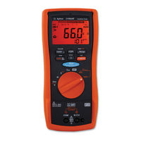
Keysight U1452AT User Manual (122 pages)
Insulation Tester
Brand:
Keysight
| Category:
Test Equipment
| Size: 4 MB
Table of Contents
Table of Contents
13
1 Introduction
21
About this Manual
22
Documentation Map
22
Safety Notes
22
Preparing Your Tester
23
Check the Shipment
23
Install or Change the Batteries
23
Turn on Your Tester
26
Select the Range
26
Adjust the Tilt Stand
27
Connect to the Handheld Meter Logger Software
28
Figure 1-1 Keysight Handheld Meter Logger Software
28
Connect the Bluetooth Adapter
29
Figure 1-2 Bluetooth Adapter Connection
29
Your Tester in Brief
30
Dimensions
30
Figure 1-3 Width Dimension
30
Figure 1-4 Height and Depth Dimensions
31
Overview
32
Table 1-1 Front Panel Part Descriptions
32
Table 1-2 Rear Panel Parts
33
Rotary Switch
34
Table 1-3 U1452A/U1452AT/U1451A Rotary Switch Functions
34
Keypad
36
Table 1-4 U1452A/U1452AT/U1451A Keypad Functions
36
Display Screen
40
Figure 1-5 Display Screen Allocation Example
40
Table 1-5 General Annunciators
40
Table 1-6 Measurement Units Display
42
Table 1-7 Analog Bar Graph Display
43
Input Terminals
44
Figure 1-6 Connecting the Remote Switch Probe
44
Table 1-8 Terminal Connections for Different Measuring
44
Cleaning Your Tester
45
Additional Features
46
Automatic Power-Off
46
Hazardous Voltage Indication
46
Power-On Options
46
Table 1-9 Power-On Options
46
2 Making Measurements
49
Insulation Resistance Test
50
Table 2-1 Rotary Switch Position for Insulation Resistance
50
Figure 2-1 Insulation Resistance Test Example
51
Using the Remote Switch Probe
52
Locking the Test
53
Figure 2-2 T/Time Operation
54
Timed Insulation Resistance/Earth-Bond Resistance Test
54
Figure 2-3 DAR Operation
55
Measuring the Dielectric Absorption Ratio (DAR)
55
Figure 2-4 PI Operation
56
Measuring the Polarization Index (PI)
56
Viewing the Leakage Current
57
Earth-Bond Resistance Test
58
Table 2-2 Earth-Bond Resistance Test Position
58
Figure 2-5 Earth-Bond Resistance Test Example
59
Measuring AC or DC Voltage
61
Table 2-3 AC and DC Voltage Measurement Positions
61
Figure 2-6 AC or DC Voltage Measurement Example
62
Auto AC or DC Signal Identification
63
Measuring Frequency
64
Figure 2-7 Definition of Frequency
65
Measuring Resistance
66
Table 2-4 Resistance Measurement Position
66
Figure 2-8 Resistance Measurement Example
67
Continuity Test
68
Table 2-5 Continuity Test Position
68
Figure 2-9 Continuity Test Example
69
Measuring Capacitance
70
Table 2-6 Capacitance Measurement Position
70
Figure 2-10 Capacitance Measurement Example
71
3 Tester Features
74
Making Relative Measurements (Null)
74
Freezing the Display (Trighold and Autohold)
75
Performing Limit Comparisons (Limit)
77
Table 3-1 Limit Settling Default Values
77
Recording Measurement Data (Log)
79
Table 3-2 Log Maximum Capacity
79
Performing Interval Logs (AUTO)
80
Performing Manual Logs (HAND)
80
Performing Event Logs (TRIG)
81
Table 3-3 Event Log Trigger Conditions
81
Reviewing Previously Recorded Data (View)
83
4 Setup Options
86
Using the Setup Menu
86
Table 4-1 Setup Menu Key Functions
86
Editing Numerical Values
87
Setup Menu Summary
88
Table 4-2 Setup Menu Item Descriptions
88
Setup Menu Items
91
Changing the Variation Count
91
Enabling Smooth Mode
91
Changing the Beep Frequency
92
Changing the Auto Power-Off (APO) Timer
93
Changing the LCD Backlight Timeout
93
Changing the Continuity Alert
94
Disabling the Power-On Melody
95
Changing the Battery Type
95
Resetting the Tester's Setup Options
96
Changing the Display Count
96
Changing the Cable Length Unit
97
Changing the Cable Length Scale
98
Changing the Alert Indicators
98
Changing the Sample Interval Duration
99
Changing the Recording Option
100
Changing the IR and EBR Test Period
100
Changing the Maximum Inhibit Voltage for IR Tests
101
Disabling the Lock Once Feature
102
Changing the Button Operation on the Remote Switch Probe
102
Changing the Dielectric Absorption Ratio (DAR) for IR Tests
103
5 Characteristics and Specifications
105
Product Characteristics
106
Specification Considerations
108
Measurement Category
108
Electrical Specifications
109
DC Specifications
109
Table 5-1 DC Voltage Specifications with Accuracy of
109
Table 5-2 Resistance Specifications with Accuracy of ± (% of Reading + No. of Least Significant Digit)
110
AC Specifications
111
Table 5-3 AC Voltage Specifications with Accuracy of
111
Capacitance Specifications
112
Table 5-4 Capacitance Specifications with Accuracy of ± (% of Reading + No. of Least Significant Digit) [1][2][3]
112
Frequency Specifications
113
Table 5-5 Frequency Specifications with Accuracy of ± (% of Reading + No. of Least Significant Digit) [1][2]
113
Sensitivity for Voltage Measurements
114
Table 5-6 Sensitivity for Voltage Measurements
114
Table 5-7 Insulation Resistance Specifications with Accuracy of ± (% of Reading + No. of Least Significant Digit)
115
Insulation Resistance Specifications
115
Earth-Bond Resistance Specifications
117
EN61557 Specifications
117
Display Update Rate (Approximate)
119
Advertisement
Keysight U1452AT User Manual (106 pages)
Insulation Tester
Brand:
Keysight
| Category:
Test Equipment
| Size: 7 MB
Table of Contents
Copyright Notice
3
Warranty
3
Safety Information
3
Safety Symbols
4
Safety Considerations
5
Measurement Category
7
Environmental Conditions
8
Regulatory Markings
10
Waste Electrical and Electronic Equipment (WEEE) Directive 2002/96/EC
10
Product Category
11
Sales and Technical Support
11
Table of Contents
12
List of Figures
16
List of Tables
18
Introduction
21
About this Manual
21
Documentation Map
21
Safety Notes
21
Preparing Your Tester
22
Check the Shipment
22
Install or Change the Batteries
22
Turn on Your Tester
25
Select the Range
25
Adjust the Tilt Stand
26
Connect to the Handheld Meter Logger Software
27
Connect the Bluetooth Adapter
28
Your Tester in Brief
29
Dimensions
29
Overview
31
Table 1-1 Front Panel Part Descriptions
31
Table 1-2 Rear Panel Parts
32
Rotary Switch
33
Table 1-3 U1452A/U1452AT/U1451A Rotary Switch Functions
33
Keypad
35
Table 1-4 U1452A/U1452AT/U1451A Keypad Functions
36
Display Screen
39
Display Annunciators
39
Table 1-5 General Annunciators
39
Table 1-6 Measurement Units Display
41
Table 1-7 Analog Bar Graph Display
42
Input Terminals
43
Table 1-8 Terminal Connections for Different Measuring
43
Cleaning Your Tester
44
Additional Features
45
Automatic Power-Off
45
Hazardous Voltage Indication
45
Power-On Options
45
Table 1-9 Power-On Options
45
Making Measurements
48
Insulation Resistance Test
49
Using the Remote Switch Probe
51
Locking the Test
52
Timed Insulation Resistance/Earth-Bond Resistance Test
53
Measuring the Dielectric Absorption Ratio (DAR)
54
Measuring the Polarization Index (PI)
55
Viewing the Leakage Current
56
Earth-Bond Resistance Test
57
Table 2-1 Rotary Switch Position for Insulation Resistance Tests .48 Table 2-2 Earth-Bond Resistance Test Position
57
Measuring AC or DC Voltage
60
Table 2-3 AC and DC Voltage Measurement Positions
60
Auto AC or DC Signal Identification
62
Measuring Frequency
63
Measuring Resistance
65
Table 2-4 Resistance Measurement Position
65
Continuity Test
67
Table 2-5 Continuity Test Position
67
Measuring Capacitance
69
Table 2-6 Capacitance Measurement Position
69
Tester Features
72
Making Relative Measurements (Null)
73
Freezing the Display (Trighold and Autohold)
74
Performing Limit Comparisons (Limit)
76
Table 3-1 Limit Settling Default Values
76
Recording Measurement Data (Log)
78
Table 3-2 Log Maximum Capacity
78
Performing Manual Logs (HAND)
79
Performing Interval Logs (AUTO)
79
Performing Event Logs (TRIG)
80
Table 3-3 Event Log Trigger Conditions
80
Reviewing Previously Recorded Data (View)
82
Setup Options
84
Using the Setup Menu
85
Table 4-1 Setup Menu Key Functions
85
Editing Numerical Values
86
Setup Menu Summary
87
Table 4-2 Setup Menu Item Descriptions
87
Setup Menu Items
90
Changing the Variation Count
90
Enabling Smooth Mode
90
Changing the Beep Frequency
91
Changing the Auto Power-Off (APO) Timer
92
Changing the LCD Backlight Timeout
92
Changing the Continuity Alert
93
Disabling the Power-On Melody
94
Changing the Battery Type
94
Resetting the Tester's Setup Options
95
Changing the Display Count
95
Changing the Cable Length Unit
96
Changing the Cable Length Scale
97
Changing the Alert Indicators
97
Changing the Sample Interval Duration
98
Changing the Recording Option
99
Changing the IR and EBR Test Period
99
Changing the Maximum Inhibit Voltage for IR Tests
100
Disabling the Lock Once Feature
101
Changing the Button Operation on the Remote Switch Probe
101
Changing the Dielectric Absorption Ratio (DAR) for IR Tests
102
Characteristics and Specifications
104
Keysight U1452AT Quick Start Manual (21 pages)
Insulation Tester
Brand:
Keysight
| Category:
Test Equipment
| Size: 2 MB
Table of Contents
Standard Accessories Included in Your Purchase
3
Install or Change the Batteries
4
Turn on the Tester
4
The Tester at a Glance
5
Using the Rotary Switch
6
Using the Keypad
7
Using the Input Terminals
8
Insulation Resistance (IR) Test
9
Earth-Bond Resistance (EBR) Test
13
Voltage Measurements
14
Resistance Measurement
15
Continuity Test
16
Capacitance Measurement
17
Safety Notices
19
Safety Symbols
19
Advertisement
Advertisement
Related Products
Keysight U1452A
Keysight U1451A
Keysight U1731C
Keysight U1732C
Keysight U1733C
Keysight U1610A
Keysight U1620A
Keysight U1610/20A
Keysight Infiniium UXR0704BP
Keysight Infiniium UXR0402B
Keysight Categories
Measuring Instruments
Test Equipment
Multimeter
Portable Generator
Power Supply
More Keysight Manuals
Login
Sign In
OR
Sign in with Facebook
Sign in with Google
Upload manual
Upload from disk
Upload from URL