Table of Contents
Advertisement
Quick Links
Advertisement
Table of Contents

Subscribe to Our Youtube Channel
Related Manuals for Commell LV-67W


Summary of Contents for Commell LV-67W
- Page 1 LV-67W Mini-ITX Mobile Motherboard User’s Manual Edition 1.1 2018/08/27...
- Page 2 LV-67W User’s Manual Copyright Copyright 2018, all rights reserved. This document is copyrighted and all rights are reserved. The information in this document is subject to change without prior notice to make improvements to the products. This document contains proprietary information and protected by copyright. No part of this document may be reproduced, copied, or translated in any form or any means without prior written permission of the manufacturer.
- Page 3 LV-67W User’s Manual Packing List: Please check the package content before you starting using the board. 1 x I/O Shield 1 x LV-67W Mini-ITX Motherboard (OPLATE-CDILAT) / (1270067) (include Cooler Fan) 1 x Power Cable 1 x VGA Cable (OALATX-P3S2 / 1040058)
-
Page 4: Table Of Contents
LV-67W User’s Manual Index Chapter 1 <Introduction>............... 4 1.1 <Product Overview>............4 1.2 <Product Specification> ............5 1.3 <Block Diagram>..............6 Chapter 2 <Hardware setup>............7 2.1 <Connector Location and Reference> ........ 7 2.1.1 <Internal connectors list> ..........8 2.1.2 <External connectors list>.........8 2.2 <Memory Setup>..............9... -
Page 5: Chapter 1
LV-67W User’s Manual Chapter 1 <Introduction> 1.1 <Product Overview> LV-67W is Mini-ITX Motherboard which supports 8th generation Intel® Core™ H-series Processor with Intel® QM370 Chipset, integrated HD Graphics , DDR4 memory, Realtek High Definition Audio, Intel Gigabit LAN, Serial ATA3 Intel Coffee Lake-H Processor with Intel®... -
Page 6: Product Specification
LV-67W User’s Manual 1.2 <Product Specification> System Intel® 8th Gen Intel® Core™ H-series Processor Processor FCBGA1440 package Chipset Intel® QM370 2 x DDR4 DIMM 2666 MHz up to 32GB, Memory Support Non-ECC, unbuffered memory only Watchdog Timer Generates a system reset with internal timer for 1min/s ~ 255min/s... -
Page 7: Block Diagram
LV-67W User’s Manual 1.3 <Block Diagram>... -
Page 8: Chapter 2
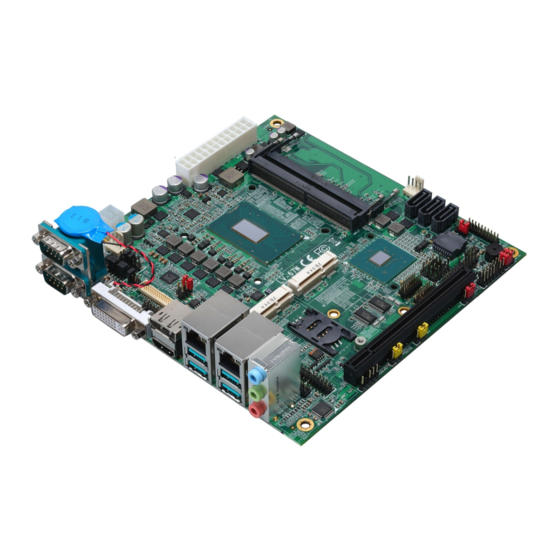
LV-67W User’s Manual Chapter 2 <Hardware setup> 2.1 <Connector Location and Reference> CN_LVDS CN_AUDIO CN_CRT CN_DIO2 CN _INV CN_DIO CPUFAN DC_IN MINI_CARD1 PCI_E16X SIMM MINI_CARD2 CN_COM3/4 CN_COM5/6 DDR4_B CN_USB2-1 CN_LPC CN_PS2 DDR4_A JFRNT SATA3-1 SATA3-2 SATA3-3 CN_USB2-2 SYSFAN AUDIO COM2... -
Page 9: Internal Connectors List
LV-67W User’s Manual 2.1.1 <Internal connectors list> Connector Function DDR4_A/B 288-pin DDR4 DIMM slot SATA3-1/2/3 7-pin Serial ATA3 connector CN_AUDIO 5 x 2-pin audio pin header CN_LPC 6 x 2-pin LPC pin header CN_LVDS 20 x 2-pin LVDS connector CN_INV... -
Page 10: Memory Setup
LV-67W User’s Manual 2.2 <Memory Setup> In the process, the board must be powered off. 1. Put the memory tilt into the slot. Note the Memory notch key aligned slot key. 2. Then press down till lock into the mounting notch. -
Page 11: Jumper Location And Reference
LV-67W User’s Manual 2.3 <Jumper Location and Reference> JVLCD JCSEL2 JCSEL1 CN_SMBUS JMSATA JRTC JFRNT JVUSB JVSATA 2.3.1 <Jumper list> Jumper Function Power mode select JRTC CMOS Normal/Clear Setting JVLCD Panel Voltage Setting JMSATA MiniCard 2 MSATA Setting COM1 Voltage Setting (For Pin 9) -
Page 12: Clear Cmos And Power On Type Selection
LV-67W User’s Manual 2.3.2 <Clear CMOS and Power on type selection> The board’s data of CMOS can be setting in BIOS. If the board refuses to boot due to inappropriate CMOS settings, here is how to proceed to clear (reset) the CMOS to its default values. -
Page 13: Ethernet Interface
LV-67W User’s Manual 2.4.2 <Ethernet interface> The board provide I219-LM PHY Gigabit Ethernet and I210-AT Gigabit Ethernet on rear I/O.Intel I219-LM and I210 supports operation at 10/100/1000 Mb/s data rates, with IEEE802.3 compliance and Wake-On-LAN supported. I219-LM I210-AT 2.4.3 <Display interface>... - Page 14 LV-67W User’s Manual CN_INV CN_CRT CN_LVDS JVLCD CN_CRT: VGA 16-pin connector (Pitch 2.00 mm) Signal Signal IOGND1 IOGND1 IOGND1 IOGND1 IOGND1 5VCDA 5HSYNC 5VSYNC 5VCLK CN_LVDS: LVDS 40-pin connector ( Model: HIROSE DF13-40DP-1.25V compatible Signal Signal Set by JVLCD Set by JVLCD...
- Page 15 LV-67W User’s Manual A_LVDS_1- B_LVDS_1- A_LVDS_1+ B_LVDS_1+ A_LVDS_2- B_LVDS_2- A_LVDS_2+ B_LVDS_2+ A_LVDS_CLK- B_LVDS_3- A_LVDS_CLK+ B_LVDS_3+ A_LVDS_3- B_LVDS_CLK- A_LVDS_3+ B_LVDS_CLK+ LVDS_DDCSCL LVDS_DDCSDA Pin4 only need to be connected to GND CN_INV: LVDS 5-pin Backlight power connector Signal Backlight Control Enable Backlight...
-
Page 16: Serial Port Interface
LV-67W User’s Manual 2.4.4 <Serial Port interface> COM2 COM1 CN_COM3/4 CN_COM5/6 JCSEL1 JCSEL2 JCSEL2 -15-... - Page 17 LV-67W User’s Manual COM1: DB9 connector Signal Signal Set by JP1 COM2: RS232/422/485 DB9 connector Signal Signal DCD/ 422TX-/ 485- RXD/ 422TX+/ 485+ TXD/ 422RX+ DTR/ 422RX- Set by JP2 Note: Use JCSEL1 and JCSEL2 select communication mode COM3/4: COM 20-pin header (Pitch 2.54 x 1.27mm)
- Page 18 LV-67W User’s Manual COM5/6: COM 20-pin header (Pitch 2.54 x 1.27mm) Signal Signal DCD1 RXD1 TXD1 DTR1 DSR1 RTS1 CTS1 DCD2 RXD2 TXD2 DTR2 DSR2 RTS2 CTS2 JP1, JP2: COM1, COM2 pin-9 setting Jumper settings Function RI (Default) Effective patterns of connection: 1-2 / 3-4 / 5-6...
-
Page 19: Usb Interface
LV-67W User’s Manual 2.4.5 <USB interface> USB31 USB3.1 (LEFT) (RIGHT) CN_USB2-1 CN_USB2-2 JVUSB CN_USB3-1 -18-... - Page 20 LV-67W User’s Manual CN_USB 2-1/2-2: USB2.0 10-pin header (Pitch 2.54 mm) Signal Signal 5VSB 5VSB DATA0- DATA1- DATA0+ DATA1+ CN_USB3-1 USB3.1 20-pin header (Pitch 2.00 mm) Description Description (5V_SB/ 5V) USB3.1_RX0- (5V_SB/ 5V) USB3.1_RX0+ USB3.1_RX1- Ground USB3.1_RX1+ USB3.1_TX0- Ground USB3.1_TX0+ USB3.1_TX1-...
-
Page 21: Audio Interface
LV-67W User’s Manual 2.4.6 <Audio interface> Rear Audio Jack Line in Line out Mic in CN_AUDIO CN_AUDIO: Front panel audio 10-pin header (Pitch 2.54mm) Signal Signal MIC_L MIC_R FP_OUT_R MIC_DETECT SENSE FP_OUT_L FP_OUT_DETECT -20-... -
Page 22: Expansion Slot
LV-67W User’s Manual 2.4.7 <Expansion slot> MINI_CARD2 SIMM MINI_CARD1 JMSATA PCI_E16X MINI_CARD1 and MINI_CARD2 have some special design to compatible our mini-PCIe card. (ex: MPX-574D2, MPX-210D2 etc) MINI_CARD2 support mSATA by JMSATA, and connect SIM card with 3G module. JMSATA: Setting MINI_CARD2 to support PCIe/mSATA... -
Page 23: Front Panel Switch And Indicator
LV-67W User’s Manual 2.4.8 <Front panel switch and indicator> JFRNT JFRNT: Front panel switch and indicator 14-pin header (Pitch 2.54mm) Signal Signal HDD_LED+ Power_LED+ HDD_LED- Reset+ Power_LED- Reset- Speaker+ Power_ON+ Power_ON- Speaker- -22-... -
Page 24: Gpio And Other Interface
LV-67W User’s Manual 2.4.9 <GPIO and Other interface> CN_DIO2 CN_DIO1 CPUFAN CN_SMBUS CN_LPC SYSFAN CN_PS2 -23-... - Page 25 LV-67W User’s Manual When using GPIO function Press Delete to enter BIOS Setup menu On Front Page screen, click Setup Utility On Advenced screen, click SIO NCT6116D,then click GPIO 3/4 Configuration Internal Resistance: Select output type, Push pull or Open drain...
- Page 26 LV-67W User’s Manual CN_DIO1: GPIO 12-pin header (Pitch 2.00mm) Signal Signal GP30 GP34 GP31 GP35 GP32 GP36 GP33 GP37 CN_DIO2: GPIO 12-pin header (Pitch 2.00mm) Signal Signal GP40 GP44 GP41 GP45 GP42 GP46 GP43 GP47 CN_LPC: LPC 12-pin header (Pitch 2.00mm)
- Page 27 LV-67W User’s Manual CN_SMBUS: SMBus 5-pin connector (Pitch 2.54mm) Signal SMBDAT SMBCLK CPUFAN: CPU cooler fan 4-pin connector Signal Sensor Control SYSFAN: System cooler fan 4-pin connector Signal Sensor Control -26-...
-
Page 28: Power Supply
LV-67W User’s Manual 2.5 <Power supply> 2.5.1 <Power input> CN_12V DC_IN: 4-pin 9~35V connector Signal Signal 9~35V 9~35V ATX: main power 24-pin connector (DC_IN and ATX can’t use at the same time) Signal Signal 3.3V 3.3V 3.3V -PSON Power_OK 5VSB 3.3V... -
Page 29: Power Output
LV-67W User’s Manual 2.5.2 <Power Output> It is supply to the HDD, CD-ROM or other device. If using DC_IN as input, that ATX will be the output. ATX: main power 24-pin connector (As output) Signal Signal 3.3V 3.3V 3.3V 3.3V... -
Page 30: Appendix A
LV-67W User’s Manual Appendix A <Flash BIOS> A.1 <Flash tool> The board is based on Insyde BIOS and can be updated easily by the BIOS auto flash tool. You can download the tool online at the address below: FPT Tool The tool’s file name is “FPT.exe”, it’s the utility that can write the data into the... -
Page 31: Appendix B
LV-67W User’s Manual Appendix B <LCD Panel Type select> According your panel, it need to select the correct resolution in the BIOS. If there is no fit your panel type, please feedback for us to make OEM modol. Find the setting from Front Page->... - Page 32 LV-67W User’s Manual Advanced SA configurationGraphics confuguration LCD controlLCD Panel Type There are 16 resolutions in LCD Panel Type. (For Dual boot and Legacy boot) -31-...
-
Page 33: Appendix C
LV-67W User’s Manual Appendix C <Programmable Watch Dog Timer> The watchdog timer makes the system auto-reset while it stops to work for a period.The integrated watchdog timer can be setup as system reset mode by program.You can select Timer setting in the BIOS, after setting the time options, the system will reset according to the period of your selection. - Page 34 LV-67W User’s Manual Timeout value range 1 to 255 Minute and Second Program sample Watchdog timer setup as system reset with 5 second of timeout -o 4E 87 ;enter configuration -o 4E 87 -o 4E 07 -o 4F 08 ;select Logical Device...
-
Page 35: Appendix D
LV-67W User’s Manual Appendix D <Hardware Monitor> Find the setting from AdvancedSIO NCT6116DHardware Monitor -34-... -
Page 36: Appendix E
LV-67W User’s Manual Appendix E <Programmable GPIO> The GPIO’ can be programmed with the MS-DOS debug program using simple IN/OUT commands. GPIO -o 4E 87 ;enter configuration -o 4E 87 -o 4E 07 -o 4F 07 ;select Logical Device -o 4E 30 -o 4F 18 ;activate GPIO function (The board use GPIO3,GPIO4) -
Page 37: Appendix F
LV-67W User’s Manual Appendix F <RAID Setting> When use RAID function, it need to enter the BIOS set RAID mode first. Advanced PCH-IO Configuration SATA and RST Configuration SATA Mode Selection At boot time, press <CTRL + I> to enter the RAID configuration menu. -
Page 38: Appendix G
Taiwan Commate computer Inc. 19F., NO.94, Sec. 1, Xintai 5 Rd., Xizhi Dist., New Taipei Address City 22102, Taiwan. +886-2-26963909 +886-2-26963911 Website www.commell.com.tw info@commell.com.tw (General infomation) E-mail tech@commell.com.tw (Technical Support) Commell is a brand name of Taiwan Commate computer Inc. -37-...
Need help?
Do you have a question about the LV-67W and is the answer not in the manual?
Questions and answers