Table of Contents
Advertisement
Quick Links
Pince Multimètre - Courants de fuites
Leakage Clamp-on Meter
Multimeter und Fehlerstrom-Messzange
Pinza Multimetro - Correnti di fuga
Pinza Multímetro - Corrientes de fugas
F 62 – F 65
600
III 100
50 60Hz
MAX
ZERO
FRANÇAIS
Notice de Fonctionnement
ENGLISH
User's manual
DEUTSCH
Bedienungsanleitung
ITALIANO
Libretto d'Istruzioni
ESPANOL
Manual de Instrucciones
1
600
III 100
50 60Hz
MAX
ZERO
F 62
Advertisement
Table of Contents

Subscribe to Our Youtube Channel
Related Manuals for Chauvin Arnoux F 62


Summary of Contents for Chauvin Arnoux F 62
- Page 1 Pince Multimètre - Courants de fuites Leakage Clamp-on Meter Multimeter und Fehlerstrom-Messzange Pinza Multimetro - Correnti di fuga Pinza Multímetro - Corrientes de fugas F 62 – F 65 III 100 III 100 50 60Hz 50 60Hz ZERO ZERO FRANÇAIS...
-
Page 2: Table Of Contents
AC voltage (automatic ranges) ....31 5.2.4. DC voltage (automatic ranges)....31 5.2.5. Resistance (Ω) and continuity ....32 5.2.6. Frequency (automatic ranges)....32 5.2.7. Safety ...........32 5.2.8. General information.........32 5.3. Environment ..........33 5.3.1. Temperature..........33 5.3.2............33 5.4. To order ............. 33 F 62... -
Page 3: General Instructions
CAT IV: CAT IV circuits are circuits in which very large transient over voltages are possible. Example: power feeders For your safety, use only cords complying with the IEC 61010 standard. Before each use, check that they are in perfect working condition. F 62... -
Page 4: While In Use
He/she is authorized to start up and shut down the installation and equipment, in conformity with the safety rules. 1.1.5. Maintenance Clean the instrument with a damp cloth and soap. Do not use abrasive substances or solvents. F 62... -
Page 5: Warranty
If any deterioration is found, state your reservations to the carrier. Attention! For reshipment, it is best to use the original packaging and state the reasons for returning the equipment as clearly as possible in a note enclosed with it. F 62... -
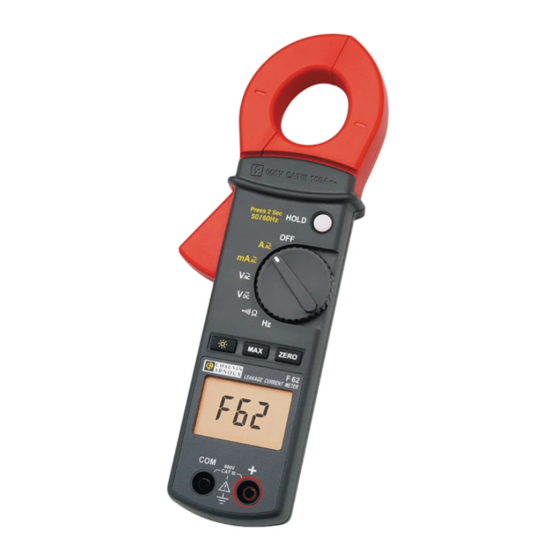
Page 6: Description Of The Instrument
2 Protective guard 3 Trigger 4 MAX function 5 Backlighting function 6 Display unit 7 COM input terminals 8 HOLD function / 50-60Hz filter 9 Switch 10 Display reset (zero) key 11 + Input terminals 12 Battery well F 62... -
Page 7: Description Of The Display Unit
Maximum value display HOLD Hold mode display ZERO Relative Measurement displayed Continuity measurement Voltage measurement Current measurement …Hz Frequency measurement 50-60 Hz Fundamental filter active WIDE Measurement over whole pass band Automatic shut-off activated Alternating current / voltage F 62... -
Page 8: General Description
The acquisition time is 100ms. To deactivate this function, press the "MAX" button again. 3.4. Hold mode (HOLD) The value displayed can be frozen simply by pressing the "HOLD" button. The "HOLD" symbol is then F 62... -
Page 9: Relative Values (Zero)
3.8. Backlighting Pressing the key activates backlighting of the display. The backlighting can be switched off manually by pressing the key; otherwise, it is switched off automatically after 180 seconds. FUNCTIONAL DESCRIPTION 4.1. Alternating current measurement (A range) F 62... - Page 10 The clamp must be placed around a single conductor of a circuit, since otherwise the measurement may be thrown off. The measurement is optimal with the conductor centred in the middle of the jaws. F 62...
-
Page 11: Leakage Current Measurement (Ma Range)
Read the measurement on the display unit. The reading can be filtered to reflect only the fundamental by a long press on the HOLD key, giving an indication of the impact of the harmonics. F 62... -
Page 12: Ac And Dc Voltage Measurements
50 / 60Hz with the points to be measured and read the result on the display unit. PEAK ZERO Note: Before making a measurement on a circuit, 600V check that it is Off and that ANY capacitors are discharged. F 62... -
Page 13: Audible Continuity Test
If the resistance is less than 35 Ω, the buzzer will sound continuously. 600V CAT III 100A 600V CAT III 100A Press 2 Sec HOLD Press 2 Sec 50 / 60Hz HOLD 50 / 60Hz PEAK ZERO PEAK ZERO 600V 600V F 62... -
Page 14: Frequency Measurement (Hz)
Neutral) and release the trigger; check that the clamp is properly closed. Read the measurement result on the display unit. Note: The frequency measurement cannot be made if the clamp-on meter detects both a current measurement and a voltage measurement. F 62... -
Page 15: Specifications
Overload protection: 660 Vrms F 65 : RMS measurement (Rooth Mean Square value) 5.2.4. DC voltage (automatic ranges) Ranges Resolution Accuracy 600V 0.1V 1.0%±2cts Input impedance: 1 MΩ Overload protection: 660 Vrms F 65 : RMS measurement (Rooth Mean Square value) F 62... -
Page 16: Resistance (Ω) And Continuity
4 LCD digits with max. reading of 9,999 points Overload If a reading overshoots the range, the symbol is displayed. Battery Low indicator is displayed when the voltage delivered by the battery is less than the operating voltage. F 62... -
Page 17: Environment
5.3.2. EMC Immunity: as per EN 61326 + A1 (1998) Emissions: as per EN 61326 + A1 (1998) 5.4. To order F 62 P01.12.07.60 F 65 P01.12.07.61 Instrument delivered in a box with: 1 operating manual 1 set of measuring cords (D4mm, one black and one red) 2 1.5V AAA or LR3 batteries...
Need help?
Do you have a question about the F 62 and is the answer not in the manual?
Questions and answers