Table of Contents
Advertisement
Quick Links
Advertisement
Table of Contents

Related Manuals for Chauvin Arnoux F605


Summary of Contents for Chauvin Arnoux F605
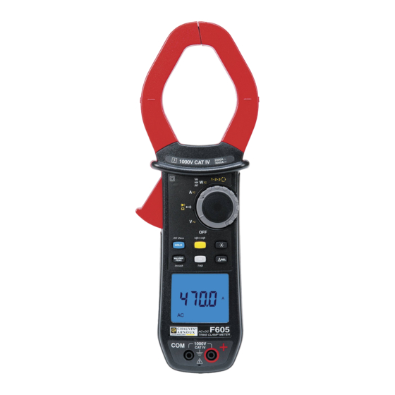
- Page 1 GB - User’s manual F605 Clamp multimeter...
-
Page 2: Table Of Contents
CONTENTS PRESENTATION ......................8 THE SWITCH ........................9 THE KEYS OF THE KEYPAD ..................10 THE DISPLAY UNIT ....................... 11 1.3.1 The symbols of the display unit ..............11 1.3.2 Measurement capacity exceeded (O.L) ............13 THE TERMINALS ......................13 THE KEYS ......................... - Page 3 3.10 STARTING CURRENT OR OVERCURRENT (TRUE INRUSH) MEASUREMENT ............................. 28 3.11 POWER MEASUREMENTS W, VA, AND PF ............. 29 3.11.1 Measurement of single-phase power ............29 3.11.2 Balanced three-phase power measurement ..........30 “DIRECTION OF ROTATION OF THE PHASES” OR “ORDER OF THE PHASES” 3.12 MODE ........................
- Page 4 POWER SUPPLY ......................49 COMPLIANCE WITH INTERNATIONAL STANDARDS ........49 VARIATIONS IN THE DOMAIN OF USE ..............50 MAINTENANCE ....................... 51 CLEANING ........................51 REPLACEMENT OF THE BATTERIES ............... 51 WARRANTY ......................52 DELIVERY CONDITION ..................53...
- Page 5 You have just acquired an F605 clamp multimeter and we thank you. For best results from your device : read this user manual attentively, observe the precautions for its use. Meanings of the symbols used on the device Danger.
- Page 6 PRECAUTIONS FOR USE This device complies with safety standards IEC-61010-1 and 61010-2-032 for voltages of 1000V in category IV at an altitude OF less than 2000m, indoors, with a degree of pollution not exceeding 2. These safety instructions are intended to ensure the safety of persons and proper operation of the device.
- Page 7 As a safety measure, and to avoid repeated overloads on the inputs of the device, we recommend performing configuration operations only when the device is disconnected from all dangerous voltages. MEASUREMENT CATEGORIES Definitions of the measurement categories : CAT II: Circuits directly connected to the low-voltage installation. Example: power supply to household electrical appliances and portable tools.
-
Page 8: Presentation
1 PRESENTATION The F605 is a professional electrical measuring instrument that combines the following functions: Current measurement; Measurement of inrush current / overcurrent (True-Inrush); Voltage measurement; Frequency measurement; Measurement of level of harmonics (THD) Continuity test with buzzer;... -
Page 9: The Switch
THE SWITCH The switch has six positions. To access the , functions, set the switch to the desired function. Each setting is confirmed by an audible signal. The functions are described in the table below. Figure 2 : the switch Item Function See §... -
Page 10: The Keys Of The Keypad
THE KEYS OF THE KEYPAD Here are the six keys of the keypad : Figure 3 : the keys of the keypad Item Function See § Storage of values, disabling of display Zero correction A 3.9.2 AC+DC AC+DC Compensation of the resistance of the leads in the 3.6.1 continuity and ohmmeter function Selection of the type of measurement (AC, DC, AC+DC) -
Page 11: The Display Unit
THE DISPLAY UNIT Here is the display unit of the clamp multimeter: Figure 4 : the display unit Item Function See § Display of the modes selected (keys) Display of the measurement value and unit 3.12 Display of the MAX/MIN/PEAK modes Type of measurement (AC or DC) Total three-phase power measurements 3.11.2... - Page 12 Maximum RMS value Minimum RMS value Peak+ Maximum peak value Peak- Minimum peak value Balanced total three-phase power measurement Volt Hertz Watt Ampere Percentage Ω Milli- prefix Kilo- prefix Reactive power Apparent power Power factor Total harmonic distortion with respect to the fundamental Total harmonic distortion with respect to the true RMS value of the signal.
-
Page 13: Measurement Capacity Exceeded (O.l)
1.3.2 Measurement capacity exceeded (O.L) The O.L (Over Load) symbol is displayed when the display capacity is exceeded. THE TERMINALS The terminals are used as follows: Figure 5 : the terminals Item Function Cold terminal (COM) Hot terminal (+) -
Page 14: The Keys
2 THE KEYS The keys of the keypad respond differently to short, long, and sustained presses. keys provide new functions and allow the detection and acquisition of parameters complementary to the usual elementary measurements. - Each of these keys can be used independently of the others or in perfect complementarity with them: this makes navigation simple and intuitive for looking up all measurement results. -
Page 15: Key (Second Function)
Successive presses on … serve short 1. to store the results of the present measurements 2. to hold the display of the last value displayed 3. to return to normal display mode (the value of each new measurement is displayed) to perform automatic compensation of the zero (see §... -
Page 16: Key
This key is used to backlight the display unit. Successive … serve presses on -to activate or de-activate the backlighting of the screen Remark: the backlighting is switched off automatically at the end of 2 minutes. 2.4.1 In the normal mode This key activates detection of the MAX, MIN, PEAK+ and PEAK- values of the measurements made. -
Page 17: The Max/Min/Peak Mode + Activation Of The Hold Mode
Successive … serve presses on -to activate detection of the MAX/MIN/PEAK values -to display the MAX, MIN, PEAK+ or PEAK- value successively -to return to display of the present measurement without exiting from the mode (the values already detected are not erased) R emark: the MAX, MIN, PEAK+, PEAK- symbols are both displayed, but only the symbol of the quantity selected blinks. -
Page 18: Key
Successive …serves presses on long (>2 sec) to enter the True-INRUSH mode -"Inrh" is displayed for 3s (the backlighting blinks) -the triggering threshold is displayed for 5s (the backlighting is steady); -"------" is displayed and the "A" symbol flashes -after detection and acquisition, the inrush current measurement is displayed, after the calculations stage "------"... -
Page 19: The Hz Function In The Normal Model
2.5.1 The Hz function in the normal model Successive …serves presses on to display: short -the frequency of the signal measured -the present voltage (V) or current (A) measurement to display: -the apparent power (VA) - the reactive power (var) - the power factor (PF) - the frequency of the signal - the active power (W) - Page 20 Successive …serve presses on - to enter the ΔREL mode, to store then display the reference value. The ΔRef symbol is displayed. short - to display the diferential value: - (current value – reference (∆)) The ΔREL symbol is displayed. - to display the relative value in % current value –...
-
Page 21: Use
3 USE COMMISSIONING Insert the batteries supplied with the device as follows: Using a screwdriver, unscrew the screw of the battery compartment cover (item 1) on the back of the housing and open it. Place the 4 batteries in the compartment (item 2), taking care to get the polarities right. -
Page 22: Switching The Clamp Multimeter
SWITCHING THE CLAMP MULTIMETER The clamp multimeter can be switched off either manually, by setting the switch to OFF, or automatically, after ten minutes with no action on the switch and/or the keys. Thirty (30) seconds before the device is switched off, an audible signal sounds intermittently. -
Page 23: Programming Of The Current Threshold For The True Inrush Measurement
3.4.3 Programming of the current threshold for the True INRUSH measurement To program the triggering current threshold of the True INRUSH measurement: 1. in the OFF position, hold the key down while turning the switch to , until the "full screen" display ends and a beep is emitted, to enter the configuration mode. -
Page 24: Voltage Measurement (V)
VOLTAGE MEASUREMENT (V) To measure a voltage, proceed as follows : Set the switch to Connect the black lead to the COM terminal and the red lead to "+". Place the test probes or the crocodile clips on the terminals of the circuit to be measured. -
Page 25: Automatic Compensation Of The Resistance Of The Leads
An audible signal is emitted if there is continuity, and the measured value is displayed on the screen. 3.6.1 Automatic compensation of the resistance of the leads Warning : before the compensation is executed, the MAX/MIN and HOLD modes must be de-activated. To perform automatic compensation of the resistance of the leads, proceed as follows: Short-circuit the leads connected to the device. -
Page 26: Diode Test
The measured value is displayed on the screen Remark : to measure low resistance values, first carry out the compensation of the resistance of the leads (see § 3.6.1). DIODE TEST Warning: Before performing the diode test, make sure that the circuit is cold and any capacitors have been discharged. -
Page 27: Current Measurement (A)
CURRENT MEASUREMENT (A) The jaws are opened by pressing the trigger on the body of the device. The arrow on the jaws of the clamp (see the diagram below) must point in the presumed direction of flow of the current, from the generator to the load. Make sure that the jaws have closed correctly. -
Page 28: Starting Current Or Overcurrent (True Inrush) Measurement
Step 2 : to make a measurement The switch is set to . Select DC or AC+DC by pressing the yellow key until the desired choice is reached. Apply the clamp to only the conductor concerned. The measurement is displayed on screen. 3.10 STARTING CURRENT OR OVERCURRENT (TRUE INRUSH) MEASUREMENT Remark : the measurement can be made only in AC or DC mode (AC+DC mode... -
Page 29: Power Measurements W, Va, Var And Pf
3.11 POWER MEASUREMENTS W, VA, VAR AND PF This measurement is possible en single-phase or in balanced three-phase. Reminder : in DC or AC+DC power measurement, first correct the DC zero in current (see § 3.9.2, step 1) For the power factor (PF) and the powers VA and var, the measurement is possible only in AC or AC+DC. -
Page 30: Balanced Three-Phase Power Measurement
3.11.2 Balanced three-phase power measurement Set the switch to and select VA, var, or PF by pressing the key until the desired choice is reached Press the yellow key until the symbol is displayed. The device automatically displays AC+DC. To select AC, DC, or AC+DC, press the yellow key until the desired choice is reached. -
Page 31: Direction Of Rotation Of The Phases" Or "Order Of The Phases" Mode
3.12 “DIRECTION OF ROTATION OF THE PHASES” OR “ORDER OF THE PHASES” MODE This mode is used to determine the order of the phases of a three-phase network by the "2-wire" method. To determine the order of the phases, proceed as follows: Step 1: determination of a "reference"... -
Page 32: Frequency Measurement (Hz)
3.13 FREQUENCY MEASUREMENT (HZ) The frequency measurement is available in V, W and A for AC and AC+DC quantities. The measurement is based on a count of the passages of the signal through zero (positive-going edges). 3.13.1 Frequency measurement in voltage To measure the frequency in voltage, proceed as follows: Set the switch to and press the... -
Page 33: Measurement Of Frequency In Power
The measured value is displayed on the screen. 3.13.3 Measurement of frequency in power In the single-phase AC or AC+DC Power (W) setting, it is possible to display the frequency of the voltage of the signal on the terminals. In the balanced three-phase AC or AC+DC Power (W) setting, it is possible to display the frequency of the phase-to-phase voltage of the signal on the terminals. -
Page 34: Measurement Of The Thd And Of The Frequency Of The Fundamental In Current
The measurement is displayed on screen. 3.14.2 Measurement of the THD and of the frequency of the fundamental in current Set the switch to and press and hold (>2s) the key. The symbol is displayed. To select THD , press again. -
Page 35: Characteristics
4 CHARACTERISTICS REFERENCE CONDITIONS Quantities of influence Reference conditions Temperature 23°C ±2°C Relative humidity 45% to 75% Supply voltage 6.0V ±0.5V Frequency range of the applied signal 45–65Hz Sine wave pure √2 Peak factor of the applied alternating signal Position of the conductor in the clamp centred Adjacent conductors none... -
Page 36: Ac Voltage Measurement
Note (1) - The display indicates "+OL" above +2000V and "-OL" below – 2000V in REL mode - Above 1000V, a repetitive beep indicates that the voltage being measured is greater than the safety voltage for which the device is guaranteed. -
Page 37: Dc Current Measurement
Note (1) - The display indicates "OL" above 1400V (in PEAK mode). - Above 1000V (DC or RMS), a repetitive beep indicates that the voltage being measured is greater than the safety voltage for which the device is guaranteed. - Bandwidth in AC = 3 kHz Note (2) - Any value between zero and the min. -
Page 38: Ac Current Measurement
4.2.5 AC current measurement Measurement range 0.25 A to 100.0 A to 1000 A to 2000 A 99.99 A 999.9 A Specified 0 to 100% of the measurement range measurement range Uncertainties ± (1% R + 10 pt) ± (1% R +3 pt) ±... -
Page 39: True-Inrush Measurement
Specific characteristics in MAX/MIN mode in current (from 10 Hz to 1 kHz, in AC and AC+DC and from 0.30 A): Uncertainties (zero corrected): add ± (1% R) to the values in the tables above. Capture time of the extrema: approximately 100ms. Specific characteristics in PEAK mode in current (from 10 Hz to 1 kHz in AC and AC+DC): ... -
Page 40: Diode Test
Specific characteristics in MAX/MIN mode: Uncertainties: add 1% R to the values of the table above. Capture time of the extrema: approximately 100ms. 4.2.10 Diode test Measurement range 0.000V to 3.199V DC Specified measurement range 1 to 100% of the measurement range Uncertainties ±... -
Page 41: Active Ac Power Measurements
Note (3) - The measurement result may be perturbed by an instability linked to the current measurement (approximately 0.1A). Example: for a power measurement made at 10A, the instability of the measurement will be 0.1A/10A or 1%. 4.2.12 Active AC power measurements Measurement 5 W to 10.00 kW to... -
Page 42: Active Ac+Dc Power Measurements
Note (7) - In balanced three-phases, with deformed signals (THD and harmonics), uncertainties are guaranted since Ф > 30°. Additionals errors are following , depending of THD : Add +1% for 10% < THD < 20% Add +3% for 20% < THD < 30% Add +5% for 30% <... -
Page 43: Measurement Of Apparent Ac Power
4.2.14 Measurement of apparent AC power Measurement 5 VA to 10.00 kVA to 100.0 kVA to 1000 kVA to range (2) (4) 9999 VA 99.99 kVA 999.9 kVA 2000 kVA (1) Specified 1 to 100% of the measurement measurement 0 to 100% of the measurement range range range Uncertainties... -
Page 44: Measurement Of Reactive Ac Power
Total reactive power ���� = �(���� − ���� 4.2.16 Measurement of reactive AC power where S = apparent power and P = active power 10.00 kvar 100.0 kvar Measurement 5 var to 1000 kvar to range (2) (4) 9999 var 2000 kvar (1) 99,99 kvar 999.9 kvar... -
Page 45: Measurement Of Reactive Ac+Dc Power
Total reactive power ���� = �(���� − ���� 4.2.17 Measurement of reactive AC+DC power where S = apparent power and P = active power 10.00 kvar 100.0 kvar 1000 kvar to Measurement 5 var to 3000 kvar range (2) (4) 9999 var 99.99 kvar 999.9 kvar... -
Page 46: Frequency Measurements
Note 9 - Sign of the power factor according to the four-quadrant rule (§4.2.12): Quadrant 1 : Power factor PF sign + (inductive system) Cos Φ sign + Quadrant 2 : Power factor PF sign - (capacitive system) Cos Φ sign - Quadrant 3 : Power factor PF... -
Page 47: Characteristics In Thdr
4.2.20 Characteristics in THDr Measurement range 0.0 – 100% Specified measurement range 0 to 100% of the measurement range Uncertainties ± (5% R ±2 pts) in voltage ± (5% R ±5 pts) in current Resolution 0.1% 4.2.21 Characteristics in THDf Measurement range 0.0 –... -
Page 48: Environmental Conditions
ENVIRONMENTAL CONDITIONS Environmental conditions in use in storage Temperature -20 C to + 55 C -40 °C to + 70°C ≤90% at 55°C ≤90% up to 70° C Relative humidity (RH) CHARACTERISTICS OF CONSTRUCTION Housing Rigid polycarbonate shell with moulded elastomer covering Polycarbonate Jaws Opening: 60mm... -
Page 49: Power Supply
POWER SUPPLY Batteries 4x1,5V LR6 Mean life >350 hours (without backlighting) Duration of operation before After 10 minutes without action on the switch automatic switching off and/or keys COMPLIANCE WITH INTERNATIONAL STANDARDS Compliant with standards IEC-61010-1, IEC-61010-2- 30, and IEC-61010-2-32: Electric safety 1000V CAT-IV. -
Page 50: Variations In The Domain Of Use
VARIATIONS IN THE DOMAIN OF USE Influence Quantity of Range of Quantity influence influence influenced Typical V AC 0,1%R/10°C V DC 0,1%R/10°C 0,5%R/10°C + 2pts 1%R/10°C* 1,5%R/10°C + 2pts* Temperature -20...+55°C 0,1%R/10°C + 2 pts Ω 0,2%R/10°C + 1°C W AC 0,3%R/10°C + 2 pts 0,15%R/10°C W DC... -
Page 51: Maintenance
5 MAINTENANCE The instrument has no parts that can be replaced by personnel who are not trained and approved. Any non-approved repair or other work, or replacement of a part by an "equivalent", may severely compromise safety. CLEANING Disconnect everything connected to the device and set the switch to OFF. ... -
Page 52: Warranty
6 WARRANTY Except as otherwise stipulated, our warranty is valid for three years starting from the date on which the equipment was sold. Extract from our General Conditions of Sale provided on request. The warranty does not apply in the following cases: ... -
Page 53: Delivery Condition
7 DELIVERY CONDITION The F605 clamp multimeter is delivered in its packaging box with : 2 banana-banana leads, one red and one black 2 test probes, one red and one black 1 black crocodile clip 4 1.5V batteries ...
Need help?
Do you have a question about the F605 and is the answer not in the manual?
Questions and answers