Table of Contents
Advertisement
Quick Links
Advertisement
Table of Contents

Related Manuals for Chauvin Arnoux F405


Summary of Contents for Chauvin Arnoux F405
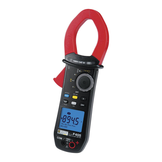
- Page 1 CLAMP MULTIMETER F405 EN G LI S H User’s manual...
-
Page 2: Table Of Contents
CONTENTS PRESENTATION ......................8 THE SWITCH ........................9 THE KEYS OF THE KEYPAD ..................10 THE DISPLAY UNIT ....................... 11 1.3.1 The symbols of the display unit ..............11 1.3.2 Measurement capacity exceeded (O.L) ............12 THE TERMINALS ......................13 THE KEYS ......................... - Page 3 3.11 POWER MEASUREMENTS W, VA, AND PF ............. 27 3.11.1 Measurement of single-phase power ............28 3.11.2 Balanced three-phase power measurement ..........28 “DIRECTION OF ROTATION OF THE PHASES” OR “ORDER OF THE PHASES” 3.12 MODE ..........................29 3.13 FREQUENCY MEASUREMENT (H ) .................
- Page 4 VARIATIONS IN THE DOMAIN OF USE ..............47 MAINTENANCE ....................... 49 CLEANING ........................49 REPLACEMENT OF THE BATTERIES ............... 49 METROLOGICAL CHECK .................... 49 REPAIR ..........................49 WARRANTY ......................50 DELIVERY CONDITION ..................50...
- Page 5 You have just acquired an F405 clamp multimeter and we thank you. For best results from your device : read this user manual attentively, • observe the precautions for its use. • Meanings of the s ymbols us ed on the devic e Danger.
- Page 6 PRECAUTIONS FOR USE This device complies with safety standards IEC-61010-1 and 61010-2-032 for voltages of 1000V in category IV at an altitude OF less than 2000m, indoors, with a degree of pollution not exceeding 2. These safety instructions are intended to ensure the safety of persons and proper operation of the device.
- Page 7 As a safety measure, and to avoid repeated overloads on the inputs of the device, we recommend performing configuration operations only when the device is disconnected from all dangerous voltages. MEASUREMENT CATEGORIES Definitions of the measurement categories : CAT II: Circuits directly connected to the low-voltage installation. Example: power supply to household electrical appliances and portable tools.
-
Page 8: Presentation
PRESENTATION The F405 is a professional electrical measuring instrument that combines the following functions: Current measurement; Measurement of inrush current / overcurrent (True-Inrush); Voltage measurement; Frequency measurement; Measurement of level of harmonics (THD) Continuity test with buzzer;... -
Page 9: The Switch
THE SWITCH The switch has six positions. To access the , functions, set the switch to the desired function. Each setting is confirmed by an audible signal. The functions are described in the table below. Figure 2 : the switch Item Function See §... -
Page 10: The Keys Of The Keypad
THE KEYS OF THE KEYPAD Here are the six keys of the keypad : Figure 3 : the keys of the keypad Item Function See § Storage of values, disabling of display Zero correction A 3.9.2 AC+DC AC+DC Compensation of the resistance of the leads in the 3.6.1 continuity and ohmmeter function Selection of the type of measurement (AC, DC, AC+DC) -
Page 11: The Display Unit
THE DISPLAY UNIT Here is the display unit of the clamp multimeter: Figure 4 : the display unit Item Function See § Display of the modes selected (keys) Display of the measurement value and unit 3.12 Display of the MAX/MIN/PEAK modes Type of measurement (AC or DC) Total three-phase power measurements 3.11.2... -
Page 12: Measurement Capacity Exceeded (O.l)
Maximum RMS value Minimum RMS value Peak+ Maximum peak value Peak- Minimum peak value Balanced total three-phase power measurement Volt Hertz Watt Ampere Percentage Ω Milli- prefix Kilo- prefix Reactive power Apparent power Power factor Total harmonic distortion with respect to the fundamental Total harmonic distortion with respect to the true RMS value of the signal. -
Page 13: The Terminals
THE TERMINALS The terminals are used as follows: Item Function Cold terminal (COM) Hot terminal (+) Figure 5 : the terminals 2 THE KEYS The keys of the keypad respond differently to short, long, and sustained presses. keys provide new functions and allow the detection and acquisition of parameters complementary to the usual elementary measurements. -
Page 14: Key (Second Function)
Remark : the key is invalid for the “Indication of order of phases” function. Successive presses on … serve short 1. to store the results of the present measurements 2. to hold the display of the last value displayed 3. to return to normal display mode (the value of each new measurement is displayed) to perform automatic compensation of the zero Long (>2 sec) -
Page 15: Key
Long (>2 sec) - to display the total three-phase power of a balanced system ( is displayed). - by pressing again, to return to display of the single-phase power ( is off) This key is used to backlight the display unit. Successive …... -
Page 16: The Max/Min/Peak Mode + Activation Of The Hold Mode
Successive presses … serve -to activate detection of the MAX/MIN/PEAK values -to display the MAX, MIN, PEAK+ or PEAK- value successively -to return to display of the present measurement without exiting from the mode (the values already detected are not erased) R emark: the MAX, MIN, PEAK+, PEAK- symbols are both displayed, but only the symbol of the quantity selected blinks. -
Page 17: Key
Successive …serves presses on long (>2 sec) to enter the True-INRUSH mode -"Inrh" is displayed for 3s (the backlighting blinks) -the triggering threshold is displayed for 5s (the backlighting is steady); -"------" is displayed and the "A" symbol flashes -after detection and acquisition, the inrush current measurement is displayed, after the calculations stage "------"... -
Page 18: The Hz Function + Activation Of The Hold Mode
to display: -the apparent power (VA) - the reactive power (var) - the power factor (PF) - the frequency of the signal - the active power (W) - to enter or exit from the level of harmonics long (THD) calculation and display mode - to select THD , THD or the frequency of the... -
Page 19: Use
presses on - to enter the ΔREL mode, to store then display the reference value. The ΔRef symbol is displayed. short - to display the diferential value: - (current value – reference (∆)) The ΔREL symbol is displayed. - to display the relative value in % current value –... -
Page 20: Starting Up The Clamp Multimeter
Figure 6 : the battery compartment cover STARTING UP THE CLAMP MULTIMETER The switch is set to OFF. Turn the switch to the function of your choice. The whole display lights (all symbols) for a few seconds (see §1.3), then the screen of the function chosen is displayed. -
Page 21: Activation Of Automatic Switching Off (Auto Power Off)
From the OFF position, hold the key down while turning the switch to , until the "full screen" display ends and a beep is emitted, to enter the configuration mode. The display unit indicates the value below which the buzzer activated symbol displayed. -
Page 22: Default Configuration
To exit from the programming mode, turn the switch to another setting. The chosen threshold is stored (emission of a double beep). Note: The starting current measurement triggering threshold is fixed at 1% of the least sensitive range. This threshold is not adjustable. 3.4.4 Default configuration To reset the clamp to its default parameters (factory configuration):... -
Page 23: Continuity Test
CONTINUITY TEST Warning : Before performing the test, make sure that the circuit is off and any capacitors have been discharged. Set the switch to ; the symbol is displayed ; Connect the black lead to the COM terminal and the red lead to «+». Place the test probes or the crocodile clips on the terminals of the circuit or component to be tested. -
Page 24: Automatic Compensation Of The Resistance Of The Leads
3.6.1 Automatic compensation of the resistance of the leads Warning : before the compensation is executed, the MAX/MIN and HOLD modes must be de-activated. To perform automatic compensation of the resistance of the leads, proceed as follows: Short-circuit the leads connected to the device. Hold the key down until the display unit indicates the lowest value. -
Page 25: Diode Test
DIODE TEST Warning: Before performing the diode test, make sure that the circuit is cold and any capacitors have been discharged. Set the switch to and press the key twice. The symbol is displayed. Connect the black lead to the COM terminal and the red lead to «+». Place the test probes or the crocodile clips on the terminals of the component to be tested. -
Page 26: Dc Or Ac+Dc Measurement
The measured value is displayed on the screen. 3.9.2 DC or AC+DC measurement To measure the DC or AC+DC current, if the display unit does not indicate "0", first correct the DC zero as follows: Step 1 : to correct the DC zero Important : The clamp must not be closed on the conductor during the DC zero correction. -
Page 27: Power Measurements W, Va, Var And Pf
The measurement is displayed on screen. 3.10 STARTING CURRENT OR OVERCURRENT (TRUE INRUSH) MEASUREMENT Remark : the measurement can be made only in AC or DC mode (AC+DC mode disabled) To measure a starting current or overcurrent, proceed as follows: Set the switch to , correct the DC zero (§... -
Page 28: Measurement Of Single-Phase Power
For the power factor (PF) and the powers VA and var, the measurement is possible only in AC or AC+DC. 3.11.1 Measurement of single-phase power Set the switch to and select VA, var, or PF by pressing the key until the desired choice is reached; The device automatically displays AC+DC. -
Page 29: Direction Of Rotation Of The Phases" Or "Order Of The Phases" Mode
Reminder : the arrow on the jaws of the clamp (see the diagram below) must point in the presumed direction of flow of the current from the source (producer) to the load (consumer) The measurement is displayed on screen. Remark : You can also measure the three-phase power on a balanced 4-wire network by proceeding in the same way, or by proceeding as for the measurement on a single-phase network, then multiplying the value found by three. -
Page 30: Frequency Measurement (Hz)
Step 2: determination of a "measurement" period: Within the next 10 seconds, apply the test probe to the presumed L3 phase. The "MEAS" indication then blinks on the display unit as soon as the L2 phase is disconnected; the device is in the calculation phase. Remark: if the measurement period has not been determined, the device emits a beep and displays the "Err Hz"... -
Page 31: Frequency Measurement In Current
The measured value is displayed on the screen. 3.13.2 Frequency measurement in current Set the switch to and press the key. The Hz symbol is displayed. Select AC or AC+DC by pressing the yellow key until the desired choice is reached. Encircle only the conductor concerned with the clamp. -
Page 32: Measurement Of The Level Of Harmonics (Thd) And Of The Frequency Of The Fundamental (Network)
3.14 MEASUREMENT OF THE LEVEL OF HARMONICS (THD) AND OF THE FREQUENCY OF THE FUNDAMENTAL (NETWORK) The device measures the total harmonic distortion with respect to the fundamental (THD ) and the total harmonic distortion with respect to the true RMS value of the signal (THD ) in voltage and in current. - Page 33 The measurement is displayed on screen.
-
Page 34: Characteristics
4 CHARACTERISTICS REFERENCE CONDITIONS Quantities of influence Reference conditions Temperature: 23°C ±2°C Relative humidity: 45% to 75% Supply voltage: 6.0V ±0.5V Frequency range of the applied signal: 45–65Hz Sine wave: pure Peak factor of the applied alternating signal: √2 Position of the conductor in the clamp: centred Adjacent conductors: none... -
Page 35: Ac Voltage Measurement
Note (1) - The display indicates "+OL" above +2000V and "-OL" below – 2000V in REL mode - Above 1000V, a repetitive beep indicates that the voltage being measured is greater than the safety voltage for which the device is guaranteed. -
Page 36: Ac+Dc Voltage Measurement
4.2.3 AC+DC voltage measurement 0.15 V to 100.0 V to 1000V RMS (1) Measurement range (2) 99.99 V 999.9 V 1400V peak Specified measurement 0 to 100% of the measurement range range Uncertainties from 0.15V to 9.99V ± (1% R+10 pt) ±... -
Page 37: Ac Current Measurement
Note (1) -The display indicates “+OL" above 3000A and "-OL" below –3000A in REL mode. The “-“ and “+” signs are managed (polarity). Note (2) - The residual current at zero depends on the remanence; It can be corrected by the “DC zero” function of the HOLD key. 4.2.5 AC current measurement Measurement range... -
Page 38: True-Inrush Measurement
Specific characteristics in MAX/MIN mode in current (from 10 Hz to 1 kHz in AC and AC+DC, and from 0.30 A): • Uncertainties: add ± (1% R) to the values in the tables above. • Capture time of the extrema: approximately 100ms. Specific characteristics in PEAK mode in current (from 10 Hz to 1 kHz, in AC and AC+DC): •... -
Page 39: Diode Test
Note (1) - Above the maximum display value, the display unit indicates "OL". - The "-" and "+" signs are not managed. Specific characteristics in MAX/MIN mode: • Uncertainties: add 1% R to the values of the table above. • Capture time of the extrema: approximately 100ms. -
Page 40: Active Ac Power Measurements
Example: for a power measurement made at 10A, the instability of the measurement will be 0.1A/10A or 1%. 4.2.12 Active AC power measurements 10.00 kW Measurement 5 W to 100.0 kW to 1000 kW (1) range (2) (4) 9999 W 999.9 kW 99.99 kW Specified... -
Page 41: Active Ac+Dc Power Measurements
Note (7) - In balanced three-phases, with deformed signals (THD and harmonics), uncertainties are guaranted since Ф > 30°. Additionals errors are following , depending of THD : Add +1% for 10% < THD < 20% Add +3% for 20% < THD < 30% Add +5% for 30% <... -
Page 42: Measurement Of Apparent Ac+Dc Power
4.2.15 Measurement of apparent AC+DC power 10.00 kVA 1000 kVA to Measurement 5 VA to 100.0 kVA to 1500 kVA range (2) (4) 9999 VA 999.9 kVA 99.99 kVA Specified 1 to 100% of the measurement 0 to 100% of the measurement range measurement range range Uncertainties... -
Page 43: Measurement Of Reactive Ac+Dc Power
Note 5 - In single-phase, the sign of the reactive power is determined by the phase lead or lag between the U and I signs, while in balanced three- phase, it is determined by the calculation on the samples. Note 6 - Signs of reactive powers according to the four-quadrant rule (§4.2.12): Quadrant 1 : Reactive power Q sign + Quadrant 2 : Reactive power Q... -
Page 44: Calculation Of The Power Factor
4.2.18 Calculation of the power factor Measurement range (1) -1.00 to +1.00 Specified measurement range 0 to 50% of the 50 to 100% of the measurement range measurement range Uncertainties (7) ± (3% R +3 pt) ± (2% R +3 pt) Resolution 0.01 Note (1) - If one of the terms in the calculation of the power factor is displayed as... -
Page 45: Characteristics In Thdr
4.2.19.2 C harac teris tic s in c urrent Measurement range (1) 5.0 Hz to 999,9 Hz 1000 Hz to 1999 Hz Specified measurement 1 to 100% of the 0 to 100% of the range measurement range measurement range Uncertainties ±... -
Page 46: Indication Of Order Of The Phases
4.2.22 Indication of order of the phases Frequency range 47Hz to 400Hz Acceptable voltage range 50V to 1,000V Duration of acquisition of the reference period ≤500ms Duration of validity of the reference period approximately 10s at 50Hz information approximately 2s to 400Hz Duration of acquisition of the measurement period ≤500ms + display of the order of the phases... -
Page 47: Power Supply
POWER SUPPLY Batteries: 4x1,5V LR6 Mean life: >350 hours (without backlighting) Duration of operation before After 10 minutes without action on the switch automatic switching off: and/or keys COMPLIANCE WITH INTERNATIONAL STANDARDS Compliant with standards IEC-61010-1, IEC-61010-2- 30, and IEC-61010-2-32: Electric safety: 1000V CAT-IV. - Page 48 0,2%R 0,3%R + 2 pts Ω 0,25%R 0,5%R + 2 pts 10 Hz...1 kHz 1%R + 1 pt 1%R + 1 pt 1 kHz...3 kHz 9%R + 1 pt 8%R + 1 pt Frequency 10 Hz…400 Hz 1%R + 1 pt 1%R + 1 pt 400 Hz…2 kHz 5%R + 1 pt...
-
Page 49: Maintenance
This instrument should be checked at least once a year. For checks and calibrations, contact one of our accredited metrology laboratories (information and contact details available on request), at our Chauvin Arnoux subsidiary or the branch in your country. REPAIR For all repairs before or after expiry of warranty, please return the device to your distributor. -
Page 50: Warranty
Damage caused by shocks, falls, or floods. • 7 DELIVERY CONDITION The F405 clamp multimeter is delivered in its packaging box with : 2 banana-banana leads, one red and one black • 2 test probes, one red and one black •... - Page 52 Tel: 01 61 61 961-0 - Fax: 01 61 61 961-61 Tel: (01) 89 04 25 - Fax: (01) 89 04 24 SCANDINAVIA - CA Mätsystem AB USA - Chauvin Arnoux Inc - d.b.a AEMC Instruments 200 Foxborough Blvd. - Foxborough - MA 02035 Sjöflygvägen 35 - SE 18304 TÄBY...
Need help?
Do you have a question about the F405 and is the answer not in the manual?
Questions and answers