
Related Manuals for Seastar Solutions i7700


Summary of Contents for Seastar Solutions i7700
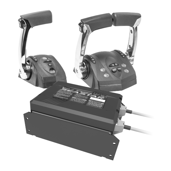
- Page 1 . s e a s t a r s o l u t i o n s . c o m S E V E N T Y S E V E N ISO 9001 i7700 Shift & Throttle System...
- Page 2 Solutions and shall not be disclosed, copied, reproduced or used in whole or in part for any purpose other than as specifically authorized in writing by Marine Canada Acquisition (DBA SEASTAR SOLUTIONS). All information, illustrations and specifications in this manual are based on the latest information available at the time of publishing.
- Page 3 Thank you for choosing an i7700 Electronic Shift and Throttle (EST) System. You have chosen a state of the art shift and throttle system that will provide years of effortless and trouble free performance. About this Book This book contains the information required to install and setup the i7700 EST System.
- Page 4 This page left intentionally blank. © 2017 SeaStar Solutions i7700 Installation Supplement, Rev. B...
-
Page 5: Table Of Contents
6.1 Hazard Definitions ............6-1 6.1.1 Danger ..............6-1 6.1.2 Warning ..............6-1 7.0 Warranty ................7-1 7.1 Statement of Limited Warranty ........... 7-1 7.2 Return Goods Procedure ............ 7-1 7.3 Technical Support .............. 7-1 © 2017 SeaStar Solutions i7700 Installation Supplement, Rev. B... - Page 6 Appendix D – Updating Firmware ............. D-1 D.1 Checking Component Firmware Revision Levels....D-2 D.1.1 Using DATALINK ............D-2 D.2 Updating Actuators and Control Head ........ D-3 D.3 Updating the CANtrak Software......... D-4 © 2017 SeaStar Solutions i7700 Installation Supplement, Rev. B...
-
Page 7: Safety
Every installer and operator of the i7700 system should know the following requirements before installing or operating the system. If you have any questions regarding any of these warnings, contact SeaStar Solutions. - Page 8 DO NOT OPERATE BOAT IF ANY COMPONENT IS NOT IN PROPER WORKING CONDITION. After use The i7700 system requires no special attention after use. Periodically clean the control head with a damp cloth or mild soap. DO NOT use acetone, or cleaners containing ammonia, acids, or any other corrosive ingredients.
-
Page 9: Safety Labels
THE LABELS BELOW SHOULD CALL ATTENTION TO THE POSSIBLE HAZARDS ASSOCIATED WITH THE EQUIPMENT SHOWN LATER IN THIS MANUAL. Component labels The labels shown below are found on the i7700 actuators. Figure 1-1. Actuator decal, PID# 277045. Figure 1-2. Actuator decal sheet, PID# 277044. © 2017 SeaStar Solutions... - Page 10 This page left intentionally blank. © 2017 SeaStar Solutions i7700 Installation Supplement, Rev. B...
-
Page 11: System Overview
The system supports the installation of up to three control heads. The i7700 system consists of the major components listed below. CAN Network CAN (controller area network) is a serial network protocol that is widely used in marine and automotive control systems. -
Page 12: System Overview Diagram
2.2 System Overview Diagram TRIPLE STATION/DUAL ENGINE DUAL STATION/DUAL ENGINE SINGLE STATION/SINGLE ENGINE 1. Control Head 2. Throttle/Shift Actuator Figure 2-1. System Overview. 3. CAN Network Bus © 2017 SeaStar Solutions i7700 Installation Supplement, Rev. B... -
Page 13: Installation
Support Contact To assist with the installation and maintenance of this Electronic Shift and Throttle system SeaStar Solutions recommends that: • Installation MUST be performed by a SeaStar Solutions authorized installer. • Read and understand ALL installation manuals before starting the installation process. - Page 14 TILT/TRIM KIT HA5491 STBD SW PORT SW VIEWED FROM REAR OF SWITCHES STBD ENGINE PORT ENGINE TRIM HARNESS TRIM HARNESS STBD PORT ENGINE ENGINE TRIM TRIM Figure 3-1. Trim switch wiring. © 2017 SeaStar Solutions i7700 Installation Supplement, Rev. B...
-
Page 15: Installing The Actuators
We recommend SeaStar Xtreme cables, P/N CCX633xx. These cables have a minimum bend radius of 8”. NOTICE Do not connect cables to the actuators at this time. © 2017 SeaStar Solutions i7700 Installation Supplement, Rev. B... -
Page 16: Electrical Connections
The preferred source is the engine battery or a battery switch. If you need to extend the leads, follow ABYC codes and practices. SeaStar Solutions recommends a minimum wire size of 10AWG. See the schematic wiring diagram (figure 3-9). Option 1 – single ignition source... -
Page 17: Start-In-Gear Protection
The US Coast Guard requires start-in-gear protection to prevent an engine from starting when forward or reverse gear is engaged. If your engine doesn’t already have this feature, the i7700 actuator can provide start-ingear protection that meets the requirements of 33CFR part 183, subpart L. -
Page 18: Can2 Harness Connections
SECOND STATION MAIN STATION CONTROL HEAD CONTROL HEAD CONTROL HEAD 3' PIGTAIL 3' PIGTAIL 3' PIGTAIL FEMALE TERMINATOR CM10052 CM10060 CM10060 CM10060 Figure 3-4. CAN2 wiring diagram, triple station, twin engine. © 2017 SeaStar Solutions i7700 Installation Supplement, Rev. B... - Page 19 CM10052 * The CE42100 harness contains three flying leads with female bullet connectors. These leads are not used in the i7700 system and should be left unconnected. Figure 3-5. CAN2 wiring diagram, triple station, single engine. © 2017 SeaStar Solutions...
- Page 20 Figure 3-6. Correct CAN2 tee installation example. CAUTION Do not connect anything other than SeaStar components to the CAN2 network. CM20064 SCREWS IN ALL MOUNT HOLES Figure 3-7. Alternative CAN2 6-port hub connection (available separately). © 2017 SeaStar Solutions i7700 Installation Supplement, Rev. B...
-
Page 21: Analog Tachometer
YL – Yellow VT – Violet CAN2 NETWORK YL/RD STARTER SOLENOID ORIGINAL START CIRCUIT ENGINE START ENGINE ANOLOG TACH. – IGNITION KEY SWITCH PANEL POWER SOURCE Figure 3-8. Actuator harness wiring schematic. © 2017 SeaStar Solutions i7700 Installation Supplement, Rev. B... -
Page 22: Nmea Gateway Connection
CAN2 network as shown in figure 3-9. WARNING ALTHOUGH BOTH NETWORKS USE COMPATIBLE CONNECTORS, i6800 CAN2 BUS DO NOT CONNECT THE I7700 NETWORK TO A PUBLIC NMEA 2000 BUS. NMEA 2000 GATEWAY (NOT INCLUDED IN KIT. SEE ENGINE... -
Page 23: System Setup
(P/N EPSK1207). If you prefer to use Datalink you can find instructions in Appendix C. If you are using the tachometer input on the actuator harness (section 3.6) you will need to select i7700 Tach as the RPM Source from the System Setup menu. 4.1 Actuator Setup 4.1.1... - Page 24 8. Move the port and starboard control head levers to the forward and reverse gear positions and verify that the shift actuators move accordingly. Confirm that the control levers are controlling the correct actuators. If not, revisit step 2. © 2017 SeaStar Solutions i7700 Installation Supplement, Rev. B...
- Page 25 12. At this point you need to install the actuator cables. See the i7700 Installation Manual. Figure 4-4. Actuator decal sheet. Figure 4-5. Override decal locations (shaded). © 2017 SeaStar Solutions i7700 Installation Supplement, Rev. B...
-
Page 26: Actuator Adjustment
The 7. Tighten the rod end lock nut (refer to the i7700 installation manual). difference is more pronounced You will need to apply Loctite ®... - Page 27 4. Increase the stroke parameter as necessary to reach the WOT position. Press Save after each adjustment to have it take effect. 5. Tighten the rod end lock nut (refer to the i7700 installation manual). You will need to apply Loctite ®...
-
Page 28: Control Head Setup
4.2 Control Head Setup The i7700 EST system provides a number of control head parameters, listed in table 4-2. User parameters are marked with a (U) but they are For Datalink users: control head parameters are found on not available to the user unless enabled as shown in section 5.7.1. -
Page 29: Sea Trial
On multi-engine boats engage the Power Train Sync feature and check that engine speeds are matched. If the Sync performance is unsatisfactory you may need to add an engine RPM source. See section 3.6. © 2017 SeaStar Solutions i7700 Installation Supplement, Rev. B... -
Page 30: Conclusion Of Sea Trial
• Install the actuator cable covers. Be sure to install them to the correct actuator, because the labels that you applied during installation give manual override instructions specific to the actuator’s type and instance © 2017 SeaStar Solutions i7700 Installation Supplement, Rev. B... -
Page 31: System Faults & Hazards
Indication Dual lever control: the blue Take Command lamp will flash quickly (5 times per second). Single lever control: The amber lamp will flash quickly. © 2017 SeaStar Solutions i7700 Installation Supplement, Rev. B... - Page 32 This page left intentionally blank. © 2017 SeaStar Solutions i7700 Installation Supplement, Rev. B...
-
Page 33: Warranty
In such a case SeaStar Solutions products found to be defective and covered by this warranty, will be replaced at SeaStar Solutions’ option, and returned to the customer. - Page 34 This page left intentionally blank. © 2017 SeaStar Solutions i7700 Installation Supplement, Rev. B...
-
Page 35: Appendix A Mounting Templates
4 x 1/4" 1.5" 1.5" (6.35 mm) DIA. (38 mm) (38 mm) 3" (76 mm) DIA. 1.71" 1.71" (43.5 mm) (43.5 mm) FRONT Figure A-1. Control head – Dual lever mounting template. © 2017 SeaStar Solutions i7700 Installation Supplement, Rev. B... -
Page 36: Control Head - Single Lever
SCALE = 1:1. 3 x 1/4" (6.35 mm) DIA. 3" (76 mm) DIA. 1.6" (41 mm) 1.0" 1.0" (25.4 mm) (25.4 mm) Figure A-2. Control head – Single lever mounting template. © 2017 SeaStar Solutions i7700 Installation Supplement, Rev. B... - Page 37 12.2" (310 mm) 11" (280 mm) CLEARANCE FOR COVER REMOVAL 8x ø0.30" (8 mm) 12" (304 mm) 0.8" (20 mm) 11" (280 mm) Figure A-3. Acuator – Mounting dimensions. NOT A TEMPLATE.. © 2017 SeaStar Solutions i7700 Installation Supplement, Rev. B...
- Page 38 This page left intentionally blank. © 2017 SeaStar Solutions i7700 Installation Supplement, Rev. B...
-
Page 39: Appendix B Using The Color Cantrak Display
DISPLAY The color CANtrak is a powerful tool that can be used to set up the i7700 actuators and perform software updates. Note that the CANtrak is used as a display on other products, so this section will describe functionality that will not be used for i7700 setup. -
Page 40: Documentation Conventions
Steering on the Initial Setup screen. You will frequently need to use the up and down arrows to select menus and parameters, but these actions will not be explicitly described. © 2017 SeaStar Solutions i7700 Installation Supplement, Rev. B... -
Page 41: Initial Startup
All setup and configuration tools are reached from the Dealer Menu, which authorized installers can access with a four digit PIN code (if you don’t have a code contact SeaStar Solutions technical support). From the main run screen, press and hold Menu until you see the PIN entry screen. -
Page 42: Menu Structure
Control broadcast of RPM and gear selection on CAN3 (NMEA 2000) Steering Adjust steering parameters, such as helm effort and number of turns. Shift and Throttle Enable station protection and RPM sync, other settings. I7700 EST only. Yamaha EST Gateway Yamaha DEC engines only. -
Page 43: Appendix C Setup With Datalink
CANtrak display, experienced users may find it quicker to use Datalink for these tasks. C.1 Dealer Tools To use Datalink with an i7700 system you will need the following items, supplied with kit EPSK1206: • IXXAT USB to CAN converter, part #214720 •... - Page 44 TO CAN2 NETWORK TERMINATOR OTHER I6800 COMPONENTS OTHER I6800 COMPONENTS CM21106 CAN2 PROGRAMMING HARNESS CONVERTER 214720 CAN/COMPUTER HARNESS Figure C-1. Dealer Kit connection. © 2017 SeaStar Solutions i7700 Installation Supplement, Rev. B...
-
Page 45: Navigating Datalink
Instead, you open an Interface, which is actually a database that is specially formatted on your screen. The parameter fields (any box with editable values) are cross-referenced to data tables in the devices, but it is not in real-time. © 2017 SeaStar Solutions i7700 Installation Supplement, Rev. B... - Page 46 Likewise, if you are prompted to save changes when you close an Interface, just click No and exit. The save function has nothing to do with whether the changes are saved on your device. © 2017 SeaStar Solutions i7700 Installation Supplement, Rev. B...
-
Page 47: Actuator Setup
C-3 below. Click on the + beside an actuator to view the part and serial number information associated with it. Figure C-3. Shift/Throttle actuator configuration. © 2017 SeaStar Solutions i7700 Installation Supplement, Rev. B... - Page 48 10. Apply manual override direction decals as shown in section 4 (figure 4-9 and figure 4-10). Figure C-4. © 2017 SeaStar Solutions i7700 Installation Supplement, Rev. B...
-
Page 49: Step 2 - Cable Installation And Adjustment
Click Write to save each change. 5. Repeat items 3 and 4 for reverse gear, modifying the Shift to Reverse Throw value as necessary to fully engage the gear. © 2017 SeaStar Solutions i7700 Installation Supplement, Rev. B... - Page 50 Idle Offset parameter (or the actuator adjuster barrels) until they are synchronized. WARNING ® AFTER FINAL ADJUSTMENT IS MADE APPLY LOCTITE 242 (BLUE) AND TIGHTEN JAM NUT ON ACTUATOR SIDE. © 2017 SeaStar Solutions i7700 Installation Supplement, Rev. B...
-
Page 51: Control Head Setup
A forward setting of 50% means that when the throttle lever is fully forward the throttle is limited to 50% of maximum. This provides greater throttle sensitivity when moving at slow speeds. © 2017 SeaStar Solutions i7700 Installation Supplement, Rev. B... - Page 52 Manual for more information. Control Head Instance – If you are setting up a second station, change this parameter to Second. Shift and Throttle Type – Ensure this parameter is set to SeaStar i7700. C-10 © 2017 SeaStar Solutions i7700 Installation Supplement, Rev. B...
-
Page 53: Appendix D Updating Firmware
APPENDIX D UPDATING FIRMWARE This section contains instructions for i7700 Shift and Throttle System, Optimus EPS and Optimus 360 systems. From time to time it may become necessary to update the Datalink notebook software and the i7700 component firmware as new versions become available. -
Page 54: Checking Component Firmware Revision Levels
D.1.1 Using DATALINK 1. Connect the computer to the i7700 system as shown in section C.2. 2. In the ‘Interfaces’ section in Datalink, click on the box to expand the component information. -
Page 55: Updating Actuators And Control Head
D.2 Updating Actuators and Control Head Please contact SeaStar Solutions Technical Support before attempting to update your system firmware. Not all new software releases will be compatible with your system. These instructions are provided for your information only, and assumes that you are updating your firmware under guidance. -
Page 56: Updating The Cantrak Software
10. Key on and power up the i7700 system. 11. Reconnect to the system using Datalink. (It may take a moment for the components to become visible in Datalink) 12. Verify that the latest revision of firmware was loaded to the component as per Section D.1. - Page 57 _______________________________________________ Notes _______________________________________________ _______________________________________________ _______________________________________________ _______________________________________________ _______________________________________________ _______________________________________________ _______________________________________________ _______________________________________________ _______________________________________________ _______________________________________________ _______________________________________________ _______________________________________________ _______________________________________________ _______________________________________________ _______________________________________________ _______________________________________________ _______________________________________________ _______________________________________________ _______________________________________________ © 2017 SeaStar Solutions i7700 Installation Supplement, Rev. B...
- Page 58 _______________________________________________ Notes _______________________________________________ _______________________________________________ _______________________________________________ _______________________________________________ _______________________________________________ _______________________________________________ _______________________________________________ _______________________________________________ _______________________________________________ _______________________________________________ _______________________________________________ _______________________________________________ _______________________________________________ _______________________________________________ _______________________________________________ _______________________________________________ _______________________________________________ _______________________________________________ _______________________________________________ © 2017 SeaStar Solutions i7700 Installation Supplement, Rev. B...
- Page 59 _______________________________________________ Notes _______________________________________________ _______________________________________________ _______________________________________________ _______________________________________________ _______________________________________________ _______________________________________________ _______________________________________________ _______________________________________________ _______________________________________________ _______________________________________________ _______________________________________________ _______________________________________________ _______________________________________________ _______________________________________________ _______________________________________________ _______________________________________________ _______________________________________________ _______________________________________________ _______________________________________________...
- Page 60 SEASTAR SOLUTIONS 3831 NO.6 ROAD RICHMOND, B.C. CANADA V6V 1P6 FAX 604-270-7172 www.seastarsolutions.com © 2017 MARINE CANADA ACQUISITION INC. DBA SEASTAR SOLUTIONS PRINTED IN CANADA 02/18 ISO 10592 Please scan FORM NO. 710351 REV. B this QR code and watch our latest Boating Safety video.
Need help?
Do you have a question about the i7700 and is the answer not in the manual?
Questions and answers