
Related Manuals for Seastar Solutions Seastar PROTAP Controller


Summary of Contents for Seastar Solutions Seastar PROTAP Controller
- Page 1 INSTALLATION INSTRUCTIONS AND OWNER’S MANUAL w w w . s e a s t a r s o l u t i o n s . c o m THIRTY FIVE For the ultimate in Engine ISO 9001 position control...
- Page 2 To the Installer and End User (Owner) Thank you for choosing SeaStar ProTap Controller. This Installation and Owner’s Manual contains all the information that you and others will require for the safe installation and use of the ProTap Controller and MUST remain on board the boat.
-
Page 3: Table Of Contents
INDEX 1.0 Introduction ............ii 2.0 Safety Information ..........1 2.1 General............1 2.2 Important Labels ......... 2 3.0 System Overview ..........5 3.1 How The System Works ....... 5 3.2 System Diagrams ........6 4.0 Installation ............. 12 4.1 Wiring ............12 4.2 Installation Overview ......... -
Page 4: Introduction
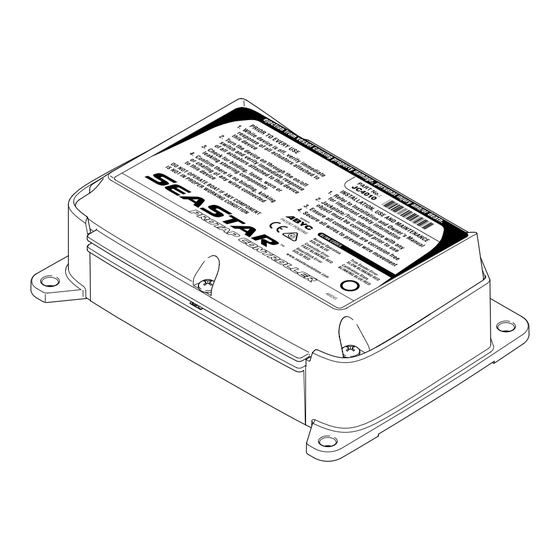
Warranty may be void if products other than SeaStar Solutions products are used with this system. Figure 1-1. SeaStar ProTap Controller... -
Page 5: Safety Information
Installation connect to the controller as directed in appropriate Installation Manuals. 2. DO NOT modify or substitute any component in any way without written consent from SeaStar Solutions. 3. Comply with all system ratings/regulations (boat/ engine, U.S.C.G.). WARNING 4. Confirm that there is no interference between the... -
Page 6: Important Labels
Do not operate boat if any component is not in proper working condition. 2.2 Important Labels The safety information provided below is intended to inform you of the warning information on your product. Please contact SeaStar Solutions if the label is missing. Figure 2-1. SeaStar ProTap Controller... - Page 7 QUICK optimal ride perform- ance, engine RPM and JACKPLATE www.seastarsolutions.com © 2017 Marine Canada Acquisition Inc. PID# 469547A DBA SEASTAR SOLUTIONS 02/17 Printed in Canada Figure 2-3. Bass/Bay Mode Quick User Guide. Installation Instructions and Owner's Manual...
- Page 8 To move Jackplate QUICK in 2” increments. For fi ne Jackplate HOLD motion. www.seastarsolutions.com © 2017 Marine Canada Acquisition Inc. PID# 469548A DBA SEASTAR SOLUTIONS 60–02/17 Printed in Canada Figure 2-4. Flats Mode Quick User Guide. SeaStar ProTap Controller...
-
Page 9: System Overview
3.0 SYSTEM OVERVIEW 3.1 How The System Works Overview ProTap controller is a NMEA 2000 CAN enabled device designed to give you an additional level of control over Jackplate and Trim position. It offers you an ability to quickly get your boat to speed without a need to look at the gauges. -
Page 10: System Diagrams
PROTRIM (OPTIONAL) SWITCH INPUT PROTAP ON/OFF J7: JPSW_DN (GREEN) J6: JPSW_UP (BLUE) J5: PROTAP_SW J9: SS0_POWER J12: SENDER_GND J19: DIGITAL_IO2 (PINK) J13: SENDER_SIG BUZZER (OPTIONAL) +12V +12V 10A FUSE – BATTERY Figure 3-1. Single Jackplate and Gauge. SeaStar ProTap Controller... - Page 11 ENGINE (NOT SUPPLIED BY SEASTAR) NOTE: IF NO GAUGE, CONNECT SMARTSTICK GROUND SS0_GND TO J8 2 WIRES 2 WIRES JACKPLATE HARNESS DW0334 OEM DIGITAL TRIM SENDER ACTUATOR UP RELAY JACKPLATE ACTUATOR DOWN RELAY +12V Referring to figure 4-1 on page 12 match the wiring in the schematic to the pin on the controller.
- Page 12 SWITCH INPUT (OPTIONAL) PROTAP ON/OFF J7: JPSW_DN (GREEN) J6: JPSW_UP (BLUE) J5: PROTAP_SW J9: SS0_POWER J12: SENDER_GND J19: DIGITAL_IO2 (PINK) J13: SENDER_SIG BUZZER (OPTIONAL) +12V +12V 10A FUSE – BATTERY Figure 3-2. Single Jackplate, Gauge and Trim. SeaStar ProTap Controller...
- Page 13 CONTROL HEAD (NOT SUPPLIED BY SEASTAR) OEM POWER OEM POWER TRIM & TILT TRIM & TILT RELAYS MOTOR (NOT SUPPLIED BY SEASTAR) ENGINE (NOT SUPPLIED BY SEASTAR) NOTE: IF NO GAUGE, CONNECT SMARTSTICK GROUND SS0_GND TO J8 2 WIRES 2 WIRES JACKPLATE HARNESS DW0334 JACKPLATE HARNESS DW0334 OEM DIGITAL...
- Page 14 PROTRIM (OPTIONAL) SWITCH INPUT PROTAP ON/OFF J7: JPSW_DN (GREEN) J23: SS1_PWR J6: JPSW_UP J22: SS1_GND (BLUE) J5: PROTAP_SW J9: SS0_POWER J19: DIGITAL_IO2 (PINK) BUZZER (OPTIONAL) +12V +12V 10A FUSE – BATTERY Figure 3-3. Twin Jackplate and Gauge. SeaStar ProTap Controller...
- Page 15 ENGINE (NOT SUPPLIED BY SEASTAR) 2 WIRES JACKPLATE HARNESS DW0334 JACKPLATE HARNESS DW0334 OEM DIGITAL TRIM SENDER ACTUATOR UP RELAY JACKPLATE ACTUATOR DOWN RELAY +12V ENGINE (NOT SUPPLIED BY SEASTAR) NOTE: IF NO GAUGE, CONNECT SMARTSTICK GROUND SS0_GND TO J8 2 WIRES JACKPLATE HARNESS DW0334 JACKPLATE HARNESS DW0334...
-
Page 16: Installation
• Terminals: 9 in-lb (1.02 Nm). the controller are strain relieved. WARNING Ensure all wires are exiting the controller in a down- wards direction. Figure 4-1. Controller Pin-Out. Figure 4-2. Top view of the controller with pin out. SeaStar ProTap Controller... - Page 17 SIGNAL NAME DESCRIPTION BATT+ Power supply input (+) from 12V battery (red). BATT- Power supply input (-) from 12V battery (black or yellow). TRIM_UP Trim Up Output. Connected to engine power trim and tilt up direction (blue). TRIM_DN Trim Down Output. Connected to engine power trim and tilt down direction (green).
- Page 18 ProTap system. WARNING An external buzzer is required if the ProTap controller is mounted in an area where the internal buzzer cannot be heard or is difficult to hear while the boat is underway. SeaStar ProTap Controller...
- Page 19 This page left intentionally blank.
- Page 20 ProTap Wall Mou .25" 6.12 If printing, or ph this page. Using 4.5" that the measu on the print out this page BE 6.62...
- Page 21 unting Template 25" TICE hotocopying from g a ruler, confirm urements shown are as stated on EFORE drilling. 25"...
- Page 22 This page left intentionally blank.
- Page 23 Direct Trim Sender If you are connecting an analog trim sender harness it Connection is important to locate a proper trim sender connector. Trace the wire from the trim sender in the midsection all the way to the connector. Once the trim sender T-harness is connected run the wire to the controller through the engine rigging tube.
- Page 24 To enable trim control the controller needs to be connected to the trim switch wires on the control head. TO CONTROLLER BUTT SPLICE TRIM UP CONTROL TRIM DOWN HEAD BUTT SPLICE TO ENGINE Figure 4-5. Dash Mount Control Head option. SeaStar ProTap Controller...
- Page 25 TO CONTROLLER CONTROL HEAD BUTT SPLICE TRIM UP TRIM DOWN BUTT SPLICE TO ENGINE Figure 4-6. Side Mount Control Head option. Trim Up TWIST WIRES TOGETHER CONTROL HEAD TO ENGINE TRIM UP TRIM UP TO CONTROLLER TRIM UP MOLEX PERMA-SEAL STEP DOWN BUTT SPLICE P/N 0191640043 OR EQUIVALENT Figure 4-7.
- Page 26 The top cover must be properly secured to the ProTap controller while the boat is underway. Failure to do so may result in injury and/or loss of vessel control, leading to possible ejection from vessel causing property damage, personal injury and/or death. SeaStar ProTap Controller...
-
Page 27: Installation Overview
4.2 Installation Overview ProTap controller should be mounted in a cool dry area. Ensure that all wire leads are secured after connecting them to the controller. Use four 1/4 inch corrosion proof screws for mounting. WARNING All electrical connections and harness must comply with ABYC wiring standards, be rated for 105°C (221°F), and compliant with SAE-J1128. - Page 28 This page left intentionally blank. SeaStar ProTap Controller...
-
Page 29: Calibration Procedure
5.0 CALIBRATION PROCEDURE NOTICE Once the controller is properly installed and turned on Refer to section 7 for for the first time, it will need to be calibrated. This will blink and buzzer codes allow the controller to determine the range of Jackplate during calibration. - Page 30 "Smart" mode is operational as per Section 6.0. WARNING If trim signal connected, during initial Tilt Protection check, tilt the engine up slowly and ensure that Tilt Protection is engaged. Failure to do so may result in damage to the vessel or engine components. SeaStar ProTap Controller...
-
Page 31: Operating Modes
6.0 OPERATING MODES ProTap controller is available in two operating modes, B-Mode and F-Mode. These modes are designed for different boating environments. Please see below for a detailed description of each mode and how to utilize the controller. 6.1 Bass/Bay B-Mode (Part # JC4010) This mode is designed to get you quickly up to speed by memorizing the Jackplate and, if connected, trim position. -
Page 32: Flats F-Mode (Part # Jc4020)
It allows you to set the safe position and trim/tilt Dual engine tilt protection threshold. When engine moves to tilt range the only available through Jackplate will move up to a Safe position. a NMEA 2000 harness connection. SeaStar ProTap Controller... -
Page 33: Troubleshooting
If error is reported the controller will switch to Normal mode. Only one error is reported. To clear the error turn the controller off then on. If the error is not cleared please contact SeaStar Solutions Technical Support. Installation Instructions and Owner's Manual... -
Page 34: Warranty
In such a case SeaStar Solutions products found to be defective and covered by this warranty, will be replaced at SeaStar Solutions’ option, and returned to the customer. -
Page 35: Appendix
All SEASTAR SOLUTIONS CAN Bus harness meet the NMEA ® 2000 standard and will work with any other suppliers’... - Page 36 (whichever applies). • Hand-tighten after the connection is made. DO NOT tightly tie down the tee connectors, as this will create stress. SeaStar ProTap Controller...
- Page 37 CAN Bus The Network must consists of a single harness run to which devices are connected by means of a tee Connectivity connector. All products must connect onto the node part of the tee connector. Each end of the harness must have a terminator.
- Page 38 CAN Bus. This requires the CAN Bus to have adequate sources of power. Figure 9-5. SeaStar ProTap Controller...
- Page 39 Notes...
- Page 40 SEASTAR SOLUTIONS 3831 NO.6 ROAD RICHMOND, B.C. CANADA V6V 1P6 FAX 604-270-7172 www.seastarsolutions.com © 2017 MARINE CANADA ACQUISITION INC. DBA SEASTAR SOLUTIONS PRINTED IN CANADA 02/18 ISO 10592 Please scan FORM NO. 469281 REV. F this QR code and watch our latest Boating Safety video.
Need help?
Do you have a question about the Seastar PROTAP Controller and is the answer not in the manual?
Questions and answers